Implementing Multicast using TM and BSMA Algorithm
Pankaj D Khambre
*, Aarti Deshpande
*, Renu Kumari
**, Madhuri Maniktahla
***
GHRCEM, Pune, Maharashtra, India
**
IT Department, BVDUCOE, Pune, India
Abstract- Many applications require to send the information from the source node to the destination node through the communication network. In order to support these applications, it is necessary to determine a path of minimal cost to connect the source node to the destination node. The TM algorithm and BSMA algorithm has been used in order to find the path that minimizes the total cost. The experimental results show that the algorithm can find optimal solution quickly.
I. INTRODUCTION
1.1 DEFINITION
he delivery of information or data to a group of destination computers simultaneously in the single transmission from the source node is known as multicasting.
The most common transport layer protocol to use multicast addressing is User datagram protocol (UDP). UDP is not reliable due to which messages may be lost or delivered out of order reliable multicast protocols such as pragmatic general multicast (PGM) have been developed to add loss detection and retransmission on top of IP multicast.
Amongst the three transmission methods supported by IP, multicasting is the method that is most practical for one-to-many delivery.IP unicasting sends a separate datagram to each recipient host and IP broadcasting sends a single datagram to all hosts on a single network segment (also known as subnet), even to those not interested in receiving it. IP multicast is widely used in enterprises, commercial stock exchanges.
1.2 WORKING
The host and the router should be multicast enabled in order to support multicasting In an internetwork. Routers must support the Internet Group Membership Protocol (IGMP), multicast forwarding, and multicast routing protocols.
The source host sends multicast datagrams to a single Class D IP address, known as the group address. Any host that is interested in receiving the datagrams contacts a local router to join the multicast group and then receives all subsequent datagrams sent to that address.
Multicast routing protocol is used by the router to determine those subnets which includes at least one interested multicast group member and forward multicast datagram only to those subnets that have group members or a router that has downstream group members.TTL (time-to-live) value is included in the IP header of the multicast header to determine how far the routers can forward the multicast datagram.
1.3 ARCHITECTURE
The following figure shows how multicasting components fit in an internetwork.
The major components of multicast architecture are host,router,multicast address, multicast group and MBone. The host that is configured to send the multicast data on multicast-enabled network can send datagrams to a single designated Class D IP address so that multiple hosts can receive the data and the one which is configured to receive the multicast data can use IGMP to join a multicast group and then listen for datagrams sent to the multicast address. Hosts can send and receive multicast data from anywhere on an intranet or the Internet.
The role of multicast router is to manage multicast group membership by processing IGMP requests to join or leave groups and forward multicast traffic to subnets of the internetwork that contain multicast group members.
IP addresses in the Class D range are reserved for IP multicasting. Class D addresses are in the range of 224.0.0.0 to 239.255.255.255.
Multicast group or the host group are the hosts listening for a specific IP Multicast address. Multicast group has no size limit. Multicast groups can be either transient or permanent. Permanent groups are assigned a well-known multicast address.
The MBone is the portion of the Internet that supports the forwarding of Internet-based IP multicast traffic.
T
S
u
b
n
e
t
1
S
u
b
n
e
t
2
S
u
b
n
e
t
3
H
o
s
t
A
H
ISSN 2250-3153
II. RELATED WORK
2.1 ANYCAST
Anycast is a communication technique between a single sender and nearest of several receivers of group. It exists in the contradistinction to multicast, communication between a single sender and multiple receivers, and unicast, communication between a single sender and a single receiver in a network. It is a new networking paradigm supporting service–oriented addresses where an identical address can be assigned to multiple nodes providing a specific service. An anycast packet is delivered to one of these nodes with the same anycast address. Like a multicast address, a single anycast address is assigned to multiple nodes (called anycast membership), but unlike multicasting, only one member of the assigned anycast address communicates with the originator at a time.
Only three connection types are commonly known and used in Internet Protocol version four (IPv4) networks: unicast, multicast and broadcast. A fourth connection type, Anycast, was unknown until IPv6 made it a standard connection type. Anycast is not standardized in IPv4 but can be emulated. IPv4 Anycast addressing is a good solution to provide localization for services and servers so as to achieve robust nature, redundancy and resiliency.
The basic idea of Anycast is very simple: multiple servers, which share the same IP address, host the same service. The routing infrastructure sends IP packets to the nearest server. Better latency times, server load balancing, and improved security are the major benefits of employing Anycast in IPv4. Anycast IPv4 implementations usually involve enabling routing on the server or setting up a static route at the router connected to the server. Tradeoffs are made according to the situation where Anycast is to be used.
Anycast packets can be dropped like any other kind of traffic. Packets are not specifically marked or tagged. Preferably only anyone anycast server receives a packet, but there is no guarantee. It is possible that the sequential packets from a client to anycast address are delivered to different servers. If servers are not synchronized incorrect data maybe sent back. The server that receives a specific packet is solely determined by the unicast routing protocol used in the domain. There is no special anycast routing table equivalent to a separate routing table for multicast traffic. Clients, servers, and routers require no special software/firmware. The only special configuration is needed on servers and routing infrastructure. Therefore, it does not negatively interfere with existing networks or services. Anycast just leverages the existing infrastructure.
2.2 UNICAST
The communication in which the piece of information is sent from one point to another point. There is only one sender and one receiver in this case. In unicast, the packet is sent from a single source to a specified destination. It is predominant form of transmission in LANs and within the internet. All LANs(Ethernet) and IP networks support the unicast transfer mode.
Certain network applications which are mass-distributed are too costly to be conducted with unicast transmission since each
for transmission. Such applications include streaming media of many forms. Internet radio stations using unicast connections may have high bandwidth costs.
There are some standard unicast applications like smtp,ftp,telnet.
2.3 BROADCAST
It is the method which is used to simultaneously send the same message to multiple receivers.
In networking, broadcasting occurs when all the transmitted data packet is received by all the network devices.
A network address is reserved for sending the message to all the machines in the given network segment and that address is known as broadcast address. Ethernet as well as IPv4 use the broadcast address to indicate a broadcast packet. Broadcasting is limited to the LAN (local area network) systems. Internet protocol version 6(IPv6) uses multicasting rather than broadcasting in order to avoid the network interruption when services are requires by any one or two nodes.
Broadcasting is also used to perform a type of DOS (denial of service) attack known as smurf attack. The source IP-address along with the fake ping request is being sent by the attacker. All the replies are then faced by the victim computer and is ultimately flooded. Broadcasting is used in e-mail services and also used by the fax systems.
III. TM ALGORITHM FOR SMALLEST DELAY
It was designed by Takahashi. H and Matsuyama. A .The algorithm finds a Steiner tree by incremental approach called Nearest Destination First (NDF). Initially, the nearest node to the source is found and least cost path between them is selected. Then at each iteration the nearest unconnected destination to the partially constructed tree is found and added into tree. This process is repeated until all destination are included. We use this algorithm to find the minimum delay spanning tree.
BSMA
It is a source based routing algorithm named Bounded Shortest Multicast Algorithm (BSMA). For the construction of delay bounded minimum cost multicast trees.
Network Model & Problem Formulation
In a network model the set of node can be of following types:
1) Source Node: the node connecting to the source that sends out data stream.
2) Destination Node: the node connecting the destination that receives the data stream.
3) Relay Node: the intermediate node in the path between source to destination.
Two position real-valued function are defined on E:
Link Cost Function: (c: E -> R+)
The link delay function deals with the delay and is given by the sum of the perceived queuing delay + transmission delay + propagation delay over the link.
The delay of the path is defined as the sum of link delay along the path.
Destination Delay- bound function or DDF: (δ: D -> R+) DDF assigns an upper bound to the delay along the path from source to destination in D. (i)Can be different from (j) for destination I not equal to j. If DDF assign the same upper bound delay to each destination, the upper bound I denoted by δ(i)= Δ. A Delay bounded Minimum Steiner Tree (DMST) problem is defined as:
DMST Problem: given a graph G=(V,E) with a link-cost function , a link delay function a source S, a set of destination D, and a DDF, then construct a DMST spanning DU{S} such that the cost function of the tree is minimizing while DDF is satisfied.
BSMA Overview
BSMA is a source routing algorithm as it is assumes that the source node has complete information regarding all network link to construct a multicast tree. This can be possible by using any topology broadcast algorithms based on flooding.
It is based on the feasible search optimization method. This method minimizes he objective function constrained inside a feasible region. The feasible region Rb for the BSMA problem
consists of the set of all delay bounded Steiner trees. BSMA starts with an initial tree T0 ε Rb, and iteratively refines the tree
for low cost while staying in the feasible region. BSMA consists of Two major steps
Step 1- construct the initial tree T0 which is a minimum
delay Steiner tree with respect to the multicast source, using TM algorithm given above
Step 2- Iteratively refine T0 for low cost.
Path Switching Algorithm: Input
G (V, E) =graph S=Source Node D= Destination Node
DB= delay bounds(destination node)
Type =cost function type for the tree, which can be utilization driven, to minimize the total link Cost or congestion driven, to minimize the maximal link cost.
Output
A delay bounded Steiner tree spanning D U{S} ProcedureMulticastTree(G (V, E),S , D, DB, Type) {
J 0;
Tj minimum delay tree spanning D U{S} found
using TM algorithm; Loop{
if (Type== utilization driven)
Ph an unmarked superedge in Tj with the highest cost
among all unmarked superedges(not compared with marked superedges);
Else if(Type==congestion driven)
ph an unmarked superedge in Tj with the highest cost
among all superedges(also compared with marked superedges);
if(ph== Null)
return;
Mark superedge ph;
Remove ph from tree Tj getting two T1 and T2 ;
PsDelayBoundedShortestPath(G(V, E),S ,DB ,T1 ,T2 );
J J+1;
Tjps U T1 U T2;
If (ps ≠ ph)
Unmark all marked superedges; }
}
Evaluation of BSMA
The proposers of BSMA proved it always construct a delay bounded multicast tree, if such a tree exits and monotonically decrease the cost of delay bounded tree.
Considering a network of n nodes and denote by k the average number of the k-shortest paths constructed to obtain the delay bounded shortest path. It is shown that the expected time complexity of BSMA is O(kn3log(n)), and O(kn3) in a degree bounded network where the maximal degree is upper bounded.
3.1 PROBLEM STATEMENT
ISSN 2250-3153
Figure 1
[image:4.612.334.552.55.337.2]TM algorithm is applied. In this we assume that total delay should be less than 3.The path followed is AB,AEC,AD. Figure 2 is the solution and the total delay in this case is 2.
Figure 2
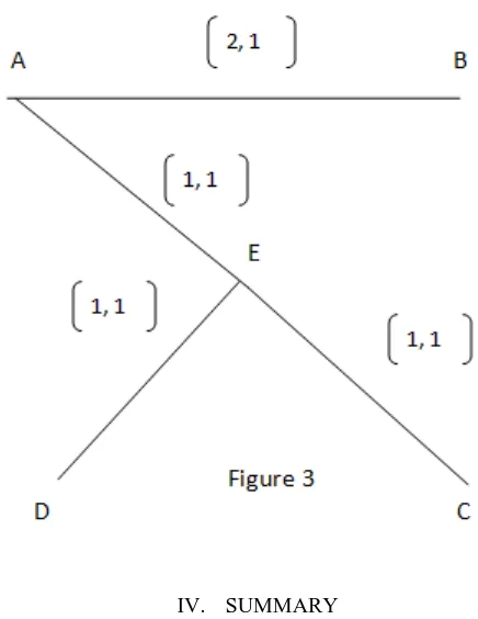
In order to lower the cost, BSMA algorithm is applied. The total cost required in the previous figure is 6.But in order to reduce the cost, the path is changed. The path will be as follows:-AB, AEC, AED. The total cost in this case is 5.Figure 3 is the solution.
IV. SUMMARY
The T M algorithm reduces the original problem to a spanning tree problem by constructing a logical complete graph among the source node and the destination and destination nodes. The computation is easy and fast in most multicast source routing algorithm and policy routing can be easily integrated.
BSMA is a algorithm that is used to optimize and find the minimum of maximum cost of the multicast routing. it is a source based routing algorithm with low complexity.
REFERENCES
[1] Chen, S. & Nahrsted, K., “An Overview of Quality of Service Routing for Next Generation High-speed Networks: Problems and Solutions”, IEEE Network, November/December 1998.
[2] Shacham, N. “ Multicast Communication by Hierarchically Encoded Data”, IEEE INFOCOM’92, May, 1992, pp. 2107-114.
[3] Wang, B. & Hou, J.C., “Multicast routing and its QoS extension: problems, algorithms, and protocols”, IEEE Network Volume: 14 1 , Jan.-Feb. 2000 , Page(s): 22 –36.
[4] Moy, J., “Multicast Extensions to OSPF”, Internet Draft, September, 1992. [5] Deering, S. & Cheriton, D., “ Multicast Routing in Datagram Internetworks
and Extended LANs”, ACM Trans, Comp. Sys. May, 1990, PP. 85-111.
AUTHORS
First Author – Pankaj D Khambre, GHRCEM, Pune, Maharashtra, India, Email: [email protected] Second Author – Aarti Deshpande, GHRCEM, Pune, Maharashtra, India, Email: [email protected]
Third Author – Renu Kumari, IT Department, BVDUCOE, Pune, India, Email: [email protected]
[image:4.612.52.271.431.630.2]