DEVELOPMENT OF A REMOTE CONTROLLED
VERTICALLY ADJUSTABLE WHITE BOARD
Michael Ephraim*,Adimula G. Muyiwa*, Eneida M. Abdulgafar**, Ojo Olatunde Z.**, S.C. Ibeh***
*
Department of Research and Development, Scientific Equipment Development Institute, Minna, Nigeria.
**
Department of Manufacturing Services, Scientific Equipment Development Institute, Minna, Nigeria.
***
Department of Technical Services, Scientific Equipment Development Institute Minna, Nigeria.
Abstract- This paper presents the design and implementation of a remote controlled vertically adjustable motorized white board for the purpose of teaching. The objective is to have a white marker board that can be adjusted to various height so as to aid maximum use of the board by different teachers of varying heights and to have maximum exposure of what is written on the board to a class with same level seat arrangement. Pro-engineering was used for the CAD drawing of the board and Proteus was used to simulate the circuit designed. Furthermore, this design employs the use of a solid white board, motorized jack, rollers and remote control to aid the vertical adjustment of the height of the Whiteboard. The wood used were seasoned and then cut into the various sizes, component by component. These components were assembled and integrated with the electric jack. Using Kiel vision (software for programming) the code for the remote and the receiver were written and tested. The circuit was then assembled on vero board, using Topwin
programmer, the circuit was programmed. After the fabrication, unlike the mechanical solid white board which involves much human effort to push the board through a grooved frame and manually locking it with a bolt by the side for the comfort of the teacher, the Remote control Whiteboard has overcome the manual method of adjustment and aid maximum view in a classroom with same level seat arrangement.
Index Terms- Teaching, vertically, adjustable, roller, solid white board, motorized jack, Pro-engineering, fabrication, and infrared remote control.
I. INTRODUCTION
whiteboard or dry erase board is a name for a glossy surface, most commonly colored white, where non – permanent markings can be made. Whiteboards operate analogously to chalkboard in that they allow markings to temporarily adhere to the surface of the board [1]. Earlier woods and rocks were used for teaching and learning process. The invention ofblackboards was a
revolutionary change in the history of mankind which led to the development of the society. In early 1990s it was observed that allergies and other health risks are associated with chalk boards due to the particles released by the chalk which prompted the replacement of blackboards with whiteboards [2]. Since then, the white board has been largely adopted into many other sectors of human endeavor besides teaching because of its many advantages over the chalkboard [3], [4].
There are currently two different accounts of the history of the whiteboard: one from the US and one from the UK, both dating to the late 1950s to early 1960s. The first version has the white board invented by Martin Heit, a photographer and Korean War veteran who produced it from film laminate. The second account is that Albert Stallion who invented the whiteboards while working at American steel producer Alliance in the 1960s [5]. From records he produced the white board with enameled steel. The limitation of both was that they either were mounted on the wall or on a stand permanently. Remote control motorized cleaners were innovated to reduce the human efforts required for cleaning. This type of cleaner is operated by motors and is controlled by remote. The cleaner move in horizontal direction and due to the pressure applied by the dusters whiteboard is erased [2].
With all these wonderful research done to improve the Whiteboard, the limitation remains that little or no attention was given to the vertical adjustment of the Whiteboard using motorized mechanisms. This impedes maximum view in a class room of same level seat arrangement. Also, it discourages individuals with extreme heights from teaching. This limitation will be overcome by this paper with the use of a motorize jack and rollers fastened to the side of the solid Whiteboard to aid motorized vertical adjustment using a remote thereby making teaching efficient.
II. METHODOLOGY
The design and construction of the new system was achieved with the use of wooden frames, solid Whiteboard, rollers, motorize jack, jack grip, metal rail remote control and an AC to DC converter.
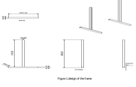
A. Wooden Frames
The motorize board often times needs rigid support so as to stand firm in a class room. This was why stands were made withwooden
frames having dimensions of 65mm by 65mm and a length of 1735mm. These were prepared from wooden beams of 100mm by
100mm and a length of 3300mm. This stands were grooved at the center 18mm wide to a depth of 40mm so as to support the white
board. Also, support beam with a length of 1210mm and thickness of 65mm by 25mm was produced to give rigidity at the top. The
base which will aid the whiteboard to stand was produced with the same dimension as the frames discussed above but with a length of
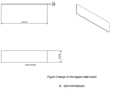
890mm. Support dash board was also produced from plywood of 16mm to give rigidity at the bottom. The dimension of the dashboard
[image:2.612.56.512.220.512.2]is 1244.41mm by 320mm. The CAD drawing showing this component is shown in Figure 1 and 2.
Figure 2.design of the support dash board
B. Solid Whiteboard
[image:3.612.48.489.461.626.2]This was achieved by cutting 12mm plywood 1100mm long and 1180mm wide as shown in Figure 3. Lighter wood may sag when writing on the board. Afterwards, the wood was seasoned so as to ensure that it is absolutely dry. White Formica was then used to laminate the board.
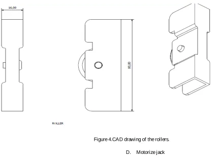
C. Rollers
[image:4.612.47.480.113.431.2]The rollersused asshown in Figure 4 were bought in the local market. This roller was fixed at the side of the solid Whiteboard as shown in Figure 3. This was done to reduce fiction when the board slides through the grove on the frame.
Figure 4.CAD drawing of the rollers.
D. Motorize jack
The motorized jack as shown in Figure 5 was adopted from the mechanism used to position a satellite dish receiver. The jack is made up of a 0.5hp motor, gears and a treaded shaft which ensures good toque. The power specification for the system to work is 36V DC. During the fabrication, 30V DC was used.
[image:4.612.119.387.491.687.2]E. Jack grip
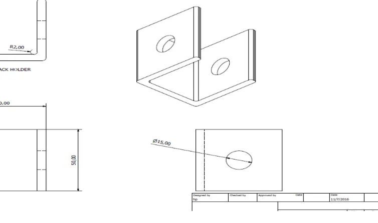
[image:5.612.105.482.143.366.2]The jack grip was made from mild steel plate with thickness of 2mm. The plate was cut to a dimension of 50mm by 50mm so as to form a grip which will couple the Whiteboard with the jack. The plate was formed into U shape as shown in Figure 6 and drilled at the edges with a hole of diameter 12mm which accommodates the bolt which was used to couple the jack to the board.
Figure 6 CAD drawing of the jack grip.
F. Metal rail.
This component was made from a 2mm thick mild steel plate. The plate was cut 18mm wide and 1600mm long. The reason for the selection of the material is to impede the rollers which are metal in structure from eaten up the wood as a result of friction. This rail was then installed into the grove.
G. Remote control.
The remote control is subdivided into two parts. These are the transmitter and the receiver. The block diagram in Figure 7 and Figure 8 shows the interconnectivity of the components of the transmitter and receiver.
Figure 7. Block diagram of infrared transmitter. 9Volts battery
ASTABLE MULTIVIBRATOR
CONTROLLER
NAND GATE IR LED
Max 232
[image:5.612.56.502.562.689.2]Figure 8 Block diagram of receiver.
H. ASTABLE MULTIVIBRATOR
This unit was produced via the use of 555 timer. The timer was connected in astable mode as shown in the circuit diagram in figure 9 below. The essence of this is to generate a 38 kHz square wave which is used as carrier wave. The carrier wave is modulated with the control signal so as to achieve 7 meters range of control. The 0.1nf capacitor is used to stop false trigger. While the combination of R1, R2, and C1 gives the output frequency. This frequency is governed by the formulae
𝑓𝑓=(𝑅𝑅 1.4
2+ 2𝑅𝑅1)𝐶𝐶2
𝑤𝑤ℎ𝑒𝑒𝑒𝑒𝑒𝑒𝑓𝑓=𝑓𝑓𝑒𝑒𝑒𝑒𝑓𝑓𝑓𝑓𝑒𝑒𝑓𝑓𝑓𝑓𝑓𝑓 𝐶𝐶2𝑖𝑖𝑖𝑖𝑖𝑖ℎ𝑒𝑒𝑖𝑖𝑖𝑖𝑒𝑒𝑖𝑖𝑓𝑓𝑒𝑒𝑓𝑓𝑒𝑒𝑒𝑒𝑒𝑒𝑓𝑓𝑖𝑖𝑖𝑖𝑒𝑒𝑒𝑒
𝑅𝑅1𝑒𝑒𝑓𝑓𝑎𝑎𝑅𝑅2𝑒𝑒𝑒𝑒𝑒𝑒𝑖𝑖ℎ𝑒𝑒𝑖𝑖𝑖𝑖𝑒𝑒𝑖𝑖𝑓𝑓𝑒𝑒𝑒𝑒𝑒𝑒𝑖𝑖𝑖𝑖𝑖𝑖𝑖𝑖𝑒𝑒𝑒𝑒𝑖𝑖
Figure 9 Circuit diagram of Astable multivibrator
IR RECEIVER Max 232 CONTROLLER RELAY
AND DRIVER
I. NAND gate and IR LED
[image:7.612.182.425.136.332.2]This was achieved via the use of two NPN transistors. The purpose of having NAND gate is to be able to modulate the carrier wave with the control signal. The circuit diagram is shown in Figure 10 below. R4and R5 are used to properly bias the transistors and R3 is used to limit the current passing through the infrared LED.
Figure 10 circuit diagram of the NAND gate.
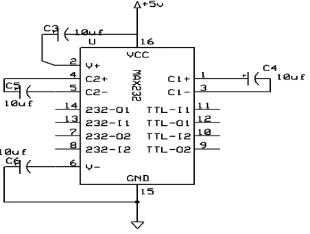
J. MAX 232
The max 232 was used as a serial buffer. In the transmitter, it ensures that the control signal from the controller reaches the NAND gate while in the receiver it ensures that the received signal gets to the controller. The circuit in Figure 11 describes its connection.
Figure 11 circuit diagram of Max232
K. Microcontroller
[image:7.612.185.411.457.628.2]to Vcc so thet the controller can act on the program from within its own program memory. The controller in the transmitter is responsible for the outputting of control signal through the serial transmitter pin (Pin11) while it reads the signal received at the receiver through pin 10. Note that the controller was clocked with a 12MHz crystal.
Figure 12 circuit diagram of the controller.
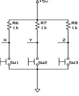
L. Buttons
Three buttons were used. One was dedicated to control the up motion of the jack, another the down motion and the last was the halt action. These buttons were connected in series with a resistor to ensure a difference in logic when pressed. The points X, Y, Z are the points that output the logic. They output logic one when not pressed and logic zero when pressed. The circuit diagram is shown in Figure 13.
Figure 13 circuit diagram of the buttons.
M. IR receiver
[image:8.612.235.369.457.621.2]N. Relay and Driver.
[image:9.612.230.376.149.306.2]The relay is an electromagnetic switch. It help in the changing of the orientation of the jack in this project. To achieve this, two relays were used. These relays had to be controlled by the controller of the receiver. However it was not possible to do that directly since the current demand of the relay is more than what the controller can deliver. To overcome this ill, two A1015 transistors had to be used to drive the relays. This is shown in Figure 13.
Figure 14 circuit diagram of relay and transistor drivers
O. COMPLETE DISCRIPTION OF THE TRANSMITER AND RECIEVER
[image:9.612.109.505.429.718.2]The sub unit shown in Figure 15 consists of an astable multivibrator which generates the 38 kHz needed for modulation. When the button is pressed, the control signal is outputted from the controller to the max 232. This signal in modulated with the 38 kHz carrier signal. This will help to push the message out to the LED. The sub unit in figure 16 shows the IR receiver which captures the message and pass it to Max232. The signal is the passed to the controller which interprets it and acts on it. The assembled board is shown in Figure 17.
Figure 16 Circuit diagram of receiver
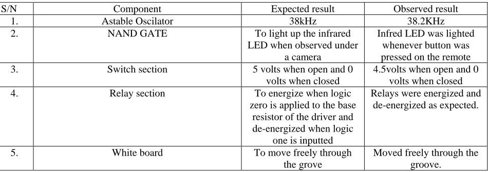
III. TEST AND RESULTS
[image:11.612.35.510.140.308.2]After the completion of the work, unlike the manual Whiteboard that has nothing to measure with a multimeter since there are no circuit involved, essential parameters of some sections of the remote controlled motorize board was measured to ensure that the components were in good condition. This is illustrated with the Table 1 below.
Table 1.Actions of sub units when tested.
S/N Component Expected result Observed result
1. Astable Oscilator 38kHz 38.2KHz
2. NAND GATE To light up the infrared
LED when observed under a camera
Infred LED was lighted whenever button was pressed on the remote
3. Switch section 5 volts when open and 0
volts when closed
4.5volts when open and 0 volts when closed
4. Relay section To energize when logic
zero is applied to the base resistor of the driver and de-energized when logic
one is inputted
Relays were energized and de-energized as expected.
5. White board To move freely through
the grove
Moved freely through the groove.
Furthermore, unlike the manual Whiteboard which needs human effort to adjust the height, the remote controlled whiteboard was operated via the use of a remote. Also the transmitter and receiver were tested to ensure communication.
From the test it was observed that the system worked as anticipated. The remote control worked within the range of 7 meters.
Furthermore, the comfort of teachers with heights between 4.6 feet to height of 6.7 feet was tested. It was observed to be comfortable. Also, in a class of same level seat arrangement, the comfort of the students in viewing the board was achieved.
IV. DISCUSSION OF RESULT
a. The 38.2KHz achieved was because of the tolerance of the timing capacitor and resistors. However, this did not hinder the workability,
b. The NAND gate helped to modulate the control signal as expected. Without it, the distance of control was less than 5cm. c. The switch section helped the controller to know the difference when the switch is closed or open. At logic 1, the switch is
open and at logic 0 the switch is closed. Logic 1 outputs 4.5V instead of the 5V expected. This is due to voltage drop across the pull up resistors.
d. The relays worked as expected, energizing and de-energizing so as to power the electric jack in different directions. e. As a result of the rollers attached to the whiteboard, the movement of the board trough the groove was with less friction. f. Students were quite comfortable since the board could be jacked up to its maximum height. Furthermore, teaches of different
heights attests to how comfortable it is while teaching.
V. CONCLUSION
A remote controlled vertically adjustable motorized white board is designed, constructed and tested. The remote works within the range of 7 meters and it aids conveniences in teaching for teachers of extreme heights. Also, it enhances maximum view in a class of same level seat arrangement.
REFERENCES
[1] Simolowo, O. E. (2014) Preliminary Design of an Automated White Board cleaner. African Research Review, 33, 2070—0083, doi:http://dx.doi.org/10.4314/afrrev.v8i2.5
[2] Bhushan T. C. and Punet M. (2014) Automated Motorized Sensing Whiteboard, International Journal of Advance research in Engineering and Technology, 3, 0976-6480,Retrieved from http://www.iaeme.com/ijaret.asp
AUTHORS
First Author – Michael Ephraim, BEng(Electrical Electronics), Scientific Equipment Development Institute Minna Nigeria, [email protected]
Second Author – Adimula G. Muyiwa, BSc.(Mechanical ), Scientific Equipment Development Institute Minna Nigeria, [email protected]
Third Author –Eneida M. Abdulgafar,HND(Mechanical), Scientific Equipment Development Institute Minna Nigeria, [email protected]
Fourth Author–Ojo Olatunde Z.,BEng.(Metallurgical and Material Engineering),Equipment Development Institute Minna, Nigeria, [email protected]
Fifth Author-- S.C. Ibeh, MEng.(Mechanical), Scientific Equipment Development Institute Minna, Nigeria, [email protected]