Model based Controller Design for Level Process
P.Aravind
Assistant Professor, Department of Instrumentationand Control Engineering, Saranathan College of Engineering ,Trichirappalli,
Tamil Nadu, India
M.Valluvan
Assistant Professor, Department of Electronics andInstrumentation Engineering, JJ College of Engineering and Technology,Trichirappalli Tamil
Nadu, India
B.Sangeetha
Assistant Professor, Department of Electronics andInstrumentation Engineering, JJ College of Engineering and Technology,Trichirappalli Tamil
Nadu, India
ABSTRACT
Control of process parameters are important in the chemical process industries. Proportional, integral and derivative controller is the most commonly used to form a closed loop system for the effective control of process parameter. In this paper, a liquid level in the cylindrical tank is to be controlled at setpoint value. At first, The model for such a real time process is identified and validated. To obtain the effective controller parameters settings, a conventional PID control model based PID were analyzed and the efficiency of the model based PID controller is highlighted with aid of time domain analysis. The ability of the designed model based controller in terms of tracking set point is also compared and simulation results are shown.
General Terms
Control System
Keywords
PID Controller, IMC, Level Process, Z-N
1.
INTRODUCTION
In most of the chemical and plants, level control is extremely important because desired production rates and inventories are achieved through proper control of flow and level. In spite of the enormous attention towards modern control techniques have sparked among researchers during the last few decade, even though in the presence of new control technique industrial persons and researchers are still widely used in many control applications. The reason for their popularity are simplicity, transparency and availability of a larger number of highly efficient, reliable and cost effective commercial PID control modules. To implement a PID controller, three parameters (the proportional gain, Kp; the integral gain, Ki; the derivative gain, Kd) must be determined carefully. Many approaches have been developed to determine PID controller parameter settings for single input single output (SISO) systems. Among the well-known approaches are the Ziegler-Nichols (Z-N) method [1], the Cohen-Coon method [2], Astrom and Hagglund[3] , internal-model-control (IMC) based PID method for first order plus dead time process [4]. Ziegler and Nichols proposed rules for tuning PID controllers based on the transient response characteristics
of a given plant [1].for nonlinear process of a heat exchanger the model, the Internal Model Control (IMC) is applied based on the predictive output of the process model[7]. Model based identification of PID controller parameter settings increases the process consistency and quality. In the process control area, there has been some work along these lines, including the IMC Proportional-Integral (PI)/PID tuning by Rivera et al[8] and Morari and Zafiriou introduced the IMC for process control systems [9].It is based on the predictive output of the process model.
A typical standard for good control is that the response of the system to a step change in set point should have a minimum overshoot, minimum rise time and settling time. To achieve the effective control standards , design of IMC-Based PID control method is proposed in this work to maintain a liquid level in the tank at desired value.
In this work the process dynamics are modeled from a step response analysis by changing the inflow rate of fluid. For the developed model an IMC based PID control structure is designed and its performance measure is based on rise time, settling time and various performance indices are compared with conventional PID controller. In section 2 and 3, we have discussed in detail about the development of the mathematical model for the linear tank process. The tuning method of conventional techniques and the explanation of the IMC based PID and its implementation are discussed in section 4. The comparative studies and results are given in Section 5. The conclusions arrived, based on the results in section 6.
2.
EXPERIMENT SETUP
Fig.1. Piping and Instrument diagram of Experimental Setup
Table.1.Technical details of the experimental setup
PART NAME DETAILS
Tank Transparent body- Cylindrical
Level transmitter Electronic-Range 0–90 cm, Output 4–20mA
Pump Centrifugal 0.5 HP
Control valve Size ¼“ Pneumatic actuated, Type: Air to close, Input 3 – 15 psi
Rotameter Range 10 - 100 LPH
I/P converter Input 4-20 mA, Output 3-15 psi
Pressure gauge Range 0 - 30 psi
3.
STEP TEST METHOD
Step response based methods are most commonly used for system identification. A large number of graphical methods are available in literature and they have been used effectively in real time applications to obtain the model. At first, the inlet valve is at fully opened condition and outlet valve is set to a particular restriction. The open loop step response is obtained by varying the inflow rate, the experimental results are noted in terms of time and height or level. The models are identified
process reaction curve method (PRC)[10] and Sunderasan Kumaraswamy(SK) method [13] method. For a change in step function the PRC method produces a response, from the response parameters like dead time (τd), the time taken for the response to change (τ), and the ultimate value that the response reaches at steady state, τ = 63.2 % of the maximum value are measured and Sunderasan Kumaraswamy(SK) method [13] is used to develop model from the obtained response. As per the structure of the curves, the FOPTD model is given by,
Fin
Fout
Pump
LT
Computer
(Controller)
I/P
Compressor
Control Valve
(1)
Where K is the process gain; τ is the first order time constant; τd is the delay time.
The calculated models are validated with real time results is presented in figure 2 and model obtained through SK method of identification is effectively matches to real time response. From the response of the real time system we obtain the mentioned constants for SK method and thereby we get the FOPTD models for the real time linear tank process as,
(2)
Fig.2. Comparison of real time and simulated responses
4.
CONTROLLER DESIGN
This paper addresses the implementing of PID parameters in two design modes. The basic conventional PID controller technique (ZN) and IMC based PID control technique. With these methods, tuning of PID parameters is performed to achieve a robust design with the desired response time. PID controller is tuned by manually adjusting design criteria in two design modes. The tuner computes PID parameters that robustly stabilize the system.
4.1 Ziegler and Nichols Tuning Method
In this work, the basic design mode is the original Ziegler Nichols [1]scheme, described in Ziegler and Nichols (1943), the critical gain(Ku) and the critical period(Pu) are determined in the following way: a proportional regulator is connected to the system; the gain is gradually increased until an oscillation is obtained; the gain when this occurs is the critical gain and the period of the oscillation is the critical period. It is difficult to automatize this experiment, and perform it in such a way that the amplitude of the oscillation is kept under control. The method is based on the observation that a system with a critical gain Ku at high frequencies may oscillate with period Pu under relay control. To determine the critical gain and the critical period, the system is connected in a feedback loop with a proportional gain constant. It is also desirable to adjust the gain automatically. A reasonable approach is to
require that the oscillation is a given percentage of the admissible swing in the output signal. The PID controller is tuned form oscillatory response parameters. From the response constant parameters of controller Kp,Ki,Kd are calculated using formula.
; ; (4) Where, ;
4.2 IMC based PID
In order to arrive at a PID equivalent form for process with a time delay, we must apporimate the dead time using pade approximation method[11].
τ
τ (5) First order pade approximation for dead time,
(6) PID controller parameters are identified by solving the equation (5and 6 ),
τ τ
τ τ (7) τ τ (8)
ττ
τ τ (9)
5.
RESULTS AND COMPARISON
In this section the tuned values through the ZN method as well as the IMC based PID method are analyzed for their responses point of 25 cm. A tabulation of the time domain specifications comparison and the performance index comparison for the obtained model with the designed controllers is presented. Tuned values based on ZN and IMC based PID control technique are implanted in MATLAB environment and Comparison of two controller are presented in the figure 3. From the response, the IMC based PID controller settings yield a better response the ZN based PID controller settings. A typical criterion effective control is achieved by implementing IMC based PID control technique and the result is analyzed by time domain specification, is tabulated and given in Table2.
Table.2.Obtained Controller Parameters
Controller parameter
ZN IMC-PID
Kp 4.131 3.668
Ki 0.100643 0.017
Kd 42.39 39.95
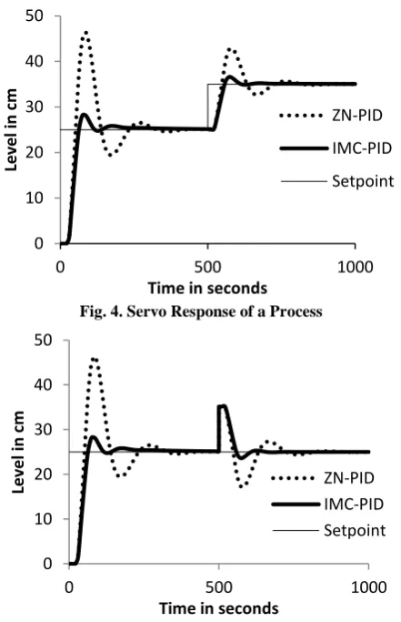
The setpoint is changed from 25 cm and 35 cm, and the response is plotted , shown in figure 4. The load change is given and the response is plotted, is presented in figure 5. IMC based PID controller setting reacts faster to the distrubance than the ZN based PID controller settings. 0
10 20 30 40 50 60 70 80 90
0 200 400 600 800 1000 1200 1400 1600
Level
in
c
m
Time in seconds
RealTime
PRC
Fig.3. Comparison of ZN and IMC for a setpoint of 25 cm
Fig. 4. Servo Response of a Process
Fig.5 . Load Change Response of a Process for PID Controller
[image:4.595.56.277.282.624.2]Fig.6 . Response of a Integral of Absolute Value of Error
Fig.7 . Response of a Integral Square Error (ISE)
The response of IAE and ISE are presented in figure 6 and 7, IMC based PID method which gives a better response for liquid level control process.
Table.3. Comparison of Time Domain Specifications
Specification ZN IMC-PID
Rise time(seconds) 51.9 66.96 Peak time(seconds) 86.58 80
Overshoot(%) 85.26 12.24
Settling time(seconds) 500 450
6.
CONCLUSION
The controller design is the most important concept for a good control, which is achieved if the response has minimum rise and settling time. The obtained results demonstrated that the IMC based PI controller yield good results than ZN method. The performance index under the various error criterions for the proposed controller is always less than the IMC tuned controller and are presented in figure 6 and 7. The various results presented, prove the betterness of the IMC tuned PID settings than the ZN tuned ones. The simulation responses for the models validated reflect the effectiveness of the IMC based PID controller in terms of time domain specifications by achieving minimum rise time, minimum peak time, minimum settling time and overshoot. Hence from the above results it is conclude that IMC seems to be a better choice for the Liquid level control of process tank than conventional PI controllers.
-10 0 10 20 30 40 50
0 500 1000
Level
in
c
m
Time in seconds
ZN-PID
IMC-PID
0 10 20 30 40 50
0 500 1000
Level
in
c
m
Time in seconds
ZN-PID
IMC-PID
Setpoint
0 10 20 30 40 50
0 500 1000
Level
in
c
m
Time in seconds
ZN-PID IMC-PID Setpoint
0 500 1000 1500 2000 2500 3000
0 200 400 600
IA
E
Time in secs
IMC-PID
ZN
0 10000 20000 30000 40000 50000
0 200 400 600
IS
E
Time in seconds
ZN
[image:4.595.323.534.290.441.2]7.
REFERENCES
[1] J. G. Ziegler and N. B. Nichols, “Optimum settings for automatic controllers,” Transactions of American Society of Mechanical Engineers, Vol. 64, 1942, pp. 759-768. [2] G. H. Cohen and G. A. Coon, “Theoretical investigation
of retarded control,” Transactions of American Society of Mechanical Engineers, Vol. 75, 1953, pp. 827-834. [3] Astrom, K J.;. Hagglund .T,1984, Automatic tuning of
simple regulators with specifications on phase and amplitude margins, Automatica, 20,645-651.
[4] B. Wayne Bequette, Process Control: Modeling, Design and Simulation, Prentice Hall (2003) of india.
[5] Asriel U. Levin and Kumpati S. Narendra, Control of nonlinear dynamical systems using Neural Networks- Part II : observability, identification and control, IEEE Transactions on Neural Networks, Vol. 7, No. 1, January 1996.
[6] Simon Fabri and Visakan Kadirkamanathan, Dynamic structure neural networks for stable adaptive control of nonlinear systems, IEEE Transactions on Neural Networks, Vol. 7, No. 5, September1996.
[7] S. Nithya, Abhay Singh Gour, N. Sivakumaran, T. K. Radhakrishnan and N. Anantharaman, Model Based Controller Design for Shell and Tube Heat Exchanger, Sensors and Transducers Journal, Vol. 84, Issue 10, October 2007, pp. 1677-1686.
[8] D. E Rivera, M. Morari, S. Skogestad, Internal model control. PID controller design, J. Ind. Eng. Chem. Res., 25, 1986, pp. 252-265.
[9] M. Morari and E. Zafiriou, Robust process control, Englewood Cliffs, Prentice-Hall, 1989.
[10]D. R. Coughanowar, Process Systems Analysis and Control, Tata McGraw Hill, 1991.
[11]W. B. Bequette, Process Control Modeling and Simulation, Prentice Hall, 2003.
[12]S. Skogestad, Simple analytical rules for model reduction and PID controller tuning, J. Process Control, 13, 2003, pp. 291-309.
[13]Sundaresan, K. R., Krishnaswamy, R. R., Estimation of time delay, time constant parameters in Time, Frequency and Laplace Domains, Journal of Chemical Engineering., 56, 1978, p. 257.
[14]P.Aravind, M.Valluvan,M.Lavanya, Auto Tuning PID Controller for Multi-tank Process, International Journal of Computer Applications (0975 – 8887) Volume 84 – No 4, December 2013