http://dx.doi.org/10.4236/jpee.2014.24054
Simulation Analysis of Control System in
an Innovative Magnetically-Saturated
Controllable Reactor
Xiao Jin
1,2, Guoqiang Zhang
1, Runrui Guo
11Institute of Electrical Engineering, Chinese Academy of Sciences, Beijing, China
2School of Computer and Control Engineering, University of Chinese Academy of Sciences, Beijing, China Email: [email protected]
Received January 2014
Abstract
Controllable saturation reactors are widely used in reactive power compensation. The control system of controllable saturation reactor determines adaption speed, accuracy, and stability. First, an innovative type of controllable saturation reactor is introduced. After that the control system is designed, and a self-tuning algorithm in PID controller is proposed in the paper. The algorithm tunes PID parameters automatically with different error signals caused by varied loads in power system. Then the feasibility of the above algorithm is verified by Simulink module of Matlab soft-ware. The results of simulation indicate that the control system can efficiently reduce adaption time and overshoot.
Keywords
Controllable Saturation Reactor; Parameter Self-Tuning; PID Controller; Reactive Power Compensation
1. Introduction
Reactive compensation apparatus are used in power system to reduce losses in power transmission line, to en-sure stability of voltage, and to adjust power factor [1]. The Magnetic valve type magnetically-saturated con-trollable reactor (MCR) is a main type of reactive compensation apparatus [2]. However, the saturation position of Magnetic valve type MCR is in the main limbs of the iron core, which causes unsatisfactory heat dissipation performance. And Magnetic valve type MCR is three-phase six-limb structure, which costs a number of mate-rials [3]. An innovative controllable reactor, side-limes and side-yokes magnetic-saturation type controllable reactor (SSMCR), was proposed by researchers at Chinese Academy of Sciences, Institute of Electrical Engi-neering. The saturation position of SSMCR is changed to side limbs and side yokes, which efficiently improves heat dissipation performance and reduces material cost [4].
X. Jin et al.
automation. However, when applied in nonlinear, high order and time-delayed linear systems, conventional PID controller may cause long adjusting time, big overshoot, and even system out of control [5]. And what’s more, extremely complicated and fuzzy systems have no precise mathematical models. To solve the problems, various modified conventional PID controllers such as expert control were developed [6], and Non-conventional PID controllers based on fuzzy logic and genetic algorithm have been designed as well [7]-[9]. Due to frequent dras-tic variation of loads and nonlinearity of SSMCR, a self-tuning PID control algorithm is proposed in this paper. Then the simulations are conducted to demonstrate its feasibility and effectiveness.
[image:2.595.200.399.446.542.2]2. Control System Design
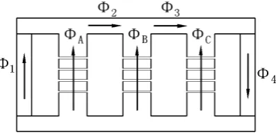
Figure 1 illustrates the outline of SSMCR. Compared with the magnetism valve type MCR, SSMCR changes its saturation position to side-limes and side yokes. DC exciting windings are installed at side-limes. When ΦA, ΦB
and ΦC are sine AC magnetic flux, the Φ1, Φ2, Φ3 and Φ4 are not standard sine wave and contain odd harmonics. Figure 2 is the vector diagram, where Φ1, Φ2, Φ3 and Φ4 are fundamental waves.
If the side-limb windings are excited by DC current, the DC flux will flow through side limbs and yokes. Therefore, magnetic saturation level of side limbs and yokes are changed and its magnetic resistances are changed as well. As a result, the reactance of SSMCR is changed. Its reactance can be calculated as follow:
2
2 0
2π 2π r
M F
c r
fW
X fW S
Rδ R a l
µ
µ
µ
= =
+ + (1)
where W is number of turns of AC winding, Rδ is magnetic resistance of air gap, Rc is magnetic resistance of
side limbs and yokes, SF is cross-section area of side limbs and yokes. α is a constant related with length of air
gap, cross-section area of core. μr is relative permeability which reflects the saturation level of material.
In conclusion, the reactance of SSMCR can be controlled by the DC current in side-limbs winding. μr is
changed with IDC, the equation of μr= f(IDC) cannot be given because of its particular complexity and
nonlinear-ity. The relationship IDC− XM of SSMCR shows in Figure 3. The result is obtained by experiments under U =
380 V.
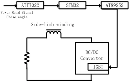
[image:2.595.236.360.571.693.2]Figure 4 shows a typical power grid situation applied SSMCR and Figure 5 is the scheme diagram of control system. ATT7022 is used for as data acquisition equipment (DAE) to collect data of power grid system such as
Figure 1. Construction and magnetic circuit of SSMCR.
Figure 3. Relationship between DC current and reactance.
C SSMCR Control System
R
L1 L2
[image:3.595.191.402.301.432.2]Load
Figure 4. Typical power grid situation applied SSMCR.
DC/DC Convertor
IGBT
ATT7022 STM32 AT89S52
Side-limb winding
Power Grid Signal Phase angle
Figure 5. Scheme diagram of control system.
power factor and phrase angle. STM32 is used as the PID controller which controls the phrase angle (or power factor) of SSMCR to a certain set-point. And the AT89S52 is used as executor to drive the IGBT. In our system, the control system adapts the reactance of SSMCR in terms of phrase angle.
3. Self-Tuning PID Control Algorithm
[image:3.595.190.408.463.600.2]X. Jin et al.
Figure 6. Schematic diagram of PID controller.
(2) (3) where KP, KI and KD are proportional, integral and derivative parameters. KP depends on the present error, KI
depends on the accumulation of past errors, and KDis a prediction of future errors, based on current change rate
[5].
A classification method of error signal |e(t)| (or |e’(t)| when it comes to derivative) is given as Ri:
(4) (5) where 0 ≤ ai< ai+1≤ 1, 0 < i ≤ N, N ∈ Z*. M and M’ is the maximum of expected error.
Based on classification of error signals, parameters tuning principle is designed as: when error signal |e(t)| (or |e’(t)|) rises, proportional should rise, integral should decrease, and derivative should rise. Parameter adaption rules are given (Ri):
(6) (7) (8) where Pnew, Inew and Dnew are the results of parameter tuning. Pold, Iold and Dold are values before parameter tuning.
P0 is the original value of PID controller. ΔP is adaption rate and |ΔP| < 1. ΔP is regarded as the adaption speed
of proportional.
When SSMCR is working, the parameters are changed frequently by the controller based on the proposed al-gorithm. In terms of different classification of error signals, can be found in the rule-table which is given based on SSMCR. Therefore, parameters can be changed in different speeds. Part of rule-table is given in the
Table 1.
4. Simulations
The feasibility and effectiveness of the proposed algorithm are simulated on Matlab. Input is random step signal and outputs are produced by conventional PID controller and self-tuning PID controller. According to output curves (Figure 7), the overshoot produced by conventional PID controller is 7.3% of input variation in average and adaption time is 0.91 s in average. Compared with conventional PID algorithm, the self-tuning PID algo-rithm can efficiently reduce adaption time to 0.13 s and overshoot to zero.
The model of SSMCR is built as follow. The result is produced by curve fitting based on data in Figure 3. (9) where XM is reactance of SSMCR and IDC is exciting DC current.
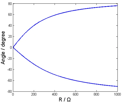
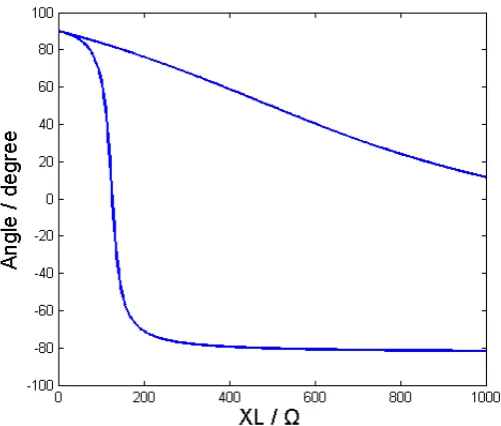
In order to simulate the self-tuning PID algorithm in typical power grid situation in terms of Figure 4, the re-sistance (R) and inductance (L) of load, and capacitance (C) of compensation capacitor should be chosen prop-erly for building the simulation model. When C and L are fixed and R varies, the Figure 8 shows the controlla-ble zone of SSMCR. And Figure 9 is on the situation that R and L are fixed and C varies. Controllable zone is the area between the two curves (maximum curve and minimum curve of system phrase angle).
Figure 7. Outputs of conventional and self-tuning algorithm.
Figure 8. Controllable zone with resistance of loads.
Table 1. Part of rule-table of proportional.
Interval
Proportional
Δ Min Max
[0, 0.25) 0.480 1.00 3.00
[0.25, 0.5) 0.270 1.00 3.00
[image:5.595.150.446.623.713.2]X. Jin et al.
Figure 9. Controllable zone with capacitance of capacitor.
Figure 10. Controllable zone with inductance of loads.
According to Figure 10, when 150 Ω < XL< 800 Ω, the phrase angle of system can be controlled from −43.2˚ to 32.0˚. Therefore, we chosen L = 2.86 H.
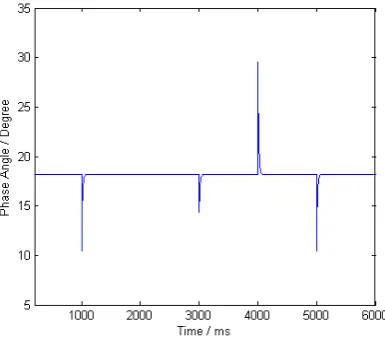
The system model is built in Simulink as shown in Figure 11. In system simulation, input voltage is 380 V and set-point is set to 18.2 (namely cosφ = 0.95). L1 and L2 are switched off and switched on in turns to change
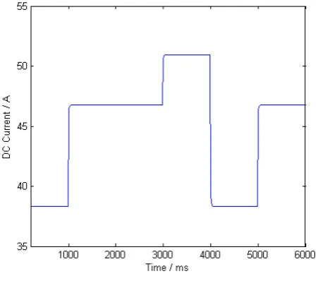
the structure of load. According to Figures 8-10, the controller could control the phase angle of system to set- point. Figure 12 shows the control result of PID controller and Figure 13 shows the IDC curve.
SSMCR with self-tuning PID algorithm can reduce the adaption time to 0.08 s. The overshoots of both phase angle and DC exciting current are zero.
5. Conclusion
[image:6.595.175.426.325.538.2]Figure 11.Simulink schematic diagram of system.
Figure 12. Control result of PID controller.
[image:7.595.202.395.426.596.2]X. Jin et al.
Figure 13. DC exciting current curve.
Since the control system and power grid model are simulated successfully, the experiments will be conducted in next stage based on the simulation data.
References
[1] Wang, H. (2007) Steady-State Analysis of Power Systems (3rd Version). China Electric Power Press, Beijing.
[2] Tian, M.X., Li, Q.F. and Wang, S.H. (2002) An Equivalent Physical Model and a Mathematical Model of the Con- trolled Saturable Rreactor. Transactions of China Electrotechnical Society, 17, 18-21.
[3] Feng, G.H., Wang, F.X. and Jin, W. (2001) Design Principles of Magnetically Controlled Reactor. Electrical Machines and Systems, 2001. Proceedings of the 5th International Conference on IEEE, 1, 212-214.
[4] Zhang, G.Q. and Li, K. (2012) High-Voltage Single Phase Controlled Saturable Rreactor.
[5] Astrom Karl, J. and Hagglund, T. (2006) Advancaed PID Control. ISA.
[6] Shen, Y.F., Wu, S.J. and Deng, F.L. (2002) A Survey of Intelligent PID Control. Industrial Instrumentation & Auto- mation, 6, 11-24.
[7] Man, K.F., Chen, G.R. and Kwong, S. (2001) An Optimal Fuzzy PID Controller. IEEE Transactions on Industrial Electronics, 48, 757-765.
[8] Cao, J.-Y., Liang, J. and Cao, B.-G. (2005) Optimization of Fractional Order PID Controllers Based on Genetic Algo- rithms. Proceedings of 2005 International Conference, Guangzhou, 18-21 August 2005, 9, 5686-5689.