A Resilient Failure Evaluation and Patch-up (R-FEP)
Algorithm for Heterogeneous Distributed Databases
Dharavath Ramesh
Indian School of Mines (ISM) Department of CSE Dhanbad, Jharkhand, India
Chiranjeev Kumar
Indian School of Mines (ISM) Department of CSE Dhanbad, Jharkhand, India
V. Vijay Kumar
SVEC, Suryapet Dept of CSE Andhra Pradesh, India
ABSTRACT
Blocking methodologies sometimes fail to stop malicious things. Attacks on data oriented applications are a serious threat as per the database management systems concern. The required objective of such environment is to find out the mean time attacks and patch up the failures within the stipulated time. This manuscript represents a failure (attacked) evaluation and patch up instances in distributed database systems. The problems like partition, transaction commitment, and failures state that recovery is much more challenging in databases. This manuscript focuses on the challenges and makes an efficient concern with respect to distributed failure evaluation and recovery.
General Terms
Heterogeneity, Distributed Databases, Transaction, Recovery Manager
Keywords
Distributed transaction; intrusion patch up; database security; failure evaluation; recovery.
1.
INTRODUCTION
The role of security is increasing day by day to prevent attacks up to the extent, especially in government and e-business domains. The possibility is not fulfilled to prevent attacks completely. In fact, we must do that not all, even some of the attacks should be ward off at the outset. Several security techniques have been proposed to ward off the attacks in databases such as control [2], [15], authorization mechanisms [3], [4], [16] and distributed secure transaction processing [5]. These are very limited bound to ward off to attacks. And they were not modeled to recognize mean time failures and mean time repairs.
Our approach is on a hard limit of failure tolerant databases, which gives the methodology as failure evaluation and patch up (FEP). The main tendency of the attacks is to disturb the data stored at various databases and mislead the end users to commit wrong decisions. With regard to databases the results of one transaction (T1) instances can be read by other
transaction (T2), i.e. transaction T2 tries to read a data item ‘m’
which is updated by T1, T2 is directly inferred by T1. If a
transaction T3 is inferred by T2, but not directly inferred by
T1, T3 is indirectly inferred by T1. Now consider an instance
when a transaction T0 (old one) updates the data item ‘m’ is
found to be malevolent. This malevolent on the data item ‘m’ can spread to each data item updated by a transaction which is inferred by T0.The responsibility of failure evaluation and
patch up (R-FEP) is to find out the malevolent transaction and recover the database from the failures. Implementation with
respect to this event becomes more difficult because new transactions will perform their operations continuously and this failure case may spread to the new transactions. Therefore, the main theme of malevolent tolerant database is to preserve and failure spreading is controlled dynamically. So, the database will not be disturbed.
The scenario of intrusion tolerant according to the database systems has deeply studied and analyzed by [6], [7], [14], and [8]. But no one has contributed mean time to repair methodology according to distributed transaction. This paper realizes on such methodologies to evaluate and mean time to repair the failure in distributed database transactions. Several algorithms have been developed to evaluate and repair the failure instances in a centralized environment [9], [10]. But in the case of complexity they cannot be used in distributed database environment, novel failure evaluation and recovery methods are needed. Why because partitioning has occurred and data are stored at various sites, failure evaluation and immediate patch up should be performed at various sites. When a distributed transaction accesses a data item which is stored at multiple sites needs to coordinate the relationship with other transactions. Then only failure evaluation and recovery can tolerate site failures as well as communication failures.
1.1
Our Realistic Idea and Methodology
Some recovery techniques were proposed in the case of centralized systems [9], [13], [11], [12] they stated their perception in data-oriented and transaction methods, where data methods use the read and write primitives of transactions to recognize the failures which are spread from one data item to another. A transaction method evaluates and recovers the failures by recognizing the affected transactions. In this paper, we elaborate the centralized scenario to distributed, in particular, we propose an efficient transaction evaluation algorithm to evaluate and patch up the failure one which is occurred in distributed systems. The algorithm is as follows:
It’s totally distributed. Hence, no occurrence of single point failure and also bears malevolent attacks at both end systems and communication links.
New transactions can continuously exchange their data items during the FEP process.
FEP is performed in parallel, at each site.
It supports in all DBMS, so it can be directly applied to construct R-FEP.
2.
DISTRIBUTED DATABASE MODEL
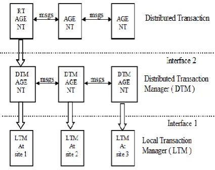
[image:2.595.56.292.310.480.2]A distributed database is a collection of data which belong logically to the same system but are spread over the sites of a computer network. Distributed transactions are an order of read and write primitives on the data items that either commits or aborts [1]. The execution status of the transaction is modeled by a distributed log history. Transactions can have globally unique identifiers which indicate the location of the each site. For the convenience, we treat that each participating site has only one process of that transaction. The coordinator process begins the execution of the distributed transaction; each process is located at the site with the components like transaction manager (TM), scheduler (SC), and recovery manager (RM). A distributed transaction model is depicted in Fig 1. And the transaction recovery mechanism is depicted in Fig. 2 with regard to the local transaction manager (LTM) which is interconnected with distributed transaction manager (DTM). And the DTM takes the responsible consideration to link its messages with the coordinator (stated as Root Agent in Fig. 2) For the distribution.
[image:2.595.60.273.527.695.2]Fig 1: Distributed transaction processing
Fig 2: Distributed transaction recovery mechanism
We consider the particularity of distributed database system supports transaction serializability with concern two- phase locking (2PL) protocol. We also consider the two-phase commit (2PC) protocol instance for the atomicity of transactions, despite site or link failures. The scenario of
conventional 2PC protocol is managed two prepare log records as follows. When a user decides to commit (according to Fig 1) a transaction, the coordinator (RT Agent as in Fig 2) comes in picture and sends PREPARE messages to participants. Each participant wait for PREPARE message. If it is willing to commit then, it writes READY record in the log and sends YES message to the coordinator. If it wants to abort, then it writes ABORT record in the log and sends NO to coordinator. After receiving the messages from the participants at coordinator side, if all messages were YES, then the coordinator writes the commit log record and sends COMMIT message to all the participants. If it has received even one No, again it writes abort log record and sends ABORT message to all the participants. Each participant after receiving a COMMIT/ABORT message, it writes the log record as COMMIT/ABORT and sends an ACK message to the coordinator. When the coordinator receives ACK message from all the participants in the second phase, it writes complete/end record in the log. With regard to this our R-FEP algorithm is specified based on the way how log records are maintained.
2.1
Resilient Failure Evaluation and Patch
up Model
Our basic instinct on R-FEP is that only malevolent transactions and the inferred transactions can cause problems and should be repaired in the mean time. We first define the problematic relationship between the transactions; the failure can be only caused by all committed transactions. Here, we denote the set of committed malevolent transactions by a set M = {M1, M2, M3... Mn} and the set of good conditioned transactions by a set C= {C1, C2, C3….Cm}.
At a site X, a committed transaction Tij is dependent upon Tjk if a data item ‘m’ is stored at that site such that Tij reads ‘m’ after Tjk updates ‘m’, and no other transaction updates ‘m’ between the time. A committed distributed transaction Tj is affected by transaction Ti if the pair (Tj, Ti) is transitively dependent. To know it more precisely, consider a set {M1, C1, C2} which is executed on two sites.
At Site X: Sx:
M1: Read (m): Write (m): Commit;
C1: Read (m): Read (n): Write (n): Commit;
C2: Read (z): Write (z): Commit;
At Site Y: SY:
M1: Read (o): Write (o): Commit;
C1: Read (p): Write (p): Commit;
C2: Read (p): Read (q) Write (q) Commit;
According to SX, we came to know that the transaction C1 is dependent to M1, because it is reading the same data item ‘m’ so C1 is inferred by M1, and the data items ‘m’ and ‘n’ are not realistic (damaged). Again we know that C2 is either dependent to M1 or C1. However, this is not incurred that, C2 will not be affected by M1.
According to SY, we came to know that the transaction C2 is dependent to C1 (although C2 is not dependent to M1). Hence, C2 is dependent to C1, since C1 is dependent to M1, so (C2, M1) is in the form of transitive closure dependent. Therefore, C2 is caused by M1 and the data item ‘q’ is damaged.
3.
THE R-FEP ALGORITHM
3.1
Description of R-FEP
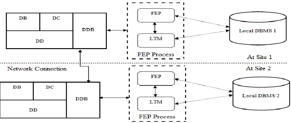
Several commercially distributed systems were developed by the vendors of centralized database management systems. They contain additional components which extend the capabilities of several DBMSs by supporting communication and cooperation between several instances which are installed at different sites of a network. Here we consider two types of processes to perform distributed resilient FEP: a Local Transaction Manager (LTM) on each site and a FEP module at each site. The architecture of our components is shown in Fig. 3.
The methodology of R-FEP is implemented through local operations. The FEP module instructs the LTM to perform some critical operations with respect to the transactions. At a particular site, the FEP is responsible for knowing the local log to (i) locate the sub transactions that are affected by a malevolent transaction and (ii) perform the cleaning process for these kinds of transactions; the LTM is responsible for only coordinating the FEP process for the distributed transactions which are having their coordinators at the sites. For each transaction T, the LTM will create the coordinator for its cleaning process, and instructs the FEP module at the sites where T’s participants were located, and also evaluates the problem spread by T and mean time to repair. Repaired transactions are executed just like a normal transaction. Why because according to the distributed transaction property global coordination among sites is necessary (as depicted in Fig. 2). Our algorithm works according to that by making the LTM and FEP modules collaborating with each other. Recalling the example of section 2, after a malevolent transaction M is identified, it will be sent in parallel, to LTM at the sites where its coordinator were located. The LTM then send an evaluation message to ask each of the FEP modules at all the sites where M’s participants are located to evaluate the mislead case caused by M on their location. Then the each mislead transaction found by the FEP module then will be sent in parallel, to the LTM at each sites where the coordinators of these disturbed transactions were located. Now, LTM sends an evaluation message to ask each of the local FEP at the sites where the other participants of these disturbed transactions were located. This kind of communication between LTM and FEP will continuously perform until all the damage is found.
The patch up process is quite simpler. The problem caused by malevolent transaction is recovered by a distributed cleaning transaction. The LTM managers are responsible for doing this kind of favor for creating the coordinators. The local FEP is responsible for composing the cleaning sub transactions. It is not guarantee that, a cleaned sub transaction will really clean each data item.
3.2
Data Variables
Our algorithm is completely based on log maintenance at each site with respect to the coordinator. Each log contains the record types like, read, write, abort, commit, prepare and end records. The others like checkpoints and save points are not counted here because they were no suitable for consideration. We also assume that each site is having a type (prepare, read, write, commit, etc.) of the record.
According to the log records (shown as pseudo code for major data variables), our algorithm R-FEP uses some data
variables; such as VT (verified table) which contains the data items at each site, each data item is tagged with WDR, which indicates the failed (problem caused) transactions, and VDR, which indicates recovered data items with respect to the transaction.
3.3
Distributed FEP Algorithm
Input: All logs with regard to M1
Output: When the FEP terminates, all transactions in M1 are recovered from malevolent situation.
Initialization:
Create a pointer p, which is pointed to the header of the log record.
Evaluation_list :={}, undo_list :={}, t_undo_list :={}, Prob_item_list :={}, redo_list :={}, reco_item_list :={};
VT: array[ID] of record /*verified table */
WDR;
/* The WDR records failures during write operation */
VDR;
/* The VDR records of the log record when the data item is verified */
end;
LR: constant array [WDR] of record /* Stable Log Record */
RecType: ( Read,Write,Abort,Commit, Prepare, End);
LRcontenets: array of char;
TransacID: Int;
CoordinatorID: Int;
end;
Pseudo code for major data variables
The FEP Process: It elaborates the relationship among the FEP and LTM and also gives the methodology of global commit of a transaction in the distributed environment.
At the local LTM:
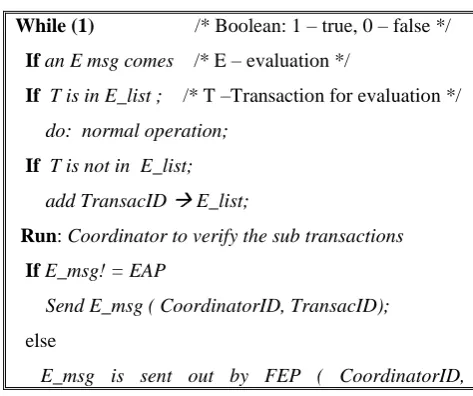
While (1) /* Boolean: 1 – true, 0 – false */
Ifan E msg comes /* E – evaluation */
If T is in E_list ; /* T –Transaction for evaluation */
do: normal operation;
If T is not in E_list;
add TransacID
E_list;Run: Coordinator to verify the sub transactions
IfE_msg! = EAP
Send E_msg ( CoordinatorID, TransacID);
else
[image:3.595.308.545.571.769.2]TransacID);
Send: verified Coord_msg (CoordinatorID,
TransacID);
end While;
Pseudo code for the primitives at LTM
At the local FEP with verified Transac_coordinator:
Send: verified sub_transac to Coordinator with CoordID
While (1)
ifa verified sub_transac comes
ifa verified sub_transac != free
Send : sub_transac
original Transactionelse
do normal execution
if ( all verified transactions are arrived)
exit;
end While;
Pseudo code for the primitives at FEP
After performing the various operations according to the above pseudo codes, run the 2PC protocol as usually. Now we can find the verified and recovered transactions at both the coordinator and participants without blocking. Why because all sub transactions are evaluated and patched up at the coordinator level. The following is the primitive which occurred at 2PC protocol.
Run 2PC
commit verified Transaction: if (verified (transact)
commits)Send: success
all participantsend if;
Pseudo code for 2PC protocol primitive
3.4
Execution Methodology of R-FEP
Let us examine how the FEP algorithm works. Consider a scenario that the M1’s coordinator is at site X, M2’s coordinator is at site Y, C1’s coordinator is at site Z, C2’s
coordinator is at site W, and C3’s coordinator at site Y. The order of commit is as follows: M1, M2, C1, C2, and C3. Here we consider the status as malevolent transactions and the transactions deviated by malevolent transactions.
At Site X: (Sx):
M1: Read (m): Write (m): Prepare: Commit;
C1: Read (m): Read (n): Write (n): Prepare: Commit;
At Site Y: SY:
M2: Read (o): Write (o): Prepare: Commit;
C3: Read (o): Read (p): Write (p): Prepare: Commit;
At Site Z: SZ:
[image:4.595.73.543.543.741.2]M2: Read (q): Write (q): Prepare: Commit; C1: Read(r)
|| C2: Read (q): Read(s) || C1: Write(r) || C2: Write(s) || C1: prepare || C2: prepare || C1: Commit; || C2: Commit; At Site W: (SW):
M1: Read (t): Write (t): prepare: Commit; || C2: Read (u) ||
C3: Read (t): Read (v) || C2: Write (u) || C3: Write (v) || C2: prepare || C3:prepare||C2: Commit; ||C3: Commit;
This process is shown in a simple diagrammatic instance which is depicted in the Fig. 4. It shows how the coordinator at the site manages the participants according to 2PC protocol.
Each transaction is habituated to global commit, why because the environment is distributed and the sub transactions are at different sites.
Fig 4: The coordinator and participant instance in distributed 2PCprotocol
Now, the execution methodology starts when two evaluation messages are transferred, in parallel to the LTM located at site X and site Y respectively. The transaction M1’s coordinator is located at site X receives the evaluation messages and add to M1’s prob_item_list. Another transaction C1 is also located at site X and transaction M1 is having impact at site W. Site X receives the evaluation messages for M1, and adds the variables of M1at site X and site W to evaluation list and the FEP process runs. After this transaction M1 at site W receives the repaired (cleaned) sub transaction from the FEP at site X. It executes that sub transaction as part of the repair transaction for M1 and use the 2PC protocol to commit.
At the same time period, the FEP at site W receives the evaluation messages for transaction M1, the FEP’s at site Y and site Z receives evaluation messages for M2, and they perform the similar things as what the FEP done at site X. In this way the other transactions can be repaired in the mean time and completes their tasks.
3.5
Characteristics of R-FEP
An evaluation message is been sent out by a local LTM if a transaction is deviated by a malevolent one.
When a normal (good conditioned) transaction is deviated by a malevolent one (like in M), the FEP will evaluate and patches the problematic transaction at every site. It should be done according to the global commit property.
When the FEP process ends every data item which is updated (during the process) by a transaction M will be restored and the log records are updated accordingly.
4.
PERFORMANCE EVALUATION
We considered the distributed system with two storage possibilities at each site in the form of queues. The first one is the purpose of log record transactions. Second one is the purpose of processing time of each log record with the parameter 1, which is the density function for the probability
f(t) = 1 e -1 t
. The processing time for mean time repair a transaction is denoted by the parameter 2. The density function for mean time to repair is f (t) = 2 e
-2 t
. According to the Poisson distribution rate (), the probability for n
log-records within the time t is Pn (t) = ((t)n / n!) e-t, and the
distribution function for the log record is F (t) = 1- e-t. Based on the FEP model the performance can be analyzed in two modes.
Mode 1: 1 < 2
Mode 2: 2 < 1
Mode 1 is for queue of log records, which are updated according to mean time repairs.
Fig 5: (a) Performance of FEP at Mode 1
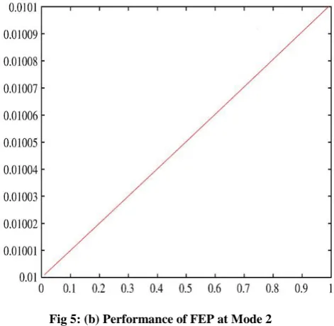
Mode 2 is for completely repaired log records. These two cases are analyzed based upon the density functions which are processed in‘t’ time with n log records at every site. Their performances have been shown in the Fig. 5 (a) as log record transactions and Fig. 5 (b) processing time for each log record.
Fig 5: (b) Performance of FEP at Mode 2
Fig 5: Performance of FEP at both Modes
[image:5.595.315.538.188.372.2] [image:5.595.315.551.456.686.2]5.
CONCLUSION
To form a model like resilient failure evaluation and patch up (R-FEP) is challenging task. We have exemplified this problem in distributed database environment. This problem have some novel principles like: (a) it is completely distributed, has no failures and also bears malevolent attacks on systems and network links. (b) The newly entered transactions can continue their activities during this FEP process. (c) FEP can be performed at each participating site, where the sites are communicating with each other. (d) This model is apparent and works with commercial DBMSs to build resilient applications. We hope that we have given an important methodology towards distributed transaction applications in the context of deviated situations.
6.
REFERENCES
[1] Stefano Ceri and Giuseppe, Distributed Databases Principles and Systems. India: Tata McGraw-Hill, 2008, pp. 176 -178.
[2] M.R. Adam, Security-control methods for statistical database: a comparative study, ACM Computing Surveys 21 (4) (1989).
[3] P.P. Griffiths, B.W. Wade, An authorization mechanism for a relational database system, ACM Transactions on Database Systems 1 (3) (September 1976) 242–255. [4] S. Jajodia, P. Samarati, V.S. Subrahmanian, E. Bertino, A
unified framework for enforcing multiple access control policies, Proceedings of ACM SIGMOD International Conference on Management of Data, May 1997, pp. 474–485.
[5] V. Atluri, S. Jajodia, B. George, Multilevel Secure Transaction Processing, Kluwer Academic Publishers, 1999.
[6] D.E. Denning, An intrusion-detection model, IEEE Transactions on Software Engineering SE-13 (February 1987) 222–232.
[7] Teresa Lunt, Catherine McCollum, Intrusion detection and response research at DARPA, Technical Report, The MITRE Corporation, McLean, VA, 1998.
[8] B. Mukherjee, L.T. Habergeon, K.N. Levitt, Network intrusion detection, IEEE Network (June 1994) 26–41. [9] P. Ammann, S. Jajodia, P. Liu, Recovery from malicious
transactions, IEEE Transactions on Knowledge and Data Engineering 15 (5) (2001) 1167–1185.
[10] P. Liu, P. Ammann, S. Jajodia, Rewriting histories: recovery from malicious transactions, Distributed and Parallel Databases 8 (1) (2000) 7–40.
[11] David Lomet, Zografoula Vagena, Roger Barga, Recovery from “bad” user transactions, SIGMOD '06: Proceedings of the 2006 ACM SIGMOD International Conference on Management of Data, ACM Press, New York, NY, USA, 2006, pp. 337–346.
[12] T. Chiueh, D. Pilania, Design, implementation, and evaluation of a repairable database management system, Proc. Annual Computer Security Applications Conference, 2004.
[13] Yanjun Zuo, Brajendra Panda, Damage Discovery in Distributed Database Systems, 2004, pp. 111–123. [14] S.P. Shieh, V.D. Gligor, on a pattern-oriented model for
intrusion detection, IEEE Transactions on Knowledge and Data Engineering 9 (4) (1997) 661–667.
[15] R.E. Strom, S. Yemini, Optimistic recovery in distributed systems, ACM Transactions on Computer Systems 3 (3) (August 1985) 204–226.