© 2018, IRJET | Impact Factor value: 6.171 | ISO 9001:2008 Certified Journal | Page 1982
Increasing in Productivity by Using Work Study in a Manufacturing
Industry
Shantideo Gujar
1, Dr. Achal S. Shahare
21
Student, Department of Mechanical Engineering, G. H. Raisoni Academy of Engineering and Technology, Nagpur,
2Professor, Department of Mechanical Engineering, G. H. Raisoni Academy of Engineering and Technology,
Nagpur,
---***---Abstract -
Productivity increase by means of a workstudy in a manufacturing industry is the area of interest in this project. The project was conducted live, where in numerous types of tools and techniques were employed to improve the efficiency and productivity of industry. In essence, our project deals with small-scale manufacturing industry. This concerned company in the project manufactures and supplies sheet metal components, including cyclones, electrical panel, stainless steel online humidification system and its components, and controlling panel. In addition, the company is a vendor of Nail Strip Jumbo, which is utilized in ginning machines. This live project applied work study methods to improve the practices in the industry, in addition to ascertaining and rectifying problems associated with the production process. The employment of such techniques improved production by reducing production time and processes involved, as well as an increase in the production rate. This project highlights the advantages of adopting such an efficient process.
Key Words: Production Time, Productivity, Work Study,
Work Measurement & Fatigue
1. INTRODUCTION
This company is Manufacturer and supplier of sheet metal component and also vendor of Nail Strip Jumbo which is use in ginning machine. When demand is high of this product, then the firm has to increase productivity. This work takes initiative to implement method study techniques to improve the work process in order to meet the demand. In production department there is some unwanted work process is done which is taking extra time, extra effort as well as increasing the cost of product and worker affected some unwanted fatigue, so the industry not able to improve productivity. One of the most powerful tools to eliminate this and improving productivity is WORK STUDY. The study examined the problems associated in the production in the perspective of work study which can reduce the production time & unwanted fatigue.
Work Study Definition: Work study may be defined as the analysis of a job for the purpose of finding the preferred method of doing it and also determining the standard time to perform it by the preferred (or given) method. Work study, therefore, comprises of two areas of study: method
study (motion study) and time study (work measurement).
Role of Work Study in Improving Productivity: In order to understand the role of work study we need to understand the role of method study and time study.
Method study (also sometimes called Work Method Design) is mostly used to improve the method of doing work. It is equally applicable to new jobs. When applied to existing jobs and existing jobs, method study aims to find better methods of doing the jobs that are economical and safe, require less human effort, and need shorter make-ready / put-away time. The better method involves the optimum use of best materials and appropriate manpower so that work is performed in well organized manner leading to increased resource utilization, better quality and lower costs. It can therefore be stated that through method study we have a systematic way of developing human resource effectiveness, providing high machine and equipment utilization, and making economical use of materials.
Time study, on the other hand, provides the standard time, that is the time needed by worker to complete a job by the standard method. Standard times for different jobs are necessary for proper estimation of
Manpower, machinery and equipment requirements.
Daily, weekly or monthly requirement of materials.
Production cost per unit as an input to better make or buy decision.
Labor budgets.
Worker’s efficiency and make incentive wage payments.
© 2018, IRJET | Impact Factor value: 6.171 | ISO 9001:2008 Certified Journal | Page 1983
Fig: Work Study
Method study procedure. This procedure involves seven basic steps as follows:
1. Select: - the work to be studied.
2. Record: - all the relevant facts about the present method.
3. Examine: - the facts critically and in ordered sequences, using the techniques best suited to the purpose.
4. Develop: - the most practical, economic and effective method having due regard to all contingent circumstances. 5. Define: - the new method so that it can always be identified
6. Install: - The method as standard practice 7. Maintain: - the method by regular routine checks.
2. PROBLEM DEFINITION
2.1 Introduction about industry:
GUKSS Industries is part of JADHAO GROUP, it is Manufacturer and supplier of sheet metal component - cyclones, electrical panel, stainless steel online humidification system & part, controlling panel. It is also supplier of ginning equipments.
Company Profile:
Name: - GUKSS INDUSTRIES.
Address: - D - 23/2, MIDC AREA, near paturkar plastic, Amravati, Maharashtra, 444605, India
Nature of Business: - Manufacture / Supplier
Phone No: - 9422916971, 0721-2521019
Fax No: - +91-0721-2521019
Email: - [email protected]
Higher Authority: - Mr. Sanjay S. Supe Weekly off: - Monday
Number of Employees: - 40 Company Product and Service:
• Control Panel Humidification Plant Manufacturers.
• Electrical Control Panel Manufacturers.
• Humidification System Manufacturers.
• Ginning Equipments.
• Metal Sheet Component Dealers.
• Sheet Metal Part for Electric Industry Manufacturers.
• Sheet Metal Pressed Component Electrical Manufacturers & Industrial Manufacturers
2.2 Problem Statement:
The company is a vendor of Nail Strip Jumbo, which is utilized in ginning machines. An increase in demand must be complemented by the capability to increase productivity.
The production department was identified to have certain work processes that could be made reductant, as these steps consumed extra time and extra effort, in addition to increasing the cost of its product. Moreover, these processes resulted in worker’s fatigue, which proved as a damper to improvement of productivity.
2.3 Objectives of Project
• Reduced machine idle time.
• Increase productivity.
• Reduce worker’s fatigue.
• Redesign jig.
• Establish the standard performance methods and standard cycle time involved
• Optimally use equipment and manpower.
• Eliminate wasteful efforts, as well as useless handling material.
3. LITERATURE REVIEW
© 2018, IRJET | Impact Factor value: 6.171 | ISO 9001:2008 Certified Journal | Page 1984 Mayank Dev Singh conducts research “To Improve
Productivity by Using Work Study & Design a Fixture in Small Scale Industry". Furthermore, he uses the Pro-E model software for model testing and developing a new model.
Mihir B Patel and Prof. Dr. Hemant R. Thakkar have worked on “Reducing Manufacturing Cycle Time of Milk Tanks by Work Study Technique in Small Scale Fabrication Industry.”Work study techniques are expensive to implement in small-scale industries. However, this method gives better results than any other technique. These techniques not only help reduce the cycle time, but also have proved useful in numerous other departments in industry such as inventory control, productivity, quality, labor work, and at various machines in a machine shop to develop process variation.
Rishabh Mishra explored “Productivity Improvement in Automobile Industry by Using Method Study.”
He established improvements on the basis of the method study, work procedure, and proper utilization of machine and material. His study advanced the prevailing process by reducing transportation and worker’s fatigue.
Dr. M. P. Singh worked on “Improvement in Process Industries by Using Work Study Methods: A Case Study.”His study was concerned with the battery manufacturing plant. He observed that the battery plant was not using optimum layout, which had potential for improvement. Various layout and method study tools were applied and flow process charts, flow diagrams and existing layouts were prepared. Novel technologies were applied to lessen production cost, process time, cost, and energy consumption.
Prathamesh P. Kulkarni researched on “Productivity Improvement through Lean Deployment and Work Study Methods.” He concluded that critical lean tools when effectively combined with Work Study Methods could form a unique leaner system, which will provide a universal solution for any type of industry having any sort of problem regarding productivity.
Ravikumar Kamble investigated “Productivity Improvement at Assembly Station Using Work Study Techniques.” The unwanted motion involved in the operation of assembly has been substantially reduced by designing assembly table, fasteners tray, and design of proper work place layout.
4. WORK STUDY
4.1 Select
[image:3.595.309.565.118.354.2]Nail Strip Jumbo is a product was selected for work study. Nail strip jumbo use in cotton ginning machine.
Fig 4.1: - Cotton Ginning Machine
Fig 4.2: - Schematic Diagram of Cotton Ginning Machine
This figure is shown all main components of cotton ginning machine. Spiked roller is made up of Nails Strips, and this nails strips are mounted on roller’s periphery. The large clumps of dried cotton are loosened with spiked roller and also extract the largest pieces of foreign material from the cotton.
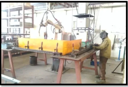
In below figure 4.3 shown the workstation of nails strip jumbo. In this figure you can see, two work tables are operated by one operator. Robotic CO2 welding machine place at the center of two work tables which is welding nails on first table and then on second table and this cycle repeats. CO2 welding machine have control panel which use to give command of start and stop and also for programming
[image:3.595.309.557.577.746.2]© 2018, IRJET | Impact Factor value: 6.171 | ISO 9001:2008 Certified Journal | Page 1985 4.2 Information Collection and Record
In this method record the relevant facts about the job by
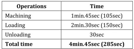
direct observation and discussion with supervisor and worker. Collect such additional data as may be needed from appropriate sources.Operations Time
Machining 1min.45sec (105sec)
Loading 2min.30sec (150sec)
Unloading 30sec
Total time 4min.45sec (285sec)
[image:4.595.46.276.158.242.2]
Table 4.1:-Existing Cycle Time. (As per company record)
Standard time of existing method is 4.45min
By using existing method company produce 100 pieces in 8 hours shift.
Production per hours of nails strips jumbo: - 14pic... (As per company record)
4.2.1 Flow process chart of Nail-Strip Jumbo
The flow process chart 4.1 of existing method is shown below. You can see from the chart all process divide into 3 main operations,1) Loading 2) Machining & 3) Unloading. The frequency of each process is shown in summary.
Summary
Process Symbol Frequency
Operation 8
Transportation 3
Inspection 1
Delay 1
Chart 4.1:- Flow process chart of existing method
4.2.2 Multiple Activity Charts
We already seen one operator work on two work table means operator prepare first work table and start the welding machine and then while welding operation performing on first work table, operator prepare second work table for the next cycle.
The efficiency of worker is not same for all day. So observation is carried out at different working time on different day. Observations were taken by using mobile video recorder and then analysis all videos and find out time required for each operation. Then I was taken average time required for 3 cycle and made multiple chart 4.2. In this chart I used mean of observed time of each operation.
Operator Machine
Descripti
on Time min Symbol Description Time min Symbol
Loading
1st job
2.05 Idle 2.05
Loading
2nd job
2.15 Machining
1st job
Idle
1.45
0.30
Unloadin
g 1st job
0.28 Machining
2nd job
1.45
Loading
3rd job
2.25 Idle 1.08
Unloadin
g 2nd job
Idle
0.25
1.20
Machining
3rd job
1.45
Unloadin
g 3rd job
0.25 Idle 0.25
Total time 9.23 min. Total time 9.23 min.
Idle =
Working =
Subject Cycle time (min) Idle time (min)
Operator 9.23 1.20
Machine 9.23 4.08
© 2018, IRJET | Impact Factor value: 6.171 | ISO 9001:2008 Certified Journal | Page 1986 From the chart 4.2 we see the real idle time of machine
and operator for the 3 job All this data were used for examined the process and find the drawback or problems related to old process.
4.3 Examine
After recorded all facts about existing method now find the true reasons underlying each event and to make a systematic list of all the possible improvements for later development in new and improved method. In table 4.2 shown the observed time required for each operation. Data taken from chart 4.2
Sr.N
o Process Time for job (in min.) observed Average
time
1 2 3
1 Machining 1.45 1.45 1.45 1.45min
(105 sec) 2 Unloading 0.28 0.25 0.25 0.26
3 Loading 2.5 2.15 2.25 2.15min
[image:5.595.37.287.239.347.2](135 sec)
Table 4.2:- Observed time for each process
We can see in chart 4.2; Machine is idle while loading operation. So we can reduce machine idle time if we reduce loading time. The loading operation does by manually and we can see from the table 4.2, times required for this operation more the other operations. There is possibility of improvement and reducing loading time.
To analysis loading operation, it is breakdown into elements and measured the time for each element. Following are elements of loading operation:
1. Pick up the strip.
2. Place that strip on fixture and clamp it. 3. Pick up nails.
4. Placing that nails in holes of strip & adjusting nails in right position it.
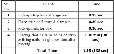
In table 4.3, I was taken average observations time of each element of loading operation.
Sr.
no. Elements Time
1 Pick up strip from storage box 0.15 sec
2 Place strip on fixture & clamp it 0.20 sec
3 Pick up nails for box 0.10 sec
4 Placing that nails in holes of strip
& Bring nails in right position after placing
1.30 min (90 sec)
Total Time 2.15 (135 sec)
Table 4.3:- Time required for each element of loading operation
From table 4.3 we can see that time required for the placing nails in holes of strip & Bring nails in right position after placing is more. Placing nails in holes of strip is simple task and it should require 2sec per nail. In one strip 24 nails are use, time should be requires for this task is:
2 × 24 = 48 sec OR maximum 1min
But we seen in the table 4.3 the time required for this task is 1.30 min. it means 30 to 42 sec required for bring nails in correct position.
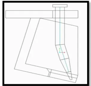
Jigs is use for guide and hold the work piece, here nails are work piece. Bring nails in right position after placing or inserting nails in the holes of strip and keep all nails at that position, this is the work of Jig. But we have seen operator do that work of bring nails in right position after inserting nails in the holes of strip. From that I made conclusion of the existing design of Jig is faulty
[image:5.595.314.550.310.448.2]
Fig 4.4: - Drawback Existing Jig
Here jig is use to guide and hold nails, and we all known nails have cylindrical shape. Sothere are chances of nails get rotate along their axis. We can see in the above figure jig is not guide and hold lower end of the nails and it is insufficient to restrict nails rotation along their axis after inserting nails. So that’s why operator brings the nails in correct position. This is increase cycle time, idle time of welding machine and fatigue of operator. Due to faulty Jig design, one extra task of operator increase and this task reduce efficiency operator because of he have to position all 24 nails after insert. This makes cause of lower production. To reduce cycle time, idle time of machine and operator’s fatigue I have to develop new Jig design.
4.4 Develop
Now we know the problem in existing method. The problem is jig design, a cause of it increase cycle time, and also increase idle time of welding machine and fatigue of worker.
4.4.1 Design Consideration in Jigs:
[image:5.595.42.279.602.715.2]© 2018, IRJET | Impact Factor value: 6.171 | ISO 9001:2008 Certified Journal | Page 1987 • Nails-Strip should be easily removed from Jig.
• Nails should be stable when it is placed in jig.
• Positioning nails accurately, maintains relationship and alignment with strip.
[image:6.595.354.507.160.304.2]New design should be prevent motion of nails along and around X, Y, Z during machining and also prevent wrong loading of nails by fool-proofing. It should be provide self positioning to nails. For that I had used shape and profile of nails.
Fig 4.5: - Nail and its Shape & Profile
4.4.2 Dimensions of New Design
[image:6.595.90.227.217.367.2]The product has been drawn by using Cero parametric 3.0.
Fig 4.6: - Front View (all dia. in mm)
Fig 4.7: - Side View (all dia. in mm)
Above figures 4.6 and 4.7 are shown front view and side view of new design. I already mentioned that in strip use 24 nails but here I shown jig design only for one nail.
You can see in figure 4.8, how I was used shape and profile of nails to make a fool-proof jig design.
Fig 4.8: - Correct Nail Position (properly insert)
In figure 4.8 shown conditions when operator insert nail in correct position. You can see that jig design follow the nail profile.
Depth from font side of the jig is nearly as height of nail. And hence nail insert properly. In figure 4.7 you can see depths of jig on both side from front and back are different and this different achieved by welding the jig at 75 degree with the base plat on which the strip is clamp.
[image:6.595.74.247.445.571.2]When operator insert nail in wrong position that time due to the less depth of jig at the back side than the height nails, nails don’t insert in the jig completely and top portion of nails is remains out of jig. This condition is shown in followed figure 4.9.
Fig 4.9: - Wrong Nail Position (improperly insert)
[image:6.595.331.534.520.703.2]© 2018, IRJET | Impact Factor value: 6.171 | ISO 9001:2008 Certified Journal | Page 1988 seeing top portion of nails-strip and it does not required to
check at bottom and that makes inspection easy and fast.
To restrict the movement of nails along there axis, I used shape and profile of nails. Nails have cone like shape and you had seen the profile of nail in above figure 4.5, this nails get bend from the lower end. For prevent movement of nails along there axis I use two ribs which make v shape pocket that follows shape of nails, shown in below figure 4.9.
[image:7.595.334.530.128.293.2]In above figure 4.9 you can see how ribs are welded to make v shape which is match the shape of nails. How this v shape and slot helps to restrict the movement of nails along there axis shown in followed figure 4.10.
Fig 4.10: - How Slot and Ribs Restrict Movement of Nail along there Axis
Due to the v shape of jig nails get self alignment and self position when operator inserts nails. This is save the time of positioning of nails.
To check design of jig, I made working model of jig for 8 nails .Model is shown in figure 4.11.
Fig 4.11: - Working Model of Jig
Then I was tested working model of jig to find out it is satisfying the design consideration or not.
[image:7.595.70.246.267.433.2]For find out the design is foolproof or not, I was insert nails in different way. After testing I was found that design is foolproof, shown in figure 4.12.
Fig 4.12: - Testing of Working Model
The above figure 4.12 is shown one nails position in wrong way and other position in correct way. Nail which is positioning in way wrong, it is not insert properly in jig and some top part of nail remains out from jig. Nail which is positioning in correct way, it is inserted properly in jig. Both conditions are shown in above figure.
After test I was found that this design of jig satisfying all design consideration. Nails get self position after inserting in the jig. It is fast enough and requires least amount of effort. Nails-Strip is easily removed from jig.
Then I find time required for task of Placing that nails in holes of strip & Bring nails in right position after placing, this task is shown in table 4.3. The new jig design completely eliminated the task of bring nails in right position. I performed task of placing that nails in holes of strip number of time and observed time required for the task. From observation I find out the time required for 8 nails are 15 sec, means 2 sec per nail. And for 24 nails time required is 48 sec or maximum 1 min. I consider 1 min for next calculation.
4.5 Measure and Define.
After develop new method we have to define the amount of work involved and standard time required to do that particular work are estimated.
[image:7.595.40.287.569.704.2]© 2018, IRJET | Impact Factor value: 6.171 | ISO 9001:2008 Certified Journal | Page 1989 Summary
Process Symbol Frequency
Operation 7
Transportation 3
Inspection 1
Delay 1
Chart 4.3:- Flow process chart of new method
You can seen from this chart the new jig design completely eliminated the task of adjust nails in right position & the frequency of operation task is become 7 shown in summary.
Now define standard time required to do that particular work are estimated. For that we have to break the process into elements. I already break the process into element in previous steps.
This process has mean elements following are those:
Machining Unloading Loading
Loading operation break into sub elements
• Pick up strip from storage box • Place strip on fixture & clamp it • Pick up nails for box
• Placing that nails in holes of strip
I already find time required for each element in previous steps, and it shown in table 4.2 &4.3
Elements Time
Machining 1min 45sec (105 sec)
Unloading 26 sec
Sub Elements of Loading
Pick up strip from storage box 15 sec
Place strip on fixture & clamp it 20 sec
Pick up nails for box 10 sec
Placing that nails in holes of strip 1 min (60 sec)
Total time for Loading 1min 45sec (105 sec)
[image:8.595.51.262.77.549.2]Total time for Process 3min 56sec (236 sec)
Table 4.4:- Time required for each element
From the above table 4.4 we can see the time required for loading operation get reduce because you have seen in previous step that the new jig design is completely eliminated the task of bring nails in right position. In table 4.2 shown old loading time 2.15min (135 sec)
From table 4.4 we got observed time, 3.56 min or 236 sec per cycle. Now to covert observed time into basic or normal time, multiple observed times by rating factor. Performance rating was found by using Westing House Method, it is 100%
To determine the standard time, for that the various allowance are added into the normal time. Allowance added like Relaxation allowance and other operator’s personnel needs such as drinking water, taking tea, going to toilet etc.
After discussion with supervisor we add 20 sec in per cycle for various allowances in observed time to get standard time
Standard Time = Observed time + Allowance Standard Time = 236 + 20
© 2018, IRJET | Impact Factor value: 6.171 | ISO 9001:2008 Certified Journal | Page 1990
5. RESULT
5.1 Time Saved behind One Cycle
The new standard time of new method is 4.16 min per cycle and existing standard time is 4.45 min per cycle. If we compare the both new and existing standard time, we can see that new standard time is less than existing standard time by 29 sec.
Means 29 sec saves behind each cycle or each piece.
Time Saved in 8 Hr
The existing production in 8 hr shift is 100 piece of Nails-Strip Jumbo. The total time save by new standard time in 8 hr is
100 piece × 29 sec ... (29 saved times behind on cycle)
2900 sec or 48.20 min
2900 sec or 48.20 min save by new method.1
5.2 Production Increase
To calculate how much production increased by new method, we have to divide time saved in 8 hr by new standard time. By this we get how many pieces produce in saved time.
Time saved in 8 hr = 48.20 min & New standard time = 4.16 min.
= 48.20 ÷ 4.16 = 11.32
= 11 pieces
By New method total production is increase by 11 pieces.
The total production is increase in percentage.
…. (Existing production in 8 hr 100 pieces) = 11%
Total production increase by 11%.
5.3 Reduce Idle Time
In existing method idle time of the machine is more. In this method loading time is more than machining time.
But in new method, machining time is reduced due to the new jig design. And the machining time and the loading time become same. Because of it the idle time is reduced.
Time required for loading and machining operation of existing and new method shown in below table.
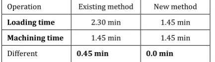
Operation Existing method New method
Loading time 2.30 min 1.45 min
Machining time 1.45 min 1.45 min
[image:9.595.327.544.83.146.2]Different 0.45 min 0.0 min
Table 5.1:-Loading & Machining Time of Existing and New Method
From the above table 5.1 we can see time different of two operations of existing and new method. The time different of existing method is 0.45 min. means after completing machining operation operator still loading workpiece on next table and hence machine is idle for 0.45 min. And in the new method time different is 0.0 min, hence machine is not idle.
5.4 Reduce Worker’s Fatigue
Adjusting nails in right position is time consuming and tiring. Due to this operator get exhausted by physically and mentally. But we can see from the chart 4.1 & 4.5; in new method this task is eliminated by using new jig design. This reduces the worker’s fatigue.
6. CONCLUSION
Work study gives lot information about existing method and this information helps to find out drawback and possible improvement in existing method. By eliminating drawback and improvements are found and adopted into a new method, called better method. This better method increase productivity, reduces worker’s fatigue, reduce the losses and improve the quality.
In this project the new jig was developed which is helps to increase productivity by 11% and also reduce worker’s fatigue. It will also reduce the losses and will improve the quality.
REFERENCES
Mayank Dev Singh, Shah Saurabh K, Patel Sachin
B, Patel Rahul, “To improve productivity by using work study and design a fixture in small scale industry”, International Journal on Theoretical and Applied Research in Mechanical Engineering 2319 – 3182, Volume-1, Issue- 2, 2012.
Mihir B Patel, Prof. Dr. Hemant R. Thakkar, they work on “Reducing Manufacturing Cycle Time of Milk Tanks by Work Study Technique in Small
Scale Fabrication Industry.”
(DOI:10.15680/IJIRSET. 2015. 0412163).
© 2018, IRJET | Impact Factor value: 6.171 | ISO 9001:2008 Certified Journal | Page 1991
Dr. M. P. Singh, research on “Improvement in Process Industries by Using Work Study Methods: A Case Study” (Volume 7, Issue 3, May–June 2016, pp.426–436, Article ID: IJMET_07_03_038).
Prathamesh P. Kulkarni research on “Productivity Improvement Through Lean Deployment & Work Study Methods” (Volume: 03 Issue: 02 Feb-2014 eISSN: 2319-1163 | pISSN: 2321-7308).