http://dx.doi.org/10.4236/jemaa.2014.612037
Toroidal Coil in Measuring Alternating
Current at a Distance
Seppo Mäkinen
School of Technology, Vaasa University of Applied Sciences, Vaasa, Finland Email: [email protected]
Received 1 July 2014; revised 28 July 2014; accepted 24 September 2014 Copyright © 2014 by author and Scientific Research Publishing Inc.
This work is licensed under the Creative Commons Attribution International License (CC BY). http://creativecommons.org/licenses/by/4.0/
Abstract
This article discusses the use of a toroidal coil in measuring alternating current from a straight current-carrying wire passing perpendicularly through the coil. The sinusoidally oscillating cur-rent generates a sinusoidally oscillating magnetic field in its vicinity. This, in turn, induces a sinu-soidally oscillating emf in the toroid. This (measured) emf can be used in order to calculate the magnitude of the electric current in the wire. The use of such technique might be sensitive to the location of the point at which the wire passes through the toroid. If the location is not known very precisely, this might cause errors in the value of the calculated current. We wanted to study if the result does not depend on the location of the wire at all, as is usually stated, or not. The study was done by deriving a single analytical formula for finding out the calculated current with the wire passing through any given point inside the toroid. This formula was then solved at about 2000 points inside a toroid to see if the location of the wire affects the result or not.
Keywords
Rogowski Coil, Current Transformer, Toroidal Coil, Electromagnetic Induction
1. The Model
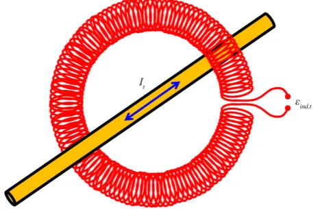
It is a common practice to use toroidal coils in measuring alternating currents at a distance. A wire carrying a sinusoidally oscillating current passes through a toroid (Figure 1), and the emf induced in the coil is measured
[1] [2]. Such a usage of toroidal coils was first suggested by A. P. Chattock already in the 19th century [3], and by W. Rogowski and W. Steinhaus some decades later [4]. Recently, scientists have been developing new mate-rials for the magnetic core of toroidal coils [5].
Figure 1. The cylindrical magnetic field lines generated by a sinusoidally oscillating current induce a sinusoidally oscillating emf in a toroidal coil around the current-carrying conductor.
with the inner surface of the toroid, the voltage will be the same as if the wire went through the geometric centre of the toroid.
We wanted to check whether this claim is correct or not.
Consider an ideal toroid of inner radius R1 and of outer radius R2, and having altogether N turns of wire. Let a straight wire carrying a sinusoidally oscillating current,
(
)
0cos
t
I =I ω φt−
pass through the toroid perpendicularly at a point whose Cartesian coordinates are
(
x y,)
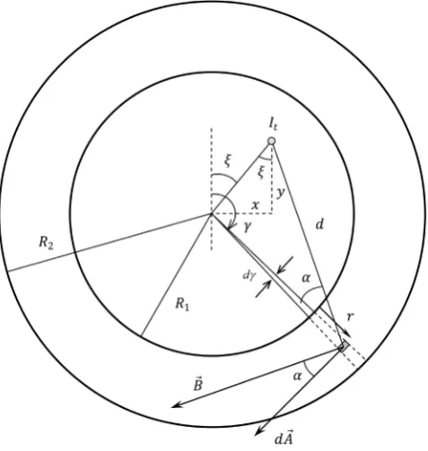
relative to an origin at the geometric centre of the toroid, as shown inFigure 2.We calculate the emf induced in the toroid by letting the angle γ vary from 0 to 2π in steps of dγ ra-dians, and integrating the contributions of all the differential amounts of turns of wire, dN, associated with each step. Because of the chosen symmetry, the magnitude of dN can be calculated simply as:
d d
2π
N = γ N
For each value of the angle γ , we integrate the contributions of all the infinitesimal area elements dA of the toroid’s cross-sectional surface. This is done by letting the variable r grow from 0 to R2−R1, and inte-grating the emfs associated with each such area element. For the magnitude of dA, seeFigure 3.
According toFigure 3, the size of a differential area element is given by:
2 2
2 1 2 1
d d 2
2 2
R R R R
A= r× × − − − −r
These two results yield that the differential amount of emf induced in the toroid when the angle γ increases by dγ radians can be calculated as:
(
)
(
)
(
)
{
}
(
)
(
)
0 0 00 0 0
0 2
dΦ d d
d d d d d cos
d d d
d d d
d d cos d cos cos
d 2π 2π 2π d
cos cos
sin d d sin d d
2π 2π 4π
B ind
t
N N N AB
t t t
I
N A N A I t
t d d t
N I
N
I t A t A
d d
ε α
µ γ µ
α α ω ϕ
µ ω ω ϕ α γ µ ω ω ϕ α γ
= − = − ⋅ = − = − = − − = − = −
∫
∫
∫
∫
∫
A B This yields:(
)
2 20 0 2 1 2 1
2
cos
d sin 2 d d
2 2
4π ind
N I R R R R
t r r
d
µ ω α
ε = ω ϕ− − − − − γ
Figure 2.The current-carrying straight conductor passes perpendi-cularly through the toroid at the Cartesian coordinates (x,y) relative to the geometric centre of the coil.
Figure 3.The cross-sectional area of the toroid is divided into differentially small elements, dA.
The Law of Cosines, when applied to our geometry, yields an expression for the ratio of cos
α
to d:(
)
(
)
(
)
(
)
(
)
(
)
2
2 2 2
1 1
2
2 2 2
1
1
2
2 2 2
1 2
1
2 cos
cos
2
cos
2
x y d R r d R r
x y d R r
d R r
x y d R r
d d R r
α
α
α
+ = + + − +
+ − − +
⇒ =
+
+ − − +
⇒ =
+
[image:3.595.199.427.385.564.2](
)
2(
) (
)
2 2 2 2 2
1 2 1 cos
d =x +y + R +r − x +y R +r
γ ξ
−Further,
1 tan x
y
ξ = −
If one combines all the results together, the emf induced in the toroid can be calculated as follows:
(
)
(
)
(
)
(
)
(
)
(
)
(
)
2 1 0 0 2 2 22 2 2 2 2 2 1
1 1 1
2π
0
2
0 2 2 2 2 1
1 1 1
2 2
2 1 2 1
d sin
4π
2 cos tan
2 cos tan
d d 2 2 ind ind R R N I t x
x y R r x y R r x y R r
y
x
R r x y R r x y R r
y
R R R R
r r
µ ω
ε ε ω ϕ
γ γ γ − − − = = − + − + − + + + − + + − × + + + + − + + − − − × − −
∫
∫ ∫
2. Results of the Calculations
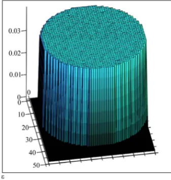
We used the mathematical software Mathcad, and solved the induced emf for a toroid and a current with the following specifications: 1 2 0 45 mm 55 mm 5000 80 A 50 Hz 0 4 p R R N I f T t ϕ = = = = = = =
[image:4.595.228.397.516.694.2]We did the calculus with a mesh of about 2000 node points inside the toroid, and solved the magnitude of 𝜀𝜀ind for each point separately. The calculation revealed that the induced emf is completely independent of the posi-tion of the wire; the induced voltage was found to be 39.6 mV for all the points, seeFigure 4.
Our analysis thus verifies the claim that the emf induced in a toroid is independent of the position of a wire passing through the toroid—at least when the wire is perpendicular to the plane of the toroid.
Note that our analysis was done simply by assuming that the current-carrying wire is extremely thin and straight, and that the wire passes through the toroid perpendicularly. In a more general analysis, one would need to consider the cross-sectional shape and dimensions of the wire, as well as the wire’s orientation relative to the plane of the toroid.
3. Conclusion
Our analysis gives confirmation to the generally stated claim that the magnitude of the measured sinusoidally oscillating current is independent of the point at which the current-carrying wire passes through the toroid. Be-sides this result, we feel that this paper yields a valuable model for solving cases with similar geometry.
References
[1] Krishnamurthy, K.A. and Raghuveer, M.R. (2001) Electrical, Electronics and Computer Engineering for Scientists and Engineers. 2nd Edition, New Age International Publishers, New Delhi.
[2] Ward, D.A. and Exon, J.La.T. (1993) Using Rogowski Coils for Transient Current Measurements. Engineering Science and Educational Journal, 2, 105-113. http://dx.doi.org/10.1049/esej:19930034
[3] Chattock, A.P. (1887) On a Magnetic Potentiometer.Philosophical Magazine, 24, 94-96.
http://dx.doi.org/10.1080/14786448708628063
[4] Rogowski, W. and Steinhaus, W. (1912) Die Messung der Magnetischen Spannung. Archiv für Elektrotechnik, 1, 141- 150. http://dx.doi.org/10.1007/BF01656479
[5] Luciano, B., Batista, T., Freire, R., Guerra, F. and de Castro, W. (2012) Current Transformers with Nanocrystalline Alloy Toroidal Core: Analytical, Computational and Experimental Studies. Materials Research, 15, 805-808.