© 2017, IRJET | Impact Factor value: 5.181 | ISO 9001:2008 Certified Journal | Page 612
Comparative Study on Flexural Strength of M-40 grade with Lapping of
Bars
1
Shivakumar Chalawadi,
2Praveen Biradar
1
P.G. Student,
2Assistant Professor, Department of Civil Engineering. BLDEA’S Engineering & Technology,
Vijayapur, Karnataka, India
---***---Abstract -
For structural engineering applications,particularly in concrete structures efforts are being made to investigate the importance of using lapping bar while using straight bar. If length of a bar is not sufficient to keep the reinforcement then lapping of two bars is necessary. Generally lapping is required at the section where minimum shear force is acting. Usually lap length provided is 40d that is 40 times the bar diameter, if both bars are having same diameter. The lap length is taken as 40 times the smaller diameter bar, when two bars of different diameters are used. Many researchers have carried out work on the concrete beam with lapping of bar at center and used M-sand as a replacement for natural sand. In the present study it is concluded that no experimental investigation was carried out for concrete beam with lapping of bars except the replacement of fine aggregate by M-sand. In the present study cube and beam specimens were tested according to the guidelines mentioned in the IS code. This study intends to test beams made of 0%, 25%, 50% and 100% lapping of bars. The compressive test was carried out on three cubes. Four beams have tested under two point loading and their failure modes and the load deflection responses are observed experimentally. The compressive strength of concrete cube casted with manufactured sand, behavior of concrete with using the manufactured sand and the effect on margin of safety in flexure on cracking strength are discussed.
Key Words: Flexural Strength, Lapping Of Bars,
Manufactured Sand, Margin of Safety, Cracking Strength.
1.INTRODUCTION
M-sand has got wide applications in the construction field and they have been using from long time. Natural or river sand is cold and exhausted particles of rocks and is available in required grades or sizes depending upon the degree of weathering. In present scenario good sand is not available easily; it is imported from a large distance places. As natural resources are exhausting very rapidly, for that we need to get some alternate particles to natural river sand. The M-sand should be of suitable gradation. The size of the particles must be ranging from 150 µm to 4.75 mm in suitable fraction. The researchers also recognized that river sand is an extensively used construction material in most of the places like construction of buildings, structures etc. Various private organization and government with non government
organizations are ready to research for getting alternative material to supplement natural river sand. He also suggests that alternative material to river sand can be M-sand [12]. Magda I. Mousa [1] showed in their study splitting failure of the concrete specimen with splice length 300 mm (25Ø) was rapid violent and occurred all along the length of the splice. It is suggested to use minimum transverse reinforcement within the splice zone to impound the failure and to control development of splitting cracks. The use of hooked end splice increased the cracking load, ultimate load and the failure was more ductile compared with the similar beam without hooks.
M. M. EL-Hawary, A. T. Kassem proposed that spice length increases the failure load, cracking load and ductility increases. Distributing stirrups with small spacing as well as splice length increases failure load, cracking load and ductility than concentrating stirrups with splice ends. The cube and beam specimens were tested according to the guidelines mentioned in the IS code. The compressive test was carried out on cubes. The beams have tested under two points loading and their failure modes and the load deflection responses are studied.
2. MATERIAL PROPERTIES
The materials detail and their various properties are mentioned in the following tables. The materials are confirms to the guidelines mentioned in the respective IS codes.
1. Cement (OPC) 2. Coarse Aggregate 3. Fine aggregate – M-sand 4. Water
[image:1.595.329.555.681.779.2]Based upon the sieve analysis test it is observed that the fine aggregate confirms to grading Zone I.
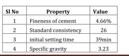
Table 1. Properties of cement
Sl No Property Value
1 Fineness of cement 4.66%
2 Standard consistency 26 3 initial setting time 39min
© 2017, IRJET | Impact Factor value: 5.181 | ISO 9001:2008 Certified Journal | Page 613
Table 2. Properties of coarse aggregate
Sl No Property Value
1 Specific gravity 2.85
2 Sieve analysis 20mm
Table 3. Properties of fine aggregate
Sl No Property Value
1 Specific gravity 2.8
2 Sieve analysis Zone I
3. METHEDOLOGY
[image:2.595.308.559.323.500.2]In order find suitable ingredients of concrete with required workability, durability and strength of concrete the mix design of concrete is very essential as economical as possible [4] and [5]. The ratio of ingredients of concrete is getting by the required performance in two states these are Plastic state and hardened state. In case of plastic state the concrete is not workable and it cannot be placed properly and compacted. Therefore the workability property plays very vital role. The procedure for mix design of concrete was carried out by referring the IS 10262 – 2009 guidelines. The mix proportion obtained for concrete grade M-40 is 1: 1.92: 2.39 (cement: sand: aggregate).The w/c ratio being 0.45.
Fig 1. Steel detailing of beam without lapping of bars
Fig 2. Steel detailing of beam with 25% lapping of bars
Fig 3. Steel detailing of beam with 50% lapping of bars
Fig 4. Steel detailing of beam with 100% lapping of bars
4. RESULT AND DISCUSSION
4.1. Compressive test
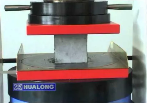
The fig 5 shows the testing of cube specimen in universal testing machine (UTM) and Table 3.6 shows the compressive strength of cubes for Trail mix of M-40 grade
[image:2.595.38.290.443.515.2]Fig 5. Testing of cube specimen
Table 1. Compressive Strength for Trial mix of M 40 grade
Grade M-40
Cement in (Kg/m3) 437
Compressive Strength in
Mpa
7 days 29 Fine
aggregate in (Kg/m3) 843
14
days 34.6 Coarse
aggregate in (Kg/m3)
1045
28
days 42.2 Water
(liters/m3) 197
4.2. Flexure test
[image:2.595.52.562.557.760.2]© 2017, IRJET | Impact Factor value: 5.181 | ISO 9001:2008 Certified Journal | Page 614 constant moment on beam. The beam was supported on two
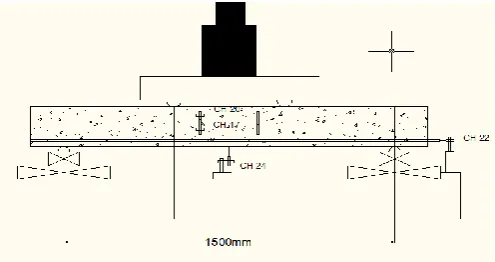
[image:3.595.308.571.238.404.2]simple supports resting on steel plates of size 200 mm x 100mm. The effective length of the beam is 1500mm.The front face of the specimen was white washed and marked with grids of size 50 mm x 50 mm to study the crack propagation. The LVDT’s and PI gauges are attached at the center and bottom of the specimen along the depth of the beam for getting the deflection values. Total four channels of gauges are attached. Channel 17 attached at the bottom of the front face, channel 20 attached at the top of the front face, channel 24 attached at the bottom face of the beam and channel 22 attached directly to the bar at one side of the beam for finding the deflection values. The deflections or settlements of the beam were measured at center, 1/3rd of the span and at ends were measured by means of LVDT’s and dial gauges. In four beams of size; 1800 mm × 200 mm × 150 mm have been tested under two point loading. The load-deflection characteristics and their failure modes and load capacity curve are studied. The result obtained has been compared with the analytical values regarding the ultimate load and cracking load and the same is shown in Table 4.1. The load deflection response is shown in Figs. 4.1.
Fig 6. Detailed setting of flexure test
Table 6. Comparison of Analytic and Experimental load strength
Cracking Load (kN) Ultimate Load (kN) An Exp
(Pcr)exp (Pcr)an
An Exp
(Pu)exp (Pu)an (P
cr) an
(Pcr
)exp (Pu)an (Pu)exp
Concrete beam without lapping
4.22 9.1 2.15 51.96 51.3 0.98
Concrete beam with 25 % lapping
4.22 5.7 1.35 51.96 35.5 0.68
Concrete beam with 50 % lapping
4.22 6.8 1.61 51.9
6 46.8 0.9
Concrete beam with 100 % lapping
4.22 7.9 1.87 51.96 48.8 0.94
The comparison of analytic and experimental cracking loads and Ultimate loads for the beams tested for M40 grade is explained below.
For the cracking load the margin of safety of 2.15, 1.35, 1.61 and 1.87 respectively for concrete beam 0%, 25%, 50% and 100% lapping. Similarly for ultimate load the margin of safety are 0.98, 0.68, 0.9 and 0.94 respectively for concrete beam 0%, 25%, 50% and 100% lapping
4.2.1. Load carrying capacity curve
Fig 7. Capacity curve
Fig 7. Indicates that failure load to percentage of steel lapping that is capacity curve. The load carrying capacity increases with increase in lapping of percentage. Zero percentage lapping of steel reinforcement is showing the maximum load carrying capacity when compared to 25, 50 and 100 percentage lapping. As the lap length is less in 25% it fails earlier when compared to 50 and 100% lap where the lap length is more
4.2.2. Load deflection characteristics
[image:3.595.38.286.368.499.2]© 2017, IRJET | Impact Factor value: 5.181 | ISO 9001:2008 Certified Journal | Page 615 Fig8. shows the combined load deflection curve for 0%, 25%,
50% and 100% lapping of bars As the load increases deflection also increases. The load and deflections directly proportional to each other. At a given load level the deflection is more for concrete beam with 25% and 50% lapping of bars as compared to concrete made with 0% and 100% lapping of bars.
4.2.3. Crack propagation
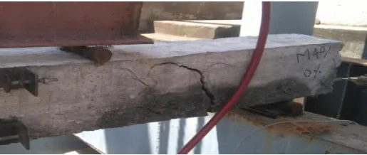
[image:4.595.36.294.300.409.2]During the test the crack profile was marked on RC beams at regular intervals and the same are represented schematically in Figs.9- 12. Initially the flexure cracks develop at the mid-span before the development of diagonal cracks. Later these cracks propagated towards the point of application of load.
[image:4.595.34.301.441.566.2]Fig 4.9. Crack profile for RC beam with 0% lapping
Fig 4.10. Crack profile for RC beam with 25% lapping
Fig 4.11. Crack profile for RC beam with 50% lapping
Fig 4.11. Crack profile for RC beam with 100% lapping
5. CONCLUSIONS
Based on the objectives derived from the literature survey in the present study and experimental work carried out in laboratory the following conclusions are drawn.
The physical properties of manufactured sand similar to natural sand.
The compressive strength of concrete cube casted with manufactured sand for 7, 21 and 28 days are found to be 29 N/mm2, 34.6 N/mm2 and 42.2 N/mm2 respectively.
For reinforced concrete beam with using manufactured sand increase in cracking and ultimate strength.
The margin of safety in flexure on cracking strength for M 40 grade concrete are 2.15, 1.35, 1.61 and 1.87 respectively for 0%, 25%, 50% and 100% lapping of bars.
The margin of safety in ultimate strength for M 40 grade concrete are 0.98, 0.68, 0.90 and 0.94 respectively for 0%, 25%, 50% and 100% lapping of bars.
At a given load level the deflection is more for concrete beam with 25% and 50% lapping of bars as compared to concrete made with 0% and 100% lapping of bars.
The load carrying capacity increases with increase in lapping of percentage.
As the lap length is less in 25% it fails earlier when compared to 50 and 100% lap where the lap length is more.
REFERENCES
1) Magda I. Mousa., (2015) “Flexural behavior and ductility of high strength concrete (HSC) beams with tension lap splice”, Structural Engineering Department, Faculty of Eng., El-Mansoura University, Egypt, Alexandria Engineering Journal (2015) 54, 551–563.
© 2017, IRJET | Impact Factor value: 5.181 | ISO 9001:2008 Certified Journal | Page 616 Reinforced with Steel Bars Exceeding the Nominal
Yield Strength” Latin American Journal of Solids and Structures 13 (2016) 945-963.
3) Seongjun Kim, Jungwoo Lee, Changbin Joh, Imjong Kwahk., (2016) “Flexural Bond Behavior of Rebar in Ultra-High Performance Concrete Beams Considering Lap-Splice Length and Cover Depth”, Scientific research publishing Engineering, 2016, 8, 116-129.
4) B.Vidivelli and T. Subbulakshmi., (2016) “Flexural Behaviour of Reinforced High Performance Concrete Beams Subjected to Bending”. American Journal of Engineering Research, e-ISSN: 2320-0847 p-ISSN: 2320-0936 Volume-5, Issue-11, pp-326-332.
5) Nimitha Vijayaraghavan and A.S. Waya., (2013) “Effects of M-sand on compressive strength and workability of concrete” International journal of structural and civil engineering research, ISSN 2319 – 6009 Vol. 2, No. 4.
6) Mani Kandhan.K.U, Sathya Kumar.N, Uthaya.K., (2015) “Mechanical properties of high strength concrete using M-sand as fine aggregate”, International Conference On Recent Trends In Engineering Science And Management ISBN: 978-81-931039-2-0.
7) Eun Suk Choi, Jung Woo Lee, Seong Jun Kim, Jong Won Kwark., (2015) “Bond Strength between High Performance Concrete and Reinforcing Bar” Scientific research publishing Engineering, 2015, 7, 373-378.
8) Yajurved Reddy M, D.V. Swetha and S. K. Dhani., (2015) “Study on Properties of Concrete with Manufactured sand as Replacement to Natural sand”, International Journal of Civil Engineering and Technology (IJCIET), Volume 6, Issue 8, Aug 2015, pp. 29-42, Article ID: IJCIET_06_08_004
9) V. Bhikshma, R. Kishore & C.V. Raghu Pathi., “Investigation on flexural behavior of high strength manufactured sand concrete” Challenges, Opportunities and Solutions in Structural Engineering and Construction – Ghafoori (ed.) © 2010 Taylor & Francis Group, London, ISBN 978-0-415-56809-8.
10) Ahmed El-Azab, Hatem M. Mohamed., “Effect of tension lap splice on the behavior of high strength concrete (HSC) beams” Housing and Building National Research Center (2014) 10, 287–297.
11) M. M. EL-Hawary, A. T. Kassem, A. M. EL-Nady., “Flexural Behavior of Rectangular Concrete Beams
with Lap Splices between Deformed and Smooth Reinforcement Bars” International Journal of Engineering Research & Technology (IJERT) Vol. 2 Issue 12, December – 2013.
12) Dr. Aswath M U., “Manufactured sand”, Professor and Head of Department of Civil Engineering, Bangalore Institute of Technology.
13) HSJQ., “Process of Manufactured sand”, China largest mining machinery manufacturer.
14) IS: 456-2000., “Code of practice for plain reinforced concrete” (Fourth revision).