© 2017, IRJET | Impact Factor value: 5.181 | ISO 9001:2008 Certified Journal
| Page 1391
THE POWER QUALITY IMPROVEMENT IN THE MODES OF OPERATION FOR
MICROGRID WITH UPQC
1
K.NAGA KISHORE,
2P.NAGENDRA,
3M. SHOBBHA
1
PG Scholor, MTECH (PE), CVRT, Andhrapradesh, India
2
Assistant Professor, Dept of EEE,Andhrapradesh, India
3
Associate Professor & HOD, Dept of EEE, CVRT, Andhrapradesh, India
---***---
Abstract:- Conceptual.Another idea for the situation,
coordination, and control of unified power quality conditioner (UPQC) in conveyed era (DG)- based network associated or self-governing microgrid/smaller scale era (µG) system has been introduced. The DG converters with capacity and the shunt some portion of the UPQC Active Power Filter shunt (APFsh) is put at the Point of Common Coupling (PCC). The arrangement part of the UPQC Active Power Filter arrangement (APFse) is associated before the PCC and in arrangement with the network. The dc connection can likewise be incorporated with the capacity system. Savvy islanding detection and reconnection technique (IsDRT) are presented in the UPQC as an optional control (UPQCµG – IsDRT).The testing issues of a fruitful joining of UPQC in a DG based matrix associated μG system are essentially, control many-sided quality for active power transfer, capacity to remunerate non active power amid the islanded mode and trouble in the limit improvement separately. For a consistent power transfer between the system associated operation and islanded mode, different operational changes are included, for example, exchanging between the current and voltage control mode, vigor against the islanding detection and reconnection deferrals, and so on. The over two plans were executed in simulink condition of the MATLAB. The reenactment comes about demonstrated that, Fuzzy controller based plan given better execution contrasted with UPQC controller based plan.
INTRODUCTION
For a consistent power transfer between the system associated operation and islanded mode, different operational changes are included, for example, exchanging between the current and voltage control mode, vigor against the islanding detection and reconnection delays. Obviously, these further increment the control intricacy of the μG systems. To stretch out the operational adaptability and to enhance the power quality in system associated μG systems, over again position and incorporation technique of UPQC have been proposed, which is named as UPQCμG. In the UPQCμG coordinated appropriated system, μG system (with capacity) and shunt some portion of the UPQC are set at the Point of Common Coupling (PCC).
The arrangement part of the UPQC is put beforethe PCC and in arrangement with the system. The dc connect is also connected to the capacity, if present.To keep up the operation in islanded mode and reconnection through the UPQC, correspondence process between the UPQCμG and μG system is specified. The control technique of the exhibited UPQCμG is improved by executing a smart islanding and novel reconnection technique with decreased number of switches that will guarantee consistent operation of the μG without intrusion. Thus, it is named as UPQCμG−IsDRT. The advantages offered by the proposed UPQCμG−IsDRT over the regular UPQC.
UPQC can repay voltage intrusion/list/swell and non active current in the interconnected mode. Thusly, the DG converter can in any case be associated with the system amid these misshaped conditions. Subsequently, it upgrades the operational adaptability of the DG converters or μG system, as it were, which is additionally explained in later segment. Shunt some portion of the UPQC Active Power Filter (APFsh) can keep up association amid the islanded mode and additionally repays the non active Reactive and Harmonic Power (QH) power of the load.
Both in the interconnected and islanded modes, the μG gives just the active power to the load. In this manner, it can lessen the control multifaceted nature of the DG converters. Islanding detection and reconnection technique are presented in the proposed UPQC as an optional control. A correspondence between the UPQC and μG is additionally given in the auxiliary control.
The DG converters may not require to have islanding detection and reconnection. The system can even work within the sight of a stage hop or contrast (inside point of confinement) between the matrix and μG. Along these lines, UPQCμG−IsDRT will have the aggregate control of the islanding detection and reconnection for a consistent operation of μG with a fantastic power benefit.
LITERATURE SURVEY
© 2017, IRJET | Impact Factor value: 5.181 | ISO 9001:2008 Certified Journal
| Page 1392
typical UPQC are to repay voltage interferences notwithstanding voltage lists/swells, consonant and reactive power pay in the interconnected mode. The UPQC will remunerate the reactive and symphonious power of the load in the islanding mode.
A.Kahrobaeianand Y.R.Mohamed[2] represented an interactive circulated era (DG) interface for adaptable miniaturized scale matrix operation in the keen dispersion system. DG units ought to be incorporated into the system operational control structure, where they can be utilized to upgrade system unwavering quality by giving reinforcement era in disengaged mode, and to give subordinate administrations (e.g. voltage bolster and reactive power control) in the lattice associated mode.
X.Yu and A.M.Khambadkone[3]presented half and half control engineering to adjust the power shared among the different interfacing inverters and streamline the system working proficiency.
T.Jimichi and H.Fujita[4]described the plan system of the dc capacitor under a voltage-list condition and proposed a control technique for the arrangement converter, which is equipped for decreasing the voltage appraisals of both the arrangement converter and the arrangement transformers.
J.Nielsenet al.[5] displayed voltage hangs are a critical power quality issue and the dynamic voltage restorer which is known as a successful gadget to alleviate voltage lists. Distinctive control strategies to remunerate voltage hangs with stage hop are proposed and looked at.
UNIFIED POWER QUALITY CONDITIONER
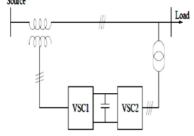
[image:2.595.329.529.105.245.2]The arrangement of both DSTATCOM and DVR can control the power quality of the source current and the load transport voltage. What's more, if the DVR and STATCOM are associated on the DC side, the DC transport voltage can be controlled by the shunt associated DSTATCOM while the DVR supplies the expected vitality to the load in the event of the transient aggravations in source voltage. The design of such a gadget (named as Unified Power Quality Conditioner (UPQC)) is appeared in figure 3.1. This is an adaptable gadget like an UPFC. In any case, the control goals of an UPQC are very not the same as that of an UPFC.
Figure 1 Unified Power Quality Conditioner (UPQC)
UPQCμG−IsDRTController Design
The diagram of the proposed UPQCμG−IsDRT controller is appeared in figure 3.6. It has an indistinguishable fundamental usefulness from theUPQC controller with the exception of the extra islanding identification and reconnection abilities.
A correspondence channel(signals exchange) between the proposed UPQCμG−IsDRT and the μGis additionally required for the smooth operation.These signals generation depend on the list/swell/intrude on/supply disappointment conditions.This errand is performed in Level2 (optional control) of the progressive control.Level 1 manages the essential control of the UPQC to play out their fundamental capacities in the interconnected and the islanded mode.The general coordination system and control technique are to enhance the power quality amid interconnected and islanded modes.
[image:2.595.321.548.505.725.2]© 2017, IRJET | Impact Factor value: 5.181 | ISO 9001:2008 Certified Journal
| Page 1393
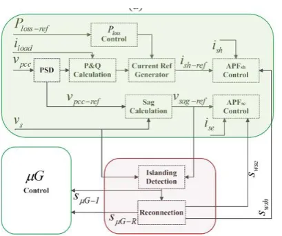
Figure 3: Block diagram of the UPQCμG−IsDRT control algorithm.
The piece chart of the UPQCμG−IsDRT control calculation as appeared in figure 3. This includes distinguishing islanding and reconnectionthat guarantees the DG converter stays associated and supply dynamic power to the load. This diminishes the control complexityof the converter and also the power disappointment probability inthe islanded mode. The five primary components of the proposed UPQCμG−IsDRT controller are:
1. Positive Sequence Detection. 2. Series Part (Apfse) Control. 3. Shunt Part (Apfsh) Control.
4. Intelligent Islanding Detection (IsD). 5. Synchronization And Reconnection
(SynRec).
On account of power quality issues, it is accounted for thatmore than 95% of voltage droops can be remunerated byinjecting a voltage of up to 60% of the ostensible voltage, with amaximum length of 30 cycles. In this manner, in view of the islanding location necessity and hang/swell/interfere with remuneration, islanding is recognized and a flag SμG− I, is additionally produced in the proposed UPQCμG−IsDRT to exchange it to the DG converters. As the APFse takes there
sponsibility for repaying voltage
hang/swell/unbalancedisturbances (contingent upon the controller), IsD calculation in the proposed UPQCμG−IsDRT can be straightforward yet very adaptable.
Then again, it will lessen the unpredictability ofislanding identification procedure or even can be expelled from all the DG converters in a μG system. A straightforward calculation that has been utilized to identify the islanding condition to work theUPQC in islanded mode. The voltage at PCC is taken asthe reference and it is dependably in stage with the source andthe DG converters, the contrast between the Vpcc-ref (pu) and
Vs(pu) is Verror. This mistake is then contrasted and the presetvalues (0.1– 0.9) and a holding up period (client characterized n cycles) issued to decide the list or interfere/islanding condition.As the consistent voltage exchange from network associated with separated mode is one of the basic errands in transitionperiod, the exchange is finished at the zero-intersection position of the APFse. In this way, no voltage variance or abrupt conditions happen.
THE ISLANDING DETECTION AND ECONNECTION TECHNIQUES
Islanding discovery is fundamental for secure and dependable operation of microgrids. Considering the connection between the power generation and the load in microgrids, recurrence may fluctuate with time while islanding happens. As a typical approach, recurrence estimation is generally used to recognize islanding condition. A novel recurrence computation calculation in view of stretched out Kalman channel was proposed to track dynamic recurrence of the microgrid. consideration because of ecological contamination and weariness of non-renewable energy source. Numerous utilities around the globe have a noteworthy entrance of DGs in their systems.As a promising creating pattern, the idea and methods of microgrids (μG) are proposed to enhance DG's utilizationMicrogrid is a sort of territorial electric power systems which incorporate DGs and power loads.
They can separate from or parallel with substantial electric power systems. Microgrid offer numerous potential advantages, for example, enhancing the unwavering quality of power supply by islanding operation amid vast electric power system blackouts, mitigating over-burden issues by permitting a piece of the power system to purposefully island, et cetera. Be that as it may, there are likewise many issues to be settled before μGs turned out to be indispensable piece of the utilities, for example, how to accomplish high power quality, proficiency, and security. Particularly, the most concerned issue is the islanding which alludes to a condition that microgrid has an autonomous powering to an area despite the fact that the Microgrid has been separated from the system.
© 2017, IRJET | Impact Factor value: 5.181 | ISO 9001:2008 Certified Journal
| Page 1394
neighborhood systems. Nearby systems can be separated into latent and dynamic identification methods.Remote islanding recognition procedures depend on the correspondence amongst utilities and DGs. Supervisory control and information procurement has been utilized to decide if the dispersion system is islanded or not. These strategies are solid however not financial to execute for little systems.As for the nearby procedures, the center of aloof strategy is that a portion of the system parameters (voltage, recurrence, and so forth.) change significantly with islanding yet very little in typical running when associated with lattice.
This character can be useful in islanding discovery by persistently observing the parameters of the system without bringing unsettling influence. Be that as it may, this strategy would cause extensive nondetection zones in light of the fact that islanding can't be recognized under an ideal match of generations and loads in the island system. Dynamic methods straightforwardly cooperate with the power system operation by presenting bothers. These little bothers will bring about a huge change in system parameters when the DG is islanded while the change will be insignificant when the DG is associated with the network. It has littler nondetection zones yet aggravates the system. The most ordinarily utilized techniques are receptive power send out mistake discovery strategy, impedance estimation strategy, dynamic recurrence float, and programmed stage shift.For the detached location technique, one of the basic aloof methodologies depends on the estimation of voltage vector and recurrence of the regular coupling point continuously.
[image:4.595.321.562.104.332.2]Variety in voltage and recurrence from its typical esteem demonstrates the event of islanding in many conditions. Countless are accessible for the recurrence estimation in light of digitized tests of system voltage, techniques, for example, discrete Fourier changes, traditional Kalman channel, and stage bolt circle. For the most generally utilized calculations, discrete Fourier changes may prompt mistakes because of spillage and picket-fence impacts. In the interim, it is not perfect when the system is nonstationary since it requires substantial estimation windows and it is delicate to low flag to-commotion proportion. The μG inserted in dispersion systems has advanced overwhelmingly to help meet the load development in existing networksas appeared in figure 4..
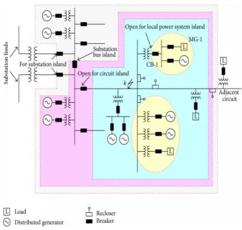
Figure 4.: Typical topologies of μG
The most critical component of μGs is that they can separate from or parallel with the range electric power system. The arranged μG in figure 4.1 might be a neighborhood electric power system island, Circuit Island, or substation island. By and large, a progress to-island mode can be a consequence of planned or unscheduled occasions. Booked advances are deliberate occasions for which the time and span of the arranged island are settled upon by all gatherings included.
Unscheduled changes are accidental occasions that are regularly started by loss of region power system or gear disappointment, and the μG should be naturally sectionalized from the territory power system by islanding defensive relay.As appeared in figure 4.2 for a blame outside to the arranged island μG-1, it is normal that the DG ought to be detached from the zone electric power system at the earliest opportunity. Subsequently, the quick electrical switch CB-1 is required to be open for the blame. Clearly, learning of the working states of the system preceding islanding and control of those working conditions will encourage the smooth exchange to a purposeful island, especially in light of unusual occasions.
© 2017, IRJET | Impact Factor value: 5.181 | ISO 9001:2008 Certified Journal
| Page 1395
[image:5.595.330.544.106.380.2]islanding recognition is one of the key issues for security and control of μG.
Figure 5: Schematic diagram of protection and control of microgrids.
The other favorable position is that, IsD and SynRec techniques have been did as an optional control in Level
2, i.e, these can likewise be included traditional UPQC system asan extra square to change over it to UPQCμG−IsDRT.
[image:5.595.54.264.141.352.2]It is to benoted that the proposed UPQCμG−IsDRT will be useful to meetthe required propelled lattice mix highlights as mentioned.The other preferred standpoint is that, IsD and SynRec strategies have been done as an auxiliary control in Level 2, i.e, these can likewise be included customary UPQC system as an extra piece to change over it to UPQCμG−IsDRT. It is to be noticed that the proposed UPQCμG−IsDRT can be useful to meet the required propelled network joining highlights as specified
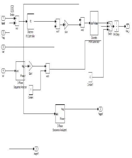
Figure 6 Simulink model for UPQC
Figure 7: Simulation model of PI controller for UPQC
SIMULATION RESULTS
[image:5.595.331.545.417.673.2]© 2017, IRJET | Impact Factor value: 5.181 | ISO 9001:2008 Certified Journal
| Page 1396
[image:6.595.52.264.100.229.2].
Figure 5.5: voltage at the point of common coupling
[image:6.595.338.539.270.371.2]The voltage at the point of common coupling and it is always in phase with the source and DG converters. The difference between Vpcc and Vs is error is Verror as shown in figure 5.6.
Figure 8: The voltage error (Verror) between the Vpcc and the Vs
This error is compared with the preset values and a waiting period is used to determine the sag or interrupt or islanding conditions. From the figure 9 and figure 5.8 it is seen that if the error (Verror) between Vpcc and the Vs lessthan or equal to 60% the sag could be compensated upto 50 cycles or If the Verror is in the range of60%-90% then the compensation will be for 30 cycles otherwise (Verror>90%). It will be interrupt or block out for islanding after one cycle.
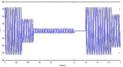
Figure 9: Source voltage during operations using both PI and fuzzy controller
Figure 10: Wave form for voltage sag
The three phase fault created in the system by using blocks of the power simulation library in MATLAB, which is shown in figure 5.8.
[image:6.595.51.263.329.451.2]Figure 5.9: Switch 2 during modes of microgrid operation
Figure 5.9 shows the switch positions (0 for open and 1 for close) during the simulation period from 0 to 2 s where both the interconnected and islanded modes are observed.
[image:6.595.334.545.476.572.2]Figure 11: Switch 3during modes of microgrid operation
Figure 10 and figure 11 shows that switch 2,switch 3 is in operating condition respectively in the islanding and grid connected modes of operation for microgrid. When the faults and voltage sag is obtained in the Microgrid. The performance of the proposed UPQCμG−IsDRT for
[image:6.595.55.262.616.728.2]© 2017, IRJET | Impact Factor value: 5.181 | ISO 9001:2008 Certified Journal
| Page 1397
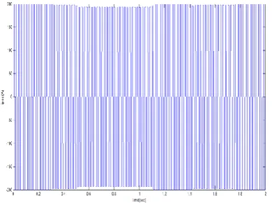
Figure 12: Current at the PCCwith PI controller
[image:7.595.59.254.102.247.2]The current at the point of common coupling with PI controller and fuzzy logic controller as shown in figure 12 and 13 respectively.Here the current rating is considered as 200A.The fuzzy logic controller improves the transient behavior so that the percentage harmonic distortion is reduced.
Figure 13: Current at the PCC with fuzzy logic controller
For this situation, two conceivable method of operation can be watched asforward and switch stream. In the forward stream mode, the accessible DG power is not as much as the required load request.
[image:7.595.57.258.370.494.2]The DG inverter additionally changes its control from voltage to current control mode, however just exchanges dynamic basic current. The execution of APFsh is likewise continuous amid the change period.The responsive and consonant current (ish) produced symphonious piece of and symphonious current remuneration execution amid the invert current stream to the matrix because of the high infiltration of DG.
Figure 14: Voltage and current at the load with UPQC
The load voltage and load current wave frames at the purpose of regular coupling in the discrete mode with PI and fuzzy controller as appeared in figure 5.13 and 5.14 separately it is seen that the bends the voltage and current wave shapes are decreased to better degree with fuzzy rationale controller when contrasted with PI controller.
At the point when the DG power winds up noticeably higher than the required load request, the additional vitality is exchanged to the matrix and capacity and this is named the turn around stream mode. At this stage, the system current winds up plainly out of stage with the voltage at PCC.But by introducing UPQC it doesn't kept up the greatest power quality improvement.With this by utilizing the FUZZY rationale controller an enhanced power quality i.e, voltage at the purpose of normal coupling Vpcc ought to be kept up steady contrasted with incorporation of UPQC.
Under such conditions,which the different execution of UPQCμG−IsDRThas been assessed. The droop pay In unique and bidirectional power stream condition amid a voltage sagIn dynamic and bidirectional power stream condition amid a voltage hang (80%) pay.
[image:7.595.334.537.589.729.2]© 2017, IRJET | Impact Factor value: 5.181 | ISO 9001:2008 Certified Journal
| Page 1398
The execution is acquired with the dynamic difference in idg, which is reflected in the progressions of is. The heap current and the heap voltage by coordination of fuzzy rationale controller. Figure 5.13 shows Voltage and current at the heap with fuzzy controller the voltage list (84% approx.) pay. Combination of fuzzy controller the voltage and current at the heap looked after consistent.
CONCLUSION
This Thesis displayed fuzzy controller based UPQC and its incorporation with the matrix associated μG condition. The outcomes demonstrated that the fuzzy controller can remunerate the voltage and current unsettling influence at the PCC amid the interconnected mode. Execution is likewise seen in bidirectional power stream condition.In islanded mode, the DG converters just supply the activepower. Along these lines, the DG converters don't have to bedisconnected or change their control system to keep the μGoperating in whenever with any condition. Islanding detectionand consistent reconnection procedure by the fuzzy controller and the dynamic change with bidirectional power stream arevalidated in MATLAB for a DG incorporated μG System without trading off on power quality.
SCOPE FOR THE FUTURE WORK
In this theory combination of fuzzy rationale controller is utilized tomaintain the consistent voltage at the purpose of basic coupling for both islanding and interconnected methods of operations of microgrid.In future for better change of remuneration of voltage hang neuro fuzzy rationale controller is utilized.
REFERENCES
[1] S. K. Khadem, M. Basu “UPQC for power quality improvement in DG integrated smart grid network—A review,” Int. J.Emerg. Electr.Power Syst., vol. 13, no. 1, p. 3, 2012.
[2] A. Kahrobaeian and Y.-R. Mohamed, “Interactive distributed generation
interface for flexible micro-grid operation in smart distribution systems,”
IEEE Trans. Sustainable Energy, vol. 3, no. 2, pp. 295– 305, Apr. 2012.
[3] X. Yu, A. M. Khambadkone “Control of parallel-connected power converters for low-voltage microgrid— Part I: A hybrid control architecture,” IEEE Trans. Power Electron., vol. 25, no. 12, pp. 2962–2970, Dec. 2010. [4] T. Jimichi, H. Fujita “Design and experimentation of a dynamic voltage restorer capable of significantly reducing an energy-storage element,” IEEE Trans. Ind. Appl., vol. 44, no. 3, pp. 817–825, May/Jun. 2008.
[5] J. Nielsen, F. Blaabjerg, and N. Mohan, “Control strategies for dynamic voltage restorer compensating
voltage sags with phase jump,” in Proc.16th APEC, vol. 2. 2001, pp. 1267–1273.
[6] H. Kim, T. Yu, and S. Choi, “Indirect current control algorithm for utility
interactive inverters in distributed generation systems,” IEEE Trans. Power Electron., vol. 23, no. 3, pp. 1342– 1347, May 2008.
[7] S. S. Choi, J. D. Li“A generalized voltage compensation strategy for mitigating the impacts of voltage sags/swells,” IEEE Trans. Power Del., vol. 20, no. 3, pp. 2289–2297, Jul. 2005.
[8] M. Moradlou and H. R. Karshenas, “Design strategy for optimum rating
selection of interline DVR,” IEEE Trans. Power Del., vol. 26, no. 1, pp. 242–249, Jan. 2011.