© 2017, IRJET | Impact Factor value: 5.181 | ISO 9001:2008 Certified Journal | Page 1029
Nexus Assembly Automation
Shantanu Sonar
1, Rohan Katariya
2, Abhijeet Koke
3, Shubham Tangade
41,2,3,4
Dept of Mechanical Engineering, DVVP college, Maharashrtra, India
---***---Abstract -
In today’s context Indian Government has launched many projects such as Clean India Projects, Start Up –Stand Up India Mission, Make in India Mission to name a few, In these Missions the role of Science and Department Technology and Innovation (SIT) is unfathomable. We see these developments as opportunities for capacities and skills building. The stress to create indigenous defense industry environment is need of the hour.This paper mainly focus on study of each and every technical aspects and to get technical knowledge by applying various recent trends in engineering. Use of various automation techniques such as Bowl Feeder, Hydraulics & Pneumatics, Indexing Mechanism, Robotics and Sensors. The key results of various techniques is to reduce the cycle time and increase the production rate and also reduce the wastage. Furthermore, in our project by applying trial and error methods we will decide best of the best automated technique to achieve goal.Key Words
:
Bowl Feeder, Pneumatics, Indexing Mechanism, Robotics and Sensors, Automation1. INTRODUCTION
Now a days technology is growing rapidly and in order to make the full fledge of the technical aspects the work included is highly automatic as SPM (Special purpose machine ) is concern. The existing machines operation is done on the manual basis. as it takes the very much time due to that the organization can not be fulfill their requirements as it is most concern able things. so we introduce our machine which is highly automatic and that is through out handling of the components is done without any manual efforts. The nexus is an important part in MCB (so it has to be done on the basis proper working dimension and proper function ability
The main function of the MCB is to brake the circuit when there is interrupted electric supply occurs and there is sudden breakdown of electricity and to work on this we can use the MCB which works as a circuit breaker. and avoid the failure of progressive equipment.
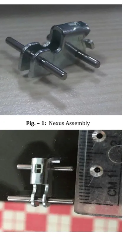
nexus assembly is a mechanical part of MCB(Miniature Circuit Breaker) used for latching purpose. It is made of a one nexus and 2 pins. This assembly is presently done on a machine called as knuckle press which is pneumatically operated by push button.
Loading and Unloading of these three parts and assembly respectively is totally manual with existing output of 6 jobs per minutes.
1.1
Objective
To reduce current cycle time
To increase production rate
To automate machine by considering other special purpose machines
To reduce human efforts.
To get accurate and precise work
To reduce wastage of material man power and time Minimum handling of material
1.2
Problem Statement
Previously, operation are performed as follows: 1. Loading of 2 pins manually in jig. 2. Loading of nexus on fixture manually.
3. Press operation is done by operating push button. 4. Unloading is done by manually.
5. All of the above operations are time consuming. 6. In order to get productivity and increased
production rate, this is our problem statement
1.3 SCOPE
In present days, technology is growing very fast hence to get accurate and precise work in minimum possible time is must. In present era automation plays important role in manufacturing process, hence by doing automation in manufacturing process we can get optimize production.
1.4 Methodology
Use of Bowl feeder
Use of Sensors
Use of pneumatic & hydraulic Automation
Use of Indexing Mechanism
Use of conveyors
Use of robotics
© 2017, IRJET | Impact Factor value: 5.181 | ISO 9001:2008 Certified Journal | Page 1030
[image:2.595.90.302.111.512.2]2. NEXUS ASSEMBLY
Fig. – 1: Nexus Assembly
Fig. -2: Nexus Assembly
3. DESIGN AND SELECTION OF COMPONENTS
Mechanical Parts Used-3.1
Vibratory Bowl Feeder
Fig. -3 Vibratory Bowl Feeder
Vibratory bowl feeders are commonly used for aligning and feeding small parts. A typical vibratory bowl feeder consists of a bowl mounted on a base by three or four inclined leaf springs. The springs constrain the bowl so that, as it travels vertically, it also twists about a vertical axis. As parts move up an inclined track along the edge of the bowl, tooling in the bowl orients parts into the proper orientation or rejects misaligned parts into the center of the bowl where they begin their travel up the track again. An electromagnet, mounted between the base and the bowl, generates the force to drive the bowl feeder. The feeder base rests on rubber feet, which serve to isolate the vibration of the feeder from the surrounding environment. Parts are conveyed in the bowl by one of two modes: sliding or hopping. In the sliding mode, motion is produced from friction between the part and the bowl. As the bowl rises and twists forward, the friction between the track and the part pushes the part forward with the track. When the track descend sand twists backward, the force of friction is smaller and the part slides forward relative to the bowl. In the hopping mode, the part moves forward with the bowl as it rises and twists, but it experiences free fall when the bowl's downward acceleration exceeds the acceleration of gravity. During free-fall, forward motion is created as the bowl moves backward relative to the part.
[image:2.595.340.567.440.702.2]3.2Indexing Plate
© 2017, IRJET | Impact Factor value: 5.181 | ISO 9001:2008 Certified Journal | Page 1031
Fig. -5: Indexing Plate
Indexing mechanism with parallel axes are a form of planar mechanism in which a plate-type driving cam is used to perform transmission between two parallel axes. Of the various indexing mechanisms available (e.g., the Geneva wheel and cylindrical cam), indexing cams with parallel axes are particularly attractive due to their high speed, low noise, low vibration and reliability. Such mechanisms have a low indexing number and a large angular stroke output.one can set indexing mechanism as per requirement such as 2 station, 4 station, 8 station and so on. As a result, they are ideally suited to applications requiring small stop numbers, such as paper cutting machines, jelly can molding machines and packaging and printing machines.
3.3
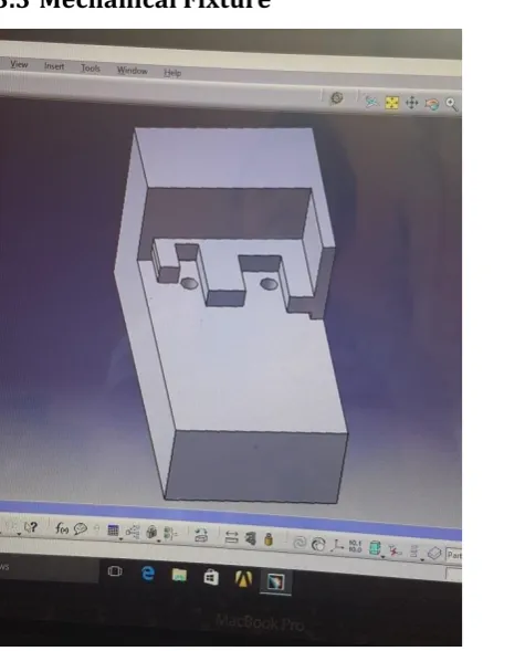
Mechanical Fixture
[image:3.595.73.297.97.251.2]Fig. -6: Mechanical Fixture
Fig. -7 Mechanical Fixture
Mechanical Fixture is one of the important part of design, as these fixture is used for holding the link assembly in proper manner and circumspectly to perform a required work such as feeding a pins (kinematic pin and latch pin), punching operation through pneumatic press, and lastly unloading of final job.
3.4 Pneumatic Knuckle Press
The machine is a press riveting pneumatically operated machine which is operated by push button. Operation is performed by 5/3 dc valve on working pressure of 6 Bar. 600kgf force is required to assembly.
3.5 Gear Mechanism-Worm & Worm Wheel
[image:3.595.57.295.460.755.2] [image:3.595.322.546.579.739.2]© 2017, IRJET | Impact Factor value: 5.181 | ISO 9001:2008 Certified Journal | Page 1032 A worm drive is a gear arrangement in which a worm
(which is a gear in the form of a screw) meshes with a worm gear (which is similar in appearance to a spur gear). The two elements are also called the worm screw and worm wheel. The terminology is often confused by imprecise use of the term worm gear to refer to the worm, the worm gear, or the worm drive as a unit.
Like other gear arrangements, a worm drive can reduce rotational speed or transmit higher torque. A worm is an example of a screw, one of the six simple machines.
A gearbox designed using a worm and worm-wheel is considerably smaller than one made from plain spur gears, and has its drive axes at 90° to each other. With a single start worm, for each 360° turn of the worm, the worm-gear advances only one tooth of the gear. Therefore, regardless of the worm's size (sensible engineering limits notwithstanding), the gear ratio is the "size of the worm gear - to - 1". Given a single start worm, a 20 tooth worm gear reduces the speed by the ratio of 20:1. With spur gears, a gear of 12 teeth must match with a 240 tooth gear to achieve the same 20:1 ratio. Therefore, if the diametrical pitch (DP) of each gear is the same, then, in terms of the physical size of the 240 tooth gear to that of the 20 tooth gear, the worm arrangement is considerably smaller in volume.
3.6
Electrical Parts Used-
[image:4.595.358.506.111.340.2]3.6.1 First generation Robotic Arm
Fig. -9: First generation robotic arm Robotics consist of 3 types mainly 1st 2nd 3rd generation in which 1st generation is used for simple work such as pick and place only while 2nd generation robot is used for pick and place as well as transmitting rotary and translatory motion ,3rd generation robot is called as intelligent robot which sense the object and perform automatic operation.
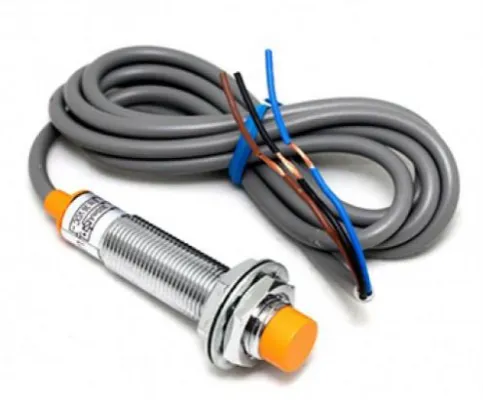
[image:4.595.312.554.384.584.2]3.6.2 Proximity Sensor
[image:4.595.103.242.484.634.2]Fig. -10: Proximity Sensor
Fig. -11: Proximity sensor
© 2017, IRJET | Impact Factor value: 5.181 | ISO 9001:2008 Certified Journal | Page 1033 report a graduated detection distance. Some know these
[image:5.595.313.523.265.523.2]process as "thermosensation". Proximity sensors can have a high reliability and long functional life because of the absence of mechanical parts and lack of physical contact between sensor and the sensed object. Proximity sensors are commonly used on smartphones to detect (and skip) accidental touchscreen taps when held to the ear during a call.[1] They are also used in machine vibration monitoring to measure the variation in distance between a shaft and its support bearing. This is common in large steam turbines, compressors, and motors that use sleeve-type bearings. International Electrotechnical Commission (IEC) 60947-5-2 defines the technical details of proximity sensors.
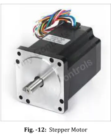
Fig. -12: Stepper Motor
A stepper motor or step motor or stepping motor is a brushless DC electric motor that dividesa full rotation into a number of equal steps. The motor's position can then be commanded tomove and hold at one of these steps without any feedback sensor (an open-loop controller), aslong as the motor is carefully sized to the application in respect to torque and speed
.
4. TIME REDUCTION CALCULATION
Time required on current working machine (Manual Operation) – 15 to 16 second.
Working Station – 8
After automated rotary table Total ideal time – 8 Station *5 second = 40 second
Total time for completing 1 revolution = 48+40 = 88 1 rpm = 1 min. so 1.25rpm = 48 sec.
We have 16 jobs per cycle, For 1 job = 88/16 = 5.5 sec
Hence 5.5 second is our required time.
5. CALCULATION OF TIME AND JOBS
Total time available = 420 minutes in 1 working shift =420*60 sec
=27,000 sec.
Time required per Day- 27000*3 = 81,000 sec.
Time required per Month = 81,000 sec * 25 Working days = 2.025*10^6 sec.
Total jobs = 2.025*10^6 / 5.5 sec per job = 3.5 lakh jobs approx.
Fig. -13: Implementation flow chart
WORKING STATION 1 (LOADING) –
The Loading station is where the nexus is loaded inside the fixture by one arm robot with 3 degrees of freedom. The bowl feeder is placed at 1200 mm height from the floor and mechanical vibrator which works on the principle of electrical vibration is placed between loading station and bowl feeder inclined
The nexus is feeded from bowl feeder and the straight path through the mechanical vibrator towards the loading station, where the one arm robot pick up the nexus and placed into the fixture, where the link is rigidly fixed inside the fixture by the help of nexus lock front which is pull against the force of the spring and the proper fitting is to be done on the loading station.
3.6.3
Stepper Motor
[image:5.595.89.269.288.505.2]© 2017, IRJET | Impact Factor value: 5.181 | ISO 9001:2008 Certified Journal | Page 1034
WORKING STATION 2 (Ideal station) – It is situated to enhance the ergonomics as well as to promote the safety for the user. It also allows to reduced the failure mode.
WORKING STATION 3 (PIN FEEDING) – This station is to putting the pin manually with the help of worker. There are 2 holes provided at the nexus road the 2 pins one is pin and other one is pin are fitted inside the hole manually due to clearance fit between pin and hole during putting of the pin, the worker should take care of proper alignment between 2 pins. Similarly maintain the constant distance between the pins.
WORKING STATION 4 (LASER SENSOR) – This station is used to ensure that the pin is inserted in the hole in proper manner. Sensor senses the whole arrangement is properly aligned or not. If any problem engenders then sensor gives the red signal to an operator.
WORKING STATION 5 (PRESS MACHINE) – The rigid fitting of a pin inside the link is done here. The machine used for the press fit operation is nothing but the knuckle press which is hydraulically operated. The working pressure is about 6 bar and the arrangement ensures that the pin is thoroughly encounters inside the nexus.
WORKING STATION 6 (IDEAL STATION) – It is similar to station no 2, but in future scope we will giving the measurement sensor to the system which measures the position of a nexus and a pin and allows the job is accurately fitted or not.
WORKING STATION 7 (UNLOADING STATION) – At this station job is removed from the fixture by using robotic arm. It is having 3° of freedom, the end part of a robotic arm is the gripper which is actually in contact with the nexus assembly the inner design of the gripper is same as that of the outer part of the nexus in suitable way, robotic arm operated hydraulically.
WORKING STATION 8 (IDEAL STATION) – It is also similar to the station no 2
7. ADVANTAGE
Increase in production rate.
Increase in accuracy.
Less online inspection.
Less involvement of workers.
Total cost of assembly reduced.
Initial cost is high but production rate is high and running cost is low.
8. CONCLUSIONS
To sum up, we had concluded that the automation of machine is the group of different Computer, Electrical, Electronics, Mechanical systems to reduce human effort. Automation of single machine can be done in different stage. Different mechanisms used are Bowl Feeder, Indexing Mechanism, Integrated Sensors, Robots. Factors affecting the selection of this mechanism are spaced available money extend of automation required man power reduction, accuracy required, wastage occurred. By considering these all factors optimum or best solution must be found for automation of Knuckle Press.
REFERENCES
Reference Papers –
1) Bernard J Schroer, Johnson Research Center, Unwerstty of Alabama m Huntswlle, Huntsvtlle, Alabama 35899, USA.
2) A Systems Model and Simulation of the Vibratory Bowl Feeder Gary P. Maul and M. Brian Thomas, The Ohio State University, Columbus, Ohio .
3) Design and analysis of indexing cam mechanism with parallel axes Jung-Fa Hsieh, Department of Mechanical Engineering, Far East University, No. 49, Zhonghua Rd., Xinshi Dist., Tainan City 74448, Taiwan, ROC.
4) Automated heavy load lifting and moving system using pneumatic cushions. E. Lisowski, G. Filo1Cracow University of Technology, al.Jana Pawła II 37, 31-864 Krakόw, Poland.
5) Integrated smart sensorsJohan H HmJsmgDelftUmversll} of Technology, Electrical Engmeermg Faculty, Laboratory for Electromclnstrumentatwn, Mekelweg 4, 2628 CD Delft (Netherland').
Reference Books –
1. Aliciatore&Histand, Introduction to Mechatronics and Measurement system, Mc-Graw Hill Publication, 2011.
2. Machine Design,V.B. Bhandari. 3. Theory of Machine, S.S.Ratan.
BIOGRAPHIES
© 2017, IRJET | Impact Factor value: 5.181 | ISO 9001:2008 Certified Journal | Page 1035 Rohan Rajkumar Katariya
BE(Mechanical) Diploma(Mechanical)
Abhijeet Sharad Koke BE(Mechanical) Diploma(Mechanical)
Shubham Ashok Tangade BE(Mechanical)