© 2018, IRJET | Impact Factor value: 6.171 | ISO 9001:2008 Certified Journal | Page 1895
IOT based Industrial Automation
Sanyuta Swami
1, Priyanka Nalawade
2, Sayali Jadhav
3, Prof N.C .Yadav
41,2,3 Student of Electronics and Telecommunication, Dr.Daulatrao Aher, College of Engineering, Karad
4Assistant Professor of Electronics and Telecommunication Dr.Daulatrao Aher College of Engineering, Karad
---***---Abstract- IOT or internet of things is a technology that makes use of control systems such as computer to control the physical devices over the internet. Here we propose efficient industry automation system that allows user to efficiently control industry appliances/machines over the internet. We use 3 loads as industrial appliances or machines and a motor to demonstrate as an industrial motor.
I. INTRODUCTION:
The AVR family microcontroller is used by our system for processing all user commands. For the connection to the internet and to receive the user commands a Wi-Fi modem is used. WIFI modem receives the commands which are sent through the internet. The received information is decoded by the WiFi modem and passed to the microcontroller. The microcontroller then takes necessary actions as per user’s commands. The state of the system is displayed on the LCD display. Thus the entire industry is automated using online GUI for easy industry automation.
II. OBJECTIVE:
Since today is the generation of smart phones, people prefer smart work. Same goes with the industries. The term automation has led to a great change in the world of industries. Some industries are fully automated while other are partially automated. In short automation has become an important term, whether at home or the industries. Our project focuses on the industrial automation. The machines can be controlled manually from long distance as well.
III.LITERATURE SURVEY:
Geetesh Chaudhari [1] “Industrial Automation using sensing based application”-The system makes use of microcontroller and various sensors to control the industrial devices using Bluetooth.
Ashwini Deshpande [2] “Industrial Automation using Internet of Things”-The industrial devices are controlled using cloud server which alerts the admin about uneven conditions using Bluetooth.
Dr.V.Ramya [3] “Raspberry Pi Based Energy Efficient Industrial Automation System”-Sensors such as gas sensor, temperature sensor are used to detect the faulty conditions. Raspberry Pi is connected through the LAN cable to the server PC in the Control Unit.
III. BLOCK DIAGRAM:
IV.HARDWARE DETAILS:-
1. POWER SUPPLY:-
In this project circuits and motor are used which require +12V & +5V (DC) supply, to fulfill this requirement we have used following circuit of power supply which provides regulated +12V & +5V.(DC)
WORKING:
Four diodes (IN4007) are connected to secondary of transformer in bridge for rectifying AC into DC. Capacitor 1000 f & 1f are used as a filter red led shows that rectification and filtering is ok.
© 2018, IRJET | Impact Factor value: 6.171 | ISO 9001:2008 Certified Journal | Page 1896 2. ARDUINO UNO:-
A microcontroller board on which the Arduino Uno is based is ATmega328P. The microcontroller has 14 digital input/output pins of which 6 can be used as PWM outputs, 6 analog inputs, a 16 MHz quartz crystal, a USB connection, a power jack, an ICSP header and a reset button. ATmega328P contains everything needed to support the microcontroller. It is connected to computer using a USB cable or given a power supply with AC-to-DC adapter. In case of any severe damage, it can be replaced with a new chip.
The meaning of word "Uno" is one in Italian and was chosen to mark the release of Arduino Software (IDE) 1.0.The reference versions of Arduino were the Uno board and version 1.0 of Arduino Software (IDE). The Uno board is the reference model and first in the series of USB Arduino boards, for an extensive list of current, past or outdated boards.
Technical specs
Microcontroller :ATmega328P
Digital I/O Pins :14 (of which 6 provide PWM output)
PWM Digital I/O Pins : 6
Analog Input Pins : 6
Operating Voltage : 5V
Input Voltage : 7-12V
Input Voltage (limit) : 6-20V
Flash Memory : 32KB (of which 0.5 KB used by boot loader
SRAM : 2 KB (ATmega328P)
EEPROM : 1 KB (ATmega328P)
DC Current per I/O Pin: 20 mA
DC Current for 3.3V Pin: 50 mA
Clock Speed : 16 MHz
3. Wi-Fi MODULE:
This is reliable and ultra-low cost module that is based on ESP8266 chipset and easy to use. It is used along with a microcontroller that configures and communicates through AT commands.
The embedded Wi-Fi solutions were a bit pricey to implement for hobbyist. This WiFi module has wide working range and many applications.
APPLICATIONS:
Internet of Things (IoT)e.g. home automation
Wireless Remote Control
Smart plug and lights
Wireless Sensor Networks
IP cameras
Wireless UART
FEATURES:
Built in Client-Server Mode
Integrated 10 bit ADC
400 Meters Working Distance
Integrated TCP/IP protocol stack
On Board 2.4Ghz Ceramic Antenna
IPX Connector for optional external antenna
© 2018, IRJET | Impact Factor value: 6.171 | ISO 9001:2008 Certified Journal | Page 1897 The amazing community support provides all the
information for ESP8266.
Note: The ESP8266 Module is not capable of 5-3V logic shifting and will require an external Logic Level Converter. Please do not power it directly from your 5V dev. board.
4. RELAY DRIVER IC ULN 2803:
The four relays on the board are driven by ULN2803 IC. The operating voltage is 12V but the input signal can be given from microcontroller output working at 3V or 5V to control relays. High current loads working at 110V or 220V AC mains like lights, fans, motors are switched by relays. The status of relay is indicated by individual LEDs.
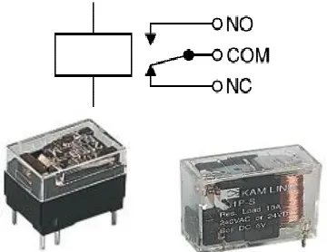
5. RELAY:
A relay is an electrically operated switch. Electromagnet to operate a switching mechanism mechanically or other operating principles are also used by the relays. Relays are used where a circuit is to be controlled by a low-power signal (with complete electrical isolation between control and controlled circuits).
[image:3.612.42.222.371.510.2]
The operating principle is: A magnetic field is created by the current flowing through the coil which attracts a lever and changes the switch contacts. The coil current can be on or off so relays have two switch positions and most have double throw (changeover) switch contacts as shown in the diagram.
Fig Relay showing coil and switch contacts
The circuit diagram shows that relays allow one circuit to switch a second circuit which can be completely separate from the first. For example a low voltage battery circuit can use a relay to switch a 230V AC mains circuit. An electrical connection does not exist inside the relay between the two circuits; the link is magnetic and mechanical.
Current of typically 30mA is passed by a 12V relay, but it can be as much as 100mA for relays designed to operate from lower voltages. Amplification of the small IC current to the larger value is done by using a transistor.
Relays are usually SPDT or DPDT. They can have many more sets of switch contacts, for example relays with 4 sets of changeover contacts are readily available. The relays are designed for PCB mounting but wires can be soldered directly to the pins providing taking care to avoid melting the plastic case of the relay.
The switch connections of the relays are labeled as COM, NC and NO:
COM = Common, always connect to this; which is the moving part of the switch.
NC = Normally Closed, COM is connected to this when the relay coil is off.
NO = Normally Open, COM is connected to this when the relay coil is on.
APPLICATIONS OF RELAY:
In some types of modems or audio amplifiers relays are used to control high voltage circuit.
To Control a high-current circuit with a low-current signal, as in the starter solenoid of an automobile.
© 2018, IRJET | Impact Factor value: 6.171 | ISO 9001:2008 Certified Journal | Page 1898
Time delay functions. Delay opening or delay closing a set of contacts can be done with the relays.
A copper disk between the armature and moving blade assembly may be used by very short delay. Current flowing in the disk maintains magnetic field for a short time, lengthening release time. A dashpot is used for a slightly longer delay. Fluid is filled in the dashpot which is a piston. The time period can be varied by increasing or decreasing the flow rate. For longer time periods, a mechanical clockwork timer is installed.
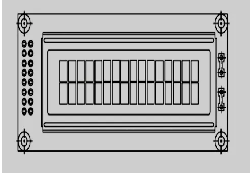
6. LCD DISPLAY:
[image:4.612.38.286.316.486.2]There are various display devices such as seven segment display, LCD display, etc. that can be interfaced with microcontroller to read the output directly. In our project we use a two line LCD display with 16 characters each.
Fig: LCD Display
FEATURES:
o 16X2 dots with cursor
o Built-in controller (KS 0066 or Equivalent)
o + 5V power supply
o 1/16 duty cycle
o B/L to be driven by pin 1, pin 2 or pin 15, pin 16 or A.K (LED)
o RS232 compatible serial interface (2400 & 9600 baud selectable)
o Externally selectable serial polarities (Inverted & Non-Inverted)
o Serially controllable contrast and backlight levels
o 8 user programmable custom characters
o 16 Byte serial receive buffer
V. PROCEDURE FOR EXECUTION:
1. Initialize ESP8266 WiFi module.
2. Enter IP address in the browser and press enter. You can find the IP address using the IP address scanner or Fing application on your android mobile phone.
3. Wait for the web page to open. It will look something like this.
4. Press ON button to start any device.
5. Using port forwarding method, the concept of IOT will be implemented.
VI.CONCLUSION:
The goal of the project was to design a system, which should be easy to implement, and short ranged. The project is implemented through onboard Wi-Fi, which is inbuilt in the mobile phones having an Android as its system.
ACKNOWLEDGEMENT
We are using this opportunity to express our gratitude to everyone who supported us for writing this review paper. We are sincerely grateful to Prof. Yadav.N.C for guiding us on a number of issues regarding this paper.
REFERENCES
© 2018, IRJET | Impact Factor value: 6.171 | ISO 9001:2008 Certified Journal | Page 1899 [2]Ashwini Deshpande, Prajakta Pitale, Sangita Sanap”,
“Industrial Automation using Internet of Things(IOT)”, IJARCET, Volume 5, Issue 2, February 2016.
[3]Dr.V.Ramya, G.Thirumalai Rajan, “Raspberry Pi Based Energy Efficient Industrial Automation System”, IJIRCSE, Volume 2, Issue 1, January 2016.
[4]Rajeev Piyare and Seong Rolee, “Smart Home control and Monitoring System using Smart phone”, ICCA 2013,ASTL volume 24, pp.83-86,2013.
[5]Ayman Sleman and Reinhard Moeller, “Integration of Wireless Sensor Network Service into other Home and Industrial Networks”, IEEE paper.
[6]Cheahwai Zhao, Son Chee Loon, “Exploring IOT applications using Raspberry Pi”, International Journal of Computer Networks and Applications”, Volume 2, Issue 1, February 2015.
[7]R.A.Ramlee, M.A.Othman, M.H.Leong, M.M.Ismail, “Smart Home System Using Android Application, ICoICT, (IEEE), March 2013.
[8]Prof.R.S.Suryanashi, Kunal Khivensra, Gulam Hussain, Nitish Bansal, “Home Automation System using Android and WiFi”,IJECS, Voulme 3, Issue 10, October 2014.