© 2018, IRJET | Impact Factor value: 6.171 | ISO 9001:2008 Certified Journal | Page 2675
Design of an FPGA based Control System for Robot
Uzma Shaikh
1, Shraddha Bawangade
2, Ahmadi Tahseen
3, Saniya Anjum
4, Prof. M. Nasiruddin
51,2,3,4 B.E Student, Department of Electronics and Telecommunication Engineering, ACET, Sadar, Nagpur, India 5Associate Professor & HOD, Electronics and Telecommunication Engineering, ACET, Sadar, Nagpur, India
---***---Abstract -
Robots save workers from performing dangerous tasks. They can work in hazardous condition, that human just can’t do. Robots main position in society is to assist humans by taking on the jobs that are dirty, dull or dangerous. As the work done in the field of robotics make robots technologically more advanced, they learn how to do jobs faster and better than humans. A robot that avoid obstacles and allows knowing the distance from such obstacles was built. The work done on this robot till date consists of two ultrasound transducers placed in the front and the back of the system, and the infrared ones placed on the sides. The basic configuration gives autonomy to the robot, allowing the obstacles evasion and avoiding the collision with objects around to generate possible escape routes. The FPGA (Field Programmable Gate Array) was used in the basic structure to receives the digitized values from the sensors, which formats the data and performs operations that will throw as results the control signals that will indicate to each motor the movement they must follow to avoid an obstacle according to the measured distance. The idea of this paper is to modify the basic configuration by using Verilog HDL language to implement combining FPGA chip with ultrasonic ranging module and control motor driver to achieve automatic obstacle avoidance function. And this is done by adding more transducer to the previous system in order to enhance the application of the system, by introducing light intensity, sound detection, depth detection, temperature and fire sensing module. This development has changed the dynamics of robotics and brought them into the workplace, making them pivotal to a business.Key Words: Obstacle Avoidance Function, FPGA(Field Programmable Gate Array), Transducers, Sensors, Verilog HDL, Ultrasonic Ranging.
1. INTRODUCTION
Robots increase worker safety by preventing accidents since humans are not performing risky jobs. They produce more accurate and high quality of work, without making any mistake and are more precise than human workers. Robots are configured to perform different type of task which involve the movement and orientation of the robots. This paper uses ultrasonic ranging module which is widely applied in industry, agriculture, transportation, environment, safety protection, the energy measurement and other scientific fields. The performance indexes of ultrasonic ranging such as measuring precision, measuring distance and measuring reliability and so on, has a very important role to improve the control precision and
reliability of the related application system, enhance production efficiency, and promote the development of science and technology the ultrasonic obstacle which is responsible for receiving the echo, and producing drive signals, and then controlling the robot to avoid obstacle. FPGA has many features such as perfect efficiency, portable, easy to operate, good secrecy performance, subtle real-time performance, high integration [3].
This system adopts FPGA as the main control chip which controls the motor driver through the real-time distance measured by ultrasonic module, and then leads the robot to avoid obstacle intelligently. This design employs the L293D motor driver module which makes the circuit work stable duo to its high stability. A robot with number of sensors and numbers of motors could be controlled concurrently with use of a single FPGA chip. So that, this is a small attempt to implement a mobile robot which avoids obstacles with use of range sensors and wheeled motors. The mobile robot platform can move forward, backward, turn right & left. With use of the four range sensors the robot avoids obstacles. This obstacle avoidance system can be implemented in medical assertive devices, industrial robots and outdoor / indoor navigation robots.
2. METHODOLOGY
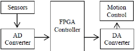
[image:1.595.320.550.597.683.2]In previous work a robot capable of locomotion carries an FPGA board in charge of signal processing and control signal generation. Sensors send information to an analog to digital converter and this information passes to the FPGA, when a control signal is generated, the information goes to a digital to analog converter that finally sends orders to the system motors according to Figure 1.
Figure 1: Basic Block Diagram of the System
© 2018, IRJET | Impact Factor value: 6.171 | ISO 9001:2008 Certified Journal | Page 2676 to the system motor according to the figure 2.
Figure 2: System Overview
The FPGA Development board used in this project is ALTERA Cyclone II EP2C5T144 chip. This board can easily be embedded into user’s application. Applications include from simple logic control, data acquisition, signal processing, to mathematical calculation functions. It consist of 4068 logic elements, multiple 4k RAM blocks giving a total of 119898 bits, 13 multipliers with 2 PLLs and 89 I/Os. Maximum clock frequency is 300 Mhz and it operates on 5V DC single power.
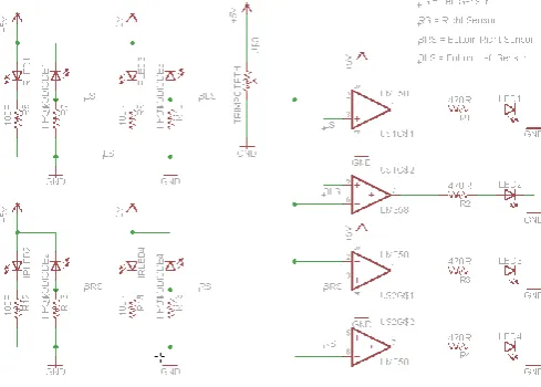
[image:2.595.311.556.178.353.2]An infrared sensor circuit is one of the basic and popular sensor modules in an electronic device. This sensor is analogous to human’s visionary senses, which can be used to detect obstacles and it is one of the common applications in real time. This circuit comprises of the following components LM358 IC, two IR transmitter and receiver pair, resistors of the range of kilo ohms, variable resistors and LED (Light Emitting Diode). In this project, the transmitter section includes an IR sensor, which transmits continuous IR rays to be received by an IR receiver module. An IR output terminal of the receiver varies depending upon its receiving of IR rays. Since this variation cannot be analyzed as such, therefore this output can be fed to a comparator circuit. Here an operational amplifier (op-amp) of LM358 is used as comparator circuit. When the IR receiver does not receive a signal, the potential at the inverting input goes higher than that on non-inverting input of the comparator IC(LM358). Thus the output of the comparator goes low, but the LED does not glow. When the IR receiver module receives signal, the potential at the inverting input goes low. Thus the output
Figure 3: IR Sensor Circuit
Ultrasonic ranging module used is HC-SR04 which provides 2cm to 400cm non-contact measurement function, the ranging accuracy can reach to 3mm. The modules includes ultrasonic transmitters, receiver and control circuit. The basic principle of work, using IO trigger for at least 10us high level signal, the module automatically sends eight 40kHz and detect whether there is a pulse signal back, if the signal back, through high level, time of high output IO duration is the time from sending ultrasonic to returning. The SRF05 output is a 5 volts signal with a variable period that depends on the distance from the robot to the obstacle, this signal is treated to obtain a voltage value that is proportional to the distance to the object location. The figure 4 shows the sensor and its emission pattern.
[image:2.595.43.282.235.397.2]Test distance = (high level time*velocity of sound (340m/s) / 2.
© 2018, IRJET | Impact Factor value: 6.171 | ISO 9001:2008 Certified Journal | Page 2677 Figure 5: Ultrasonic Sensor Operation at Different
Condition
Automatic dark detector module senses darkness. As the light level decreases and LDR(Light Dependent Resistor) meets the maximum threshold resistance, the circuit automatically switches on the LED D1 as shown in the figure 8. A dark detector can be made using a variable resistor. The sensitivity of the circuit can be adjusted with a variable resistor. If
High resistance-> more darkness to switch on the LED. Low resistance-> less darkness to switch on the LED.
Figure 6: Light detector sensor
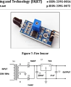
The fire sensor (flame sensor) is used to detect the presence of fire or other infrared source. Flame or a light source of a wavelength in the range of 760nm to 1100nm can be detected. The features of fire sensor are that it can be used in fire fighting robot or heat seeking robot. It is small and compact in size with adjustable threshold value and 2 state binary outputs (logic high and low). It comparatively has easy mounting with a screw hole. It basically operates at 5v power supply. The module has simple 3pin male berg connector having Vcc, ground and output pin. The potentiometer is provided to adjust the threshold level.
[image:3.595.39.289.90.228.2]Figure 7: Fire Sensor
Figure 8: 5v power supply circuit using 7805 voltage regulator.
Figure 9: Power supply layout diagram.
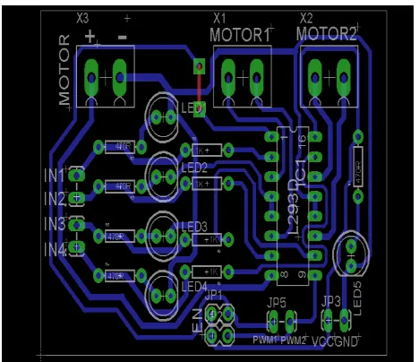
[image:3.595.310.556.385.517.2] [image:3.595.83.277.397.586.2]© 2018, IRJET | Impact Factor value: 6.171 | ISO 9001:2008 Certified Journal | Page 2678 Figure 10: Motor Driver Circuit Diagram
Figure 11: Motor Driver Layout Diagram
Principle of working of robot is to find the available and possible way to go ahead. Robot find its way on the basis of sensor data. Sensor interact with environment and generate signal. The Signal from sensor is given to comparator, comparator compare the signal with threshold value and generate output. If signal is less than threshold then output will be logic ‘0’ and if signal is greater than threshold then output will be logic ‘1’. Whenever the oBackSensortacle is found comparator generate the output logic ‘1’ and for no oBackSensortacle logic ‘0’ will be generate. The output of comparator is given to the input of FPGA kit on respective pins. Then FPGA kit takes the decision based on available sensor data, conditions in Verilog code given in next points.
[image:4.595.45.279.292.494.2]Like above in Verilog, the robot take decision as per condition. Then after FPGA kit generate data for motor driver controller(L293D) to drive a motor.
Figure 12: Block diagram of proposed structure
3. CONCLUSIONS
With the advancement in the field of robotics, robots can be used in hazardous condition where the presence of human is unsafe. The key point in this system is to propose the solution to the problem of determining and calculating distances and the obstacles in the way, and thereby connecting extra module to the basic structure in order for obstacle avoidance which enhance the application of the project. The system has used ultrasonic raging module with various sensors that can be drived using motor, that lead to increase in productibility and accuracy of system.
[image:4.595.310.559.485.741.2]© 2018, IRJET | Impact Factor value: 6.171 | ISO 9001:2008 Certified Journal | Page 2679 Figure 14: Synthesis results (RTL Gate view)
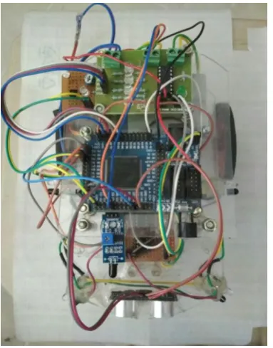
Figure 15: Hardware structure of project
The table shown below gives the detail description of movement of robot.
FS: Front Sensor BS: Back Sensor LS: Left Sensor RS: Right Sensor BL: Back left sensor BR: Back Right sensor FrS: Fire Sensor
Sr
No FS BS LS RS BL BR FrS Robot Movement
1 0 0 1 1 0 0 1 Forward
2 0 0 1 0 0 0 1 Forward
3 0 0 0 1 0 0 1 Forward
4 1 0 1 0 0 0 1 Right
5 1 0 0 0 1 0 1 Right
6 0 0 0 0 1 0 1 Right
7 0 0 1 0 1 0 1 Right
8 1 0 0 1 0 0 1 Left
9 0 0 0 1 0 1 1 Left
10 1 0 0 1 0 1 1 Left
11 1 0 1 0 1 0 1 Right
12 0 0 0 0 0 1 1 Left
13 1 0 0 0 1 0 1 Right
14 1 0 0 0 0 1 1 Left
15 0 0 1 1 1 0 1 Right
16 0 0 1 1 0 1 1 Left
17 0 0 1 0 0 1 1 Left
18 0 0 0 1 1 0 1 Right
19 1 0 1 0 1 1 1 Right
20 1 0 0 1 1 1 1 Left
21 1 1 1 1 1 1 1 Buzzer
22 1 0 1 1 1 1 1 Buzzer
23 0 0 1 1 0 0 0 Forward
24 0 0 1 0 0 0 0 Forward
25 0 0 0 1 0 0 0 Forward
26 1 0 1 0 0 0 0 Right
27 1 0 0 0 1 0 0 Right
28 0 0 0 0 1 0 0 Right
29 0 0 1 0 1 0 0 Right
30 1 0 0 1 0 0 0 Left
31 0 0 0 1 0 1 0 Left
32 1 0 0 1 0 1 0 Left
33 1 0 1 0 1 0 0 Right
34 0 0 0 0 0 1 0 Left
35 1 0 0 0 1 0 0 Right
36 1 0 0 0 0 1 0 left
37 0 0 1 1 1 0 0 Right
38 0 0 1 1 0 1 0 Left
39 0 0 0 1 1 0 0 Right
40 0 0 1 0 0 1 0 Left
41 1 0 1 0 1 1 0 Right
42 1 0 0 1 1 1 0 Left
REFERENCES
[1]Uzma Zabeen Shaikh, Shraddha Bawangade, Ahmadi Tahseen, Saniya Anjum, “Review on Design of a Control System for Robots using FPGA”, 2017 International Journal of Innovative Research in Science, Engineering and Technology (IJIRSET)
[image:5.595.67.259.269.514.2]© 2018, IRJET | Impact Factor value: 6.171 | ISO 9001:2008 Certified Journal | Page 2680 [5]Yoshihiro Niitsu, Saki Itoh, Shinya Kitahara, Hiroya
Minami and Michio Shimomura, “Walking Support by Dangerous Obstacles Notification Using an Electronic White Cane”, 978-1-4673-4728-0/12/$31.00 ©2012 IEEE
[6]R. P. Mahapatra , K. Vimal Kumar , Gaurav Khurana and Roopam Mahajan , “ULTRA SONIC SENSOR BASED BLIND SPOT ACCIDENT PREVENTION SYSTEM”, 2008 International Conference on Advanced Computer Theory and Engineering.
[7Yoshihiro Niitsu, Toshiki Taniguchi and Kouichiro Kawashima, “Detection and notification of dangerous obstacles and places for visually impaired person using a smart cane”, 2014 seventh international conference on mobile computing and ubiquitous networking (ICMU) [8]Kuniaki Kairabata Naruhiro Nishioka Po Chih Lin Hideo Nakamura Hisato Kobayashi, “Distance Mesurement Method under Multiple Ultra Sonic Sensors Environment”, 0-7803-2775-6196 $4.00 0 1996 IEEE
[9]Jun Yang, Chen Zhong, Feng Zhang, Hong Liu, “The Design and Implementation of FPGA-Based Ultrasonic Obstacle Avoidance Car, International Conference on Chemical, Material and Food Engineering” (CMFE-2015)
[10]Gregorio Trinidad Garcia1, Griselda Saldaña-González, Jose Italo Cortes, Carmen N. López Marin, Mariano Larios G, F. Villafuerte-Herrera, “CONTROLLED SYSTEM FOR DISTANCE SENSING USING FPGA”, 1st international conference on instrumentation applied science
BIOGRAPHIES
B.E Student, Department of Electronics and Telecommunication Engineering,
ACET, Sadar, Nagpur, India
B.E Student, Department of Electronics and Telecommunication Engineering, ACET, Sadar, Nagpur, India