Angle Measuring Instrument using Micrometers
R. Saravana
Graduate
Department of Mechanical Engineering
NSCET-Theni, Tamilnadu, India
Abstract— The given name of the new angle measuring instrument is Tanmeter. An instrument for angle measurement based on micrometers readings has been designed. It has the advantage of simplicity, and consequently provides easy operation and an inexpensive instrument. Measurement technique is based on two micrometer readings. That micrometers used to measure the object specific height and length. That readings applied to Tangent formula then find the angle of objects.
Key words: Angle Measuring Instrument, Tanmeter, Taper Angle
I. INTRODUCTION
Tanmeter is an instrument, it is used to measure the taper angle of the objects. A large scale industries used several methods to measure the angle of object like as CMM, Sine bar, Profile projector. But small scale industries not possible to buy a kind of machines. Because its price range and working time is very high.But this measuring instrument exited the kind of problems. Even not to need skilled employee, unskilled employee easy to operate this instrument. One of the major advantage of this measuring instrument is fully worked on manually.
II. EXISTING MEASURING INSTRUMENT
Already the several angle measuring instruments available in the industries. But the manual measuring methods are very few in market. Mostly sine bar used to manually for measure the angle objects.
A. Sine Bar
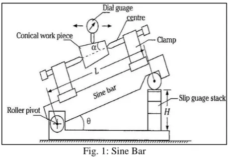
A sine bar consists of a hardened, precision ground body with two precision ground cylinders fixed at the ends. The distance between the centers of the cylinders is precisely controlled, and the top of the bar is parallel to a line through the centers of the two rollers. The dimension between the two rollers is chosen to be a whole number (for ease of later calculations) and forms the hypotenuse of a triangle when in use.
When a sine bar is placed on a level surface the top edge will be parallel to that surface. If one roller is raised by a known distance, usually using gauge blocks, then the top edge of the bar will be tilted by the same amount forming an angle that may be calculated by the application of the sine rule. Sine bar fully worked on manually.
The hypotenuse is a constant dimension—(100 mm or 10 inches in the examples shown).
[image:1.595.313.543.138.296.2] The height is obtained from the dimension between the bottom of one roller and the table's surface.
Fig. 1: Sine Bar
B. Problem Identification of Sine Centre 1) High cost of measuring instrument. 2) Operation time is high.
3) Working principle is difficult.
4) Cannot measure the angle more than 45 degrees. 5) Source of errors in sine centre
a) Error in distance between roller centers. b) Error in slip gauge combination. c) Error in checking of parallelism.
d) Error in parallelism of roller axes with each other.
C. Solution of the Problem 1) Instrument price is reduced.
2) The problem of measuring time is reduced. 3) Easy manual working method.
4) Accuracy is increased.
5) Angle measuring limit 0 to 70 degrees.
III. BLOCK DIAGRAM OF TANMETER
5) Supporting Leg 6) Primary Carriage 7) Carriage Locking Screw 8) Secondary Carriage 9) Tertiary Carriage 10) Secondary Micrometer 11) 11. Primary Micrometer 12) 12. Carriage Locking Screw
Fig. 2: Tanmeter Block Diagram
IV. DESCRIPTION OF IMPORTANT PARTS
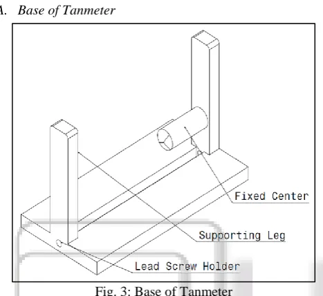
[image:2.595.308.550.67.228.2]A. Base of Tanmeter
Fig. 3: Base of Tanmeter
The tanmeter Bottom base is made of hardened, corrosion-resistant stainless steel with a satin chrome finish that helps reduce glare. That bottom surface has one flat guide way or linear guide way. It’s used to guide the movable center too linearly. The supporting leg is used to guide the primary carriage too vertically.
[image:2.595.48.282.199.413.2]B. Movable Center
Fig. 4: Movable Center of Tanmeter
Movable center is used to hold the conical male objects at various dimension. That threaded hole used to allow the lead screw inside the movable center. That lead screw moves the movable center too horizontally.
C. Primary carriage
Fig. 5: Primary Carriage of Tanmeter
Primary carriage moves vertically to the workpiece. That lead hole moves over the supporting legs. The locking screw used to lock the primary carriage in stationary position. Primary carriage has a one flat guide way. It’s used to guide the secondary carriage.
[image:2.595.308.546.306.449.2]D. Secondary Carriage
Fig. 6: Secondary Carriage of Tanmeter
Secondary carriage moving over the primary carriage. The locking screw used to lock the primary carriage in stationary position. Secondary carriage has a one flat guide way. It’s used to guide the tertiary carriage too horizontally.
[image:2.595.46.257.491.629.2]E. Tertiary Carriage
Fig. 7: Tertiary Carriage of Tanmeter
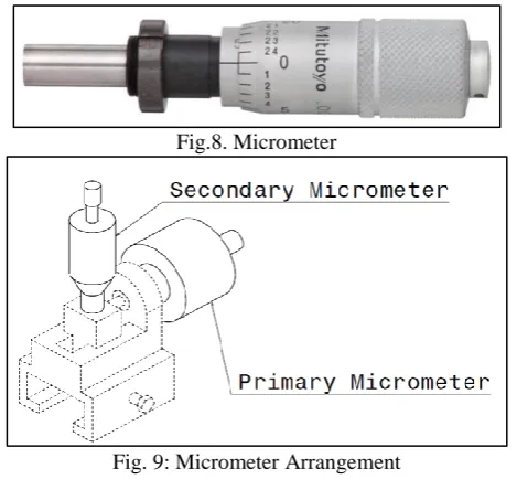
[image:2.595.308.540.504.628.2]Fig.8. Micrometer
Fig. 9: Micrometer Arrangement
The primary micrometer is fitted in secondary carriage. The primary micrometer is used to pull and push the tertiary carriage. Secondary micrometer spindle is direct contact to measure the readings of the conical object.
V. WORKING PROCEDURE OF TANMETER
A. Angle Measuring Method of Conical Male Object
[image:3.595.311.547.68.236.2]1) Fit the Conical Male Object in Tanmeter by the use of Fixed & Movable Centers.
Fig. 10: Workpiece Catching Method
2) To move the primary, secondary and tertiary carriages near to the conical object (or) workpiece by adjust the locking screw and primary micrometer.
Fig. 11: Tanmeter Initial Arrangement
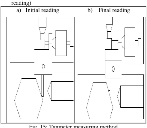
3) Rotate the secondary micrometer thimble after the initial carriage arrangement. That secondary micrometer spindle touch the workpiece. Note the initial readings of primary micrometer and secondary micrometers. It is denoted by PM1 and SM1. (PM1 = Primary Micrometer Initial Reading, SM1 = Secondary Micrometer Initial reading)
[image:3.595.291.550.317.526.2]a) Initial reading b) Final reading
Fig. 12: Tanmeter Measuring Method
4) Next rotate the primary micrometer thimble after the measured the initial readings. That primary micrometer spindle directly attached to the tertiary carriage, so that spindle rotation moves the tertiary carriage to another position. Now rotate the secondary micrometer thimble. That secondary micrometer spindle touch the workpiece another time. Note the final readings of primary micrometer and secondary micrometers. It is denoted by PM2 and SM2. (PM2 = Primary Micrometer Final Reading, SM2 = Secondary Micrometer Final reading) 5) The readings are tabulated and calculated.
B. Angle Measuring Method of Block Object
[image:3.595.45.290.352.609.2]Fig. 13: Workpiece Placing Method
2) To move the primary, secondary and tertiary carriages near to the conical object (or) workpiece by adjust the locking screw and primary micrometer.
Fig. 14: Tanmeter Initial Arrangement
3) Rotate the secondary micrometer thimble after the initial carriage arrangement. That secondary micrometer spindle touch the workpiece. Note the initial readings of primary micrometer and secondary micrometers. It is denoted by PM1 and SM1. (PM1 = Primary Micrometer Initial Reading, SM1 = Secondary Micrometer Initial reading)
a) Initial reading b) Final reading
spindle rotation moves the tertiary carriage to another position. Now rotate the secondary micrometer thimble. That secondary micrometer spindle touch the workpiece another time. Note the final readings of primary micrometer and secondary micrometers. It is denoted by PM2 and SM2. (PM2 = Primary Micrometer Final Reading, SM2 = Secondary Micrometer Final reading) 5) The readings are tabulated and calculated.
VI. CALCULATION
MSR (mm)
VSD (mm)
VSR (div)
T (mm)
DIF (mm)
PM (mm)
PM1
PM2
SM (mm)
SM1
[image:4.595.307.553.158.573.2]SM2
Table 1: Find the Primary & Secondary Micrometer Readings
PM Primary Micrometer SM Secondary Micrometer
PM1 Primary Micrometer Initial Reading PM2 Primary Micrometer Final Reading SM1 Secondary Micrometer Initial Reading SM2 Secondary Micrometer Final Reading MSR Main Scale Readings in mm
VSD Vernier Scale Division VSR Vernier Scale Reading in mm T Total Reading in mm
DIF Difference of Initial and Final readings
VSR = (VSD × LC) in mm (1.1) LC Least Count of Micrometer in mm
Total Reading = (MSR + VSR) in mm (1.2) Difference = (Initial Readings ~ Final Readings) (1.3) PM = (PM1 ~ PM2) in mm (1.4) SM = (SM1 ~ SM2) in mm (1.5) After the tabulation we get the two accurate micrometer readings. One is primary micrometer reading and another micrometer one is secondary micrometer reading. That two readings are consider as adjacent and opposite sides of the triangle. Now that readings are apply the given tangent formula. Finally we get the angle of the conical male object.
The tangent of the angle = length of the opposite side length of the adjacent side
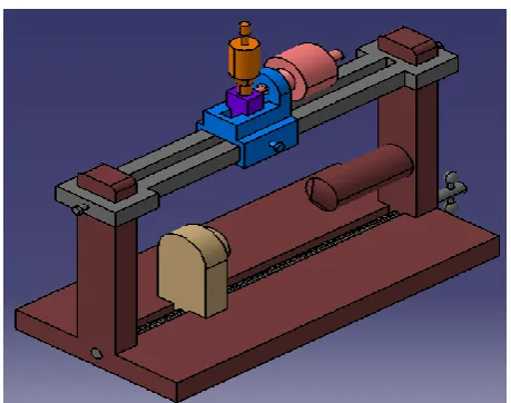
[image:4.595.44.290.513.727.2]VII. THREE DIMENSION MODEL PHOTOGRAPH
Fig. 16: 3D Model of Tanmeter
A. Advantages
High degree of accuracy.
Simple in construction.
Easy to measure the angle.
Low cost of instrument.
Fully worked on manually.
B. Disadvantage
Not measure the conical female objects
VIII. CONCLUSION OF PAPER
Now a days large scale industries are using a coordinate measuring machine to measure the angle of conical male objects. But it’s fully worked on electric power and small scale industries not possible to buy an expensive machines. Available manual measuring machine are few in the market like as sine centre method. But its working procedure is very difficult, number of the components and cost also high. Tanmeter introduced by the solution of that kind of problems.
REFERENCES
[1] Encyclopedia Americana (1988) "Micrometer" Encyclopedia Americana 19: 500ISBN 0-7172-0119-8. [2] "What is a Micrometer & How it historically develops?"
SG Micrometer.
[3] "Whitworth's workshop micrometer", The Practical Mechanic and Engineer's magazine, Nov 1844, pp43-44. [4] Loo Kang, Wee; Hwee Tiang, Ning (2014), "Vernier caliper and micrometer computer models using Easy Java Simulation and its pedagogical design feature-ideas to augment learning with real instruments", Physics Education, 49 (5), arXiv:1408.3803 ,doi:10.1088/0031-9120/49/5/493.
[5] BS EN ISO 3650: "Geometrical product specifications (GPS). Length standards. Gauge blocks" (1999)