The Effect of Drill Point Geometry and Drilling Technique on Tool Life when
Drilling Titanium Alloy, Ti-6Al-4V
F.R. Wong1,* , S. Sharif2, K. Kamdani1, E.A. Rahim1
1
Faculty of Mechanical and Manufacturing Engineering Universiti Tun Hussein Onn Malaysia (UTHM)
Parit Raja, Batu Pahat, 86400 Johor, Malaysia email:[email protected]
2
Faculty of Mechanical Engineering, Universiti Teknologi Malaysia, 81310 Skudai, Johor, Malaysia
email:[email protected]
Abstract:
An experimental investigation was conducted to determine the effect of drill point geometry and drilling methods on tool life and tool wear in drilling titanium alloy, Ti-6Al-4V. Uncoated carbide drills with different type of geometry under various cutting speeds and drilling methods were used in the investigation. Experimental results revealed that both the drill geometry and drilling techniques affect the tool wear and tool life performance when drilling Ti-6Al-4V. It was also found that peck drilling outperformed direct drilling in terms of tool life all cutting speeds investigated. Non uniform wear and chipping were the dominant failure mode of the tools tested under most conditions.
Keywords: Titanium alloy, Peck drilling, Uncoated carbide, Drill point geometry
1. Introduction
Extensive use of titanium and its alloys had been recorded in various applications such as in aerospace industry, automotives, sport equipments, automotives, biomedical, petroleum industry and marine
applications [1]. The utilization has
progressed rapidly due to the attractive characteristics of the materials which include high strength to weight ratio at elevated temperatures, corrosive resistance, fracture resistance characteristics, longer service life and compatibility to composite structures [2,3]. However, machinability of titanium and its alloys can be considered poor due to its high chemical reactivity on tool materials, high temperature strength and low modulus of elasticity [4,5].
Drilling has been an essential technique in aerospace industry and is widely used to produce holes with high quality at low cost and short processing time [6]. For the few decades, many researchers have studied the machinability of titanium alloys especially in turning [7-12] and milling [13-17] operations. Meanwhile, reports on drilling of titanium and its alloys are still limited [2, 18-21].
under various cutting strategies which
include intermittent deceleration feed
drilling, the use of high pressure coolant and vibratory drilling. They reported that intermittent deceleration feed drilling recorded the lowest tool wear hence improved the tool life. Detailed experimental work using Ti-6Al-4V and Ti-48Al-2Mn-2Nb had been carried out by Mantle et al. [19]. They found that the thrust force and torque when drilling Ti-6Al-4V was lower than when drilling Ti-48Al-2Mn-2Nb. Arai and Ogawa [20] suggested that the application of high pressure coolant could extend the tool life when drilling of Ti-6Al-4V. In summary, it was found that the main contributors for poor performance of cutting tools were rapid tool wear and chip adhesion to the cutting edges.
This study is undertaken to
investigate the effect of drill point geometry and drilling technique on tool life and tool wear when drilling Ti-6Al-4V with uncoated carbide tool.
2. Experimental Details
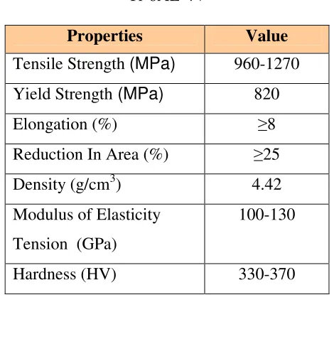
Titanium alloy, Ti-6Al-4V was used as the workpiece material. The workpiece was prepared into rectangular shape with dimension 153mm x 78mm and 10mm thickness. The mechanical properties and chemical compositions of the material are shown in Tables 2.1and2.2respectively.
All the drilling trials were conducted on a Mazak VARIAXIS 500-5X CNC machining centre as shown in Figure 2.1. Drilling experiments were carried out at various cutting speeds of 50, 60 and 70m/min with constant feed of 0.1mm/rev in direct and peck drilling modes.
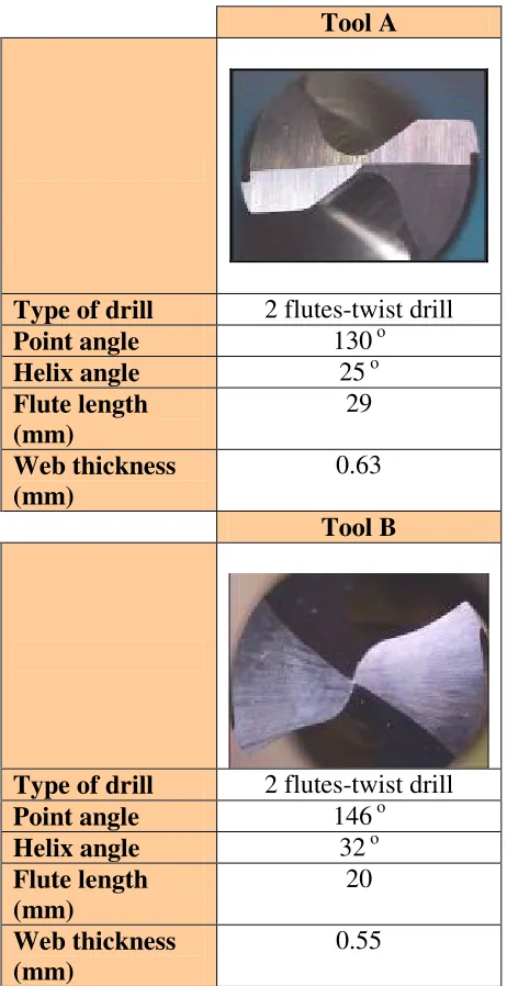
The type of cutting tool used was solid uncoated carbide tool (WC/Co) drills with diameter 6 mm. The drill geometry and detail specifications are shown in Table 2.3.
Table 2.1: Mechanical properties of Ti-6AL-4V
Properties Value
Tensile Strength (MPa) 960-1270
Yield Strength (MPa) 820
Elongation (%) ≥8
Reduction In Area (%) ≥25
Density (g/cm3) 4.42
Modulus of Elasticity
Tension (GPa)
100-130
[image:2.612.313.573.91.723.2]Hardness (HV) 330-370
Table 2.2: Chemical composition of Ti-6AL-4V (Wt %)
Al V Fe C Mo Mu Si Ti
6.37 3.89 0.16 0.002 <0.01 <0.01 <0.01 Balance
[image:2.612.315.550.109.351.2]Table 2.3: Specification of the drills.
Tool A
Type of drill 2 flutes-twist drill
Point angle 130 o
Helix angle 25 o
Flute length (mm)
29
Web thickness (mm)
0.63
Tool B
Type of drill 2 flutes-twist drill
Point angle 146 o
Helix angle 32 o
Flute length (mm)
20
Web thickness (mm)
0.55
Without dismounting the drill from the tool holder, the tool wear was measured using a Nikon toolmakers’ microscope at 30× magnification. The experiment was stopped after drilling at the 25th hole or until the tools met any one of the following tool life criteria; average non-uniform flank wear ≥0.15 mm, maximum flank wear ≥0.2 mm, chipping ≥0.2 mm or catastrophic failure. In
this study, the tool specimens were prepared to investigate the tool wear patterns and failure modes.
The SEM equipped with Energy Dispersive X-Ray Spectroscopy (EDAX) was used under various magnifications to capture the appropriate tool wear images and to determine the elements that adhered on the worn tools.
3. Results and Discussion 3.1 Tool life
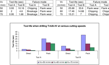
The effect of various cutting speeds on the tool life for both types of drill with different type of drilling modes (direct and peck) are shown in Tables 3.1 and 3.2, and
Table 3.1: Tool life and tool failure mode data for direct drill at 0.1mm/rev
Vc Tool life (sec) Failure mode (m/min) Tool A Tool B Tool A Tool B
50 3.93 10.16 Chipping Flank wear
60 2 4.6 Breakage Flank wear
70 0.95 1.68 Breakage Flank wear
Table 3.2: Tool life and tool failure mode data for peck drill at 0.1mm/rev
Vc Tool life (sec) Failure mode (m/min) Tool A Tool B Tool A Tool B
50 25.68 33.6 Flank wear Flank wear 60 17.46 14.88 Chipping Chipping
70 15.21 7 Chipping Chipping
Figure 3.1: Comparison of tool life when drilling Ti-6Al-4V with Tool A and Tool B at various cutting speeds, at constant feed rate of 0.1 mm/rev for direct and peck drilling.
Tool life when drilling Ti-6Al-4V at various cutting speeds
0 5 10 15 20 25 30 35 40
Direct Peck Direct Peck
Tool A Tool B
T
o
o
l
li
fe
(
s
e
c
)
Vc=50 m/min Vc=60 m/min Vc=70 m/min
Figure 3.2: Flank wear versus cutting time when direct drilling Ti-6Al-4V with Tool A and Tool B at various cutting speeds and at constant feed rate of 0.1mm/rev.
Flank Wear Versus Cutting Time at Feed Rate of 0.1mm/rev for Tool A and Tool B (Direct)
0 0.05 0.1 0.15 0.2 0.25 0.3
0 2 4 6 8 10 12
Cutting time (sec)
F
la
n
k
w
e
a
r,
V
b
(
m
m
)
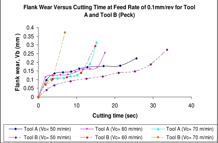
[image:4.612.126.500.465.663.2]3.2 Tool Wear and Failure Mode Figures 3.2 and 3.3 show the development of tool wear for Tool A and Tool B respectively at various cutting speeds; 50, 60 and 70m/min. It was found that the tool wear rate for Tool B grow gradually when compared with Tool A. All the drills experienced a premature failure under 1 minute of cutting time. As a result, fewer holes were produced when using Tool A. Tool A experienced breakage when direct drilling after the 2nd hole at cutting speed of 60m/min. At 70m/min, rapidly breakage occurred after drill the 1st hole. Unlike Tool A, Tool B exhibited a lower tool wear rate as shown in Figures 3.2 and 3.3. It can be seen that initially the flank wear grew steadily and increased as drilling continues.
Non-uniform flank wear and micro chipping were also observed in Tool B during direct drilling for the entire cutting speeds. Figure 3.1 also shows that non-uniform flank wear and micro chipping were observed in Tool A when peck drilling at all cutting speeds. Adhered titanium material was observed on the flank face of the drill. This is well expected since titanium has a tendency to weld to the cutting tool during machining and may promote chipping at the cutting edges after extended drilling [14,15]. According to Sharif et al. [15], the major contributors to the occurrence of chipping of the cutting edge were adhesion and attrition wear.
Figure 3.3: Flank wear versus cutting time when peck drilling Ti-6Al-4V with Tool A and Tool B at various cutting speeds and at constant feed rate of 0.1mm/rev.
Flank Wear Versus Cutting Time at Feed Rate of 0.1mm/rev for Tool A and Tool B (Peck)
0 0.05 0.1 0.15 0.2 0.25 0.3 0.35 0.4
0 10 20 30 40
Cutting time (sec)
F
la
n
k
w
e
a
r,
V
b
(
m
m
)
Tool A (Vc= 50 m/min) Tool A (Vc= 60 m/min) Tool A (Vc= 70 m/min)
[image:5.612.109.475.81.322.2]
4. Conclusions
1. Tool B gave the best tool life
performance when drilling Ti-6Al-4V at the lower cutting speed of 50m/min during peck drilling. Therefore, lower cutting speed and peck drill (method of drilling) should be employed when drilling Ti-6Al-4V in order to achieve better tool life performance.
2. Tool wear was found to develop
progressively with cutting time at low cutting speed when drilling Ti-6Al-4V using both methods of drilling. However, at high cutting speed, the tool failed rapidly with regardless of the drilling methods.
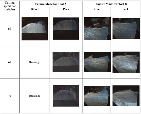
Failure Mode for Tool A Failure Mode for Tool B
Cutting speed, Vc
(m/min) Direct Peck Direct Peck
50
60 Breakage
70 Breakage
[image:6.612.71.544.92.475.2]3. The dominant tool failure mode when peck drilling Ti-6Al-4V for Tool B was excessive chipping. Meanwhile, non-uniform flank wear and micro-chipping were the dominant failure for Tool A in direct drilling and Tool B in peck drilling. However for Tool A, the tool rapidly broke after drilling few holes when direct drilling was applied.
Acknowledgement
The authors would like to thanks to the Ministry of Science, Technology and Innovation, Malaysia for the financial support under the Science Fund Grant (Vote no: S003) and Universiti Tun Hussein Onn Malaysia (UTHM).
References
[1] E.O. Ezugwu, J. Bonney, Y. Yamane, An Overview of the Machinability of
Aeroengine Alloys, J. Mater. Process.
Technol. 134 (2003) 233-238.
[2] E.A. Rahim, S. Sharif, Tool Failure Modes and Wear Mechanism of Coated Carbide Tools When Drilling Ti-6Al-4V.
Int. J. Precision Technology. 1,1 (2007) 30-39.
[3] E.O. Ezugwu, Z.M. Wang, Titanium
Alloys and Their Machinability- A
Review, J. Mater. Process. Technol. 68
(1997) 262-274.
[4] W. Konig, Applied Research on the
Machinability of Titanium and Its Alloys,
Proc. Of the Advanced Fabrication Processes (AGARD), 1-9.
[5] A.R. Machado, J. Wallbank, Machining
of Titanium and Its Alloy-A Review,
Proceedings Institution of Mechanical Engineers, Vol. 204, pp.53-60.
[6] S. Sharif, V.C. Venkatesh, E.A. Rahim,
The Effect of Coatings on the
Performance of Carbide Tools When
Drilling Titanium alloy Ti6Al4V, 8th
CIRP International Workshop on
Modelling of Machining Operations, Chemnitz, Germany. (2005) 557-581.
[7] R. Komanduri, B.F. Turkovich, New
Observations on the Mechanism of Chip Formation When Machining Titanium
Alloys, Wear, 69 (1981) 179-188.
[8] P.A. Dearnley, A.N. Grearson, Evolution of Principal Wear Mechanisms of Cemented carbides and Ceramics Used
In Machining Titanium Alloys IMI 318,
Journal of Material Science and
Technology, 2 (1986) 47-58.
[9] A. Jawaid, C.H. Che-Haron, A. Abdullah,
Tool wear Characteristics in Turning of
Titanium Alloy Ti-6246, J. Mater.
Process. Technol. 92-93 (1999) 329-334.
[10] N. Narutaki, A. Murakoshi, H.
Takeyama, Study in Machining of
Titanium Alloys, CIRP Annals, 32 (1983)
65-70.
[11] C.H. Che-Haron, Tool Life and Surface
Integrity in Turning Titanium Alloy, J.
Mater. Process. Technol. 118, 1-3 (2001) 231-237.
[12] E.O. Ezugwu, R. B. Da Silva, J. Bonney,
A.R. Machado, Evaluation of the
Performance of CBN Tools When Turning Ti-6Al-4V Alloy With High
Machine Tools and Manufacture, 45, 9 (2005) 1009-1014.
[13] E.O. Ezugwu, I.R. Pashby, The Milling of Titanium and Nickel Base Superalloys
With TiN/Steel Composite End Millings,
International Conference on the
Behavior of Material in Machining, York, England. (1991) 96-102.
[14] A. Jawaid, S. Sharif, S. Koksal,
Evaluation of Wear Mechanisms of Coated Carbide Tools When Face
Milling Titanium Alloy, J. Mater.
Process. Technol. 99, 1-3 (2000) 266-274.
[15] S. Sharif, A. Jawaid, S. Koksal, Effect of Edge Geometry On Coated Carbide Tools When Machining Face Milling
Titanium Alloy, Intternational journal for
Manufacturing Science and Technology 2, 2 (2000) 11-17.
[16] W. Min, Z. Youzhen, Diffusion Wear
in Milling Titanium Alloys, Journal of
Material Science and Technology 4 (1988) 548-553.
[17] L.N. Lopez, J. Perez, J.I. Llorente, J.A. Sanchez, Advanced Cutting Conditions
for the Milling of Aeronautical Alloys,
Journal of Materials Processing
Technology. 100, 1-3 (2000) 1-11.
[18] K. Sakurai, K. Adichi, T. Kamekawa, R. Niba, Drilling of Ti6Al4V, Journal of japan Institute of Light Metals. 42,7 (1992) 389-394.
[19] A.L. Matle, D.K. Aspinwall, O.
Wollenhofer, Twist Drill of Gamma
Titanium Aluminade Intermetallics,
Proceedings of 12th Conference of the Irish Manufacturing Committee, Dublin, Ireland. (1995) 229-236.
[20] M. Arai, M. Ogawa, Effect of High Pressure Coolant in Drilling of Titanium
Alloy, Journal of Japan Institute of Light
Metals. 47, 3 (1997) 139-144.
[21] K. Fujise, T . Ohtani, Machinability of Ti-6Al-4V Alloy in Drilling With Small
Drills, Proceedings of Cutting and