Performance Evaluation of Downdraft Gasifier for
Generation of Engine Quality Gas
Anil Kumar
*, Raj Kumar
Department of Mechanical Engineering, YMCA University of Science & Technology, Faridabad-121006, India *Corresponding Author: [email protected]
Copyright © 2013 Horizon Research Publishing All rights reserved.
Abstract
The use of renewable energy resources is broadly increasing for power generation, so the engine quality producer gas which comes from gasifier must be evaluated for engine applications. The Internal Combustion Engine (ICE) generates electricity for lighting & other end uses. The system consists of a gasifier coupled with ventury scrubber, coarse filter filled with wood chips; two fine filters filled with saw dust and one security fabric filter. The gases produced are cooled in water scrubber and then tar is removed in subsequent filters and gases are supplied to Spark Ignition Engine for operating AC Generator set. The unit is tested with resistive loading, which increases gradually from 20 %, 40 %, 60 %, 80 % & 100%. The cold and hot gasification efficiencies are 75.41% & 80.85 % respectively. The biomass consumption rate is 27kg/h. The air and gas flow rate are measured 20.79 m3/h and 79m3/h respectively.The temperature above the grate is 603℃. The tar level after gas cooling and cleaning unit is counted 9 mg/Nm3.Keywords
Renewable Energy, Biomass, Producer Gas, Tar Level, Grate Temperature, Gasifier1. Introduction
Though producer gas as a fuel has been known since 1785, gasifier use with engines for power generation came into existence only around 1920. The IInd world war created a very large demand of power. Maximum Gasification development activities were carried out during this period due to the shortage of fossil fuels. The possibilities of using this gas for heating and power generation was first realized by Europe, therefore this gas emerged in Europe producer gas system which used charcoal and peat as feed material.
Sims [1] suggested the wood biomass as a greatest potential fuel for electricity generation in New Zealand. Narvaez [2] reported biomass gasification with air and effect of several variables on performance of gasifier. Delgado [3] discussed the cleaning of raw producer gas using cheap
calcined materials and rock downstream from gasifier. Hasler [4] showed the tar reduction efficiency of cleaning system must be 90% for satisfactory operation of IC engine. The dry sand bed was used to remove additional tar and dust from gas. Mukunda [5] suggested the use of dry sand filters after a wet scrubber to be an effective way of removing particulates and tar from producer gas. Ministry of Non-Conventional Energy Source [6] has represented the protocol of measurement of the upper limits for tar and dust or particulates content of the producer gas, which are as follows:
Tar
=
100
mg
/
Nm
3 Dust=
50
mg
/
Nm
3Total tar
+
Dust content<
150
mg
/
Nm
3Chen[13] reported that not only the biomass characteristics but also present technology is also responsible for fuel gas production from biomass. A characteristics modeling approach had been addressedto encounter the challenges of present gasification technology. Beenackers [14] presented a review of moving bed biomass gasifier for its high performance. It is commercially available in European Union.
The most biomass materials are found in developing countries like Africa and Asia so it would be most viable for energy in the developing countries. However, in recent years, developed countries in Europe have showed interest and promoted the use of biomass as fuel [15-19]. Hence, the biomass has aroused the interest not only of developing countries but also of developed countries. Stahl [20] depicted the Sweden has been continue investing in biomass energy program since Second World War. The difficulties faced during the Second World War have always been constant reminder to the Swedes and it must be for most countries in the world, which depends upon imported fossil fuel.
2. Materials and Methods
2.1. System Description
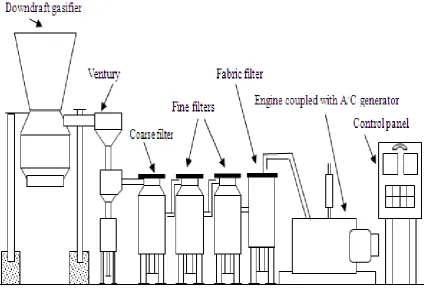
The downdraft gasifier is introduced into the system, in which the air and biomass flow take place in the same direction.The biomass is fed through the feed door and is stored in the hopper. The limited and controlled amount of air for partial combustion enters above the oxidation zone through air nozzles. The Reactor holds charcoal for reduction of partial combustion products while allowing the ash to drop off in the ash pond. The gas passes through the annulus area of reactor from upper portion of the perforated sheetand exit at the bottom of gasifier. This type of gasifier produces the tar free producer gas which is the main advantage, while the major disadvantage is the necessity to process the biomass to avoid excessive drop of pressure. In addition, the efficiency is low and not practical to be used for capacity more than 350kW.
The producer gas outlet of gasifier is connected with the various downstream systems viz. Ventury scrubber, Drain box, Coarse Filter, Flare with valve, Engine gas control valve, Fine filters, Safety filter and Engine shut-off valve. Gas produced in Gasifier is scrubbed and cooled in Ventury Scrubber with re-circulating cooling water in cooling pond with the help of AC scrubber pump. Gas is separated from water in Drain box and introduced in Coarse Filter, Fine Filters (active and passive) and a Safety Filter. Cool, Clean Gas and Air is then sucked into the Engine through a mixer butterfly consisting of piping and valves arrangement. The producer gas then starts engine on gas mode. Governor linked control butterfly is provided to vary the gas quantity
as per electrical load on the generator, keeping frequency within limits. An electric driven biomass cutter and reactor heat recovery based wood pieces drying arrangement are also provided to make the system self-sufficient.
2.2. Methods Used 2.2.1. Fuel
The biomass used for testing of the gasifier is firewood chips of approx size 60×45×25mm3 having moisture 12%. 2.2.2. Loading Device
The loading device is developed, having 47 bulbs of 500W capacity each. These bulbs are well distributed on each phase kept ON or OFF to load the engine gradually.
2.2.3. Measurement of Tar
The tar samples are collected in copper tube condenser dipped in ice bath. The length of condenser is 5m .The temperature of water bath in which condenser is placed, was maintained to be 5±10C to cool the gasses passing through the condenser. This tar is collected by the displacement method in which it is displaced for the 100 liters of water and then it is cleaned by acetone from the condenser.
2.2.4. Biomass Consumption Rate
The biomass consumption per hour of the gasifier operation was estimated by dividing the weight of total biomass poured in the gasifier with the total time of operation
2.2.5. Gas Analysis
The producer gas leaving the gasifier was collected in the gas samplers and analyzed using gas chromatograph. The make of gas chromatograph is “CHEMITO, Model No.8510" collaboration with USA.
2.2.6. Measurement of Temperature
The temperature profile of the gasifier was measured using chromel-alumel thermocouple at 8 different locations above the grate. The temperature at the inlet and outlet of the ventury scrubber & filters were measured by thermocouples (J-type) make “EMSON Pvt. Ltd. Ajmer”. These thermocouples were fitted into the Data logger for measurement of the temperature. The make of Data logger is “DATA TAKER, Model No.-DT600 and Series3”.
2.2.7. Measurement of Pressure
Figure 1. Schematic diagram of downdraft gasifier coupled with engine
3. Results and Discussion
For evaluating the downdraft gasifier, the system was continuously operated with mixed wood for more than eight hours in a day during test. The temperature inside the reactor was measured 145mm, 165mm, 185mm, 205mm and225mm above the grate using the thermocouple were 603℃, 585℃, 544℃, 519℃ and 408℃ respectively which is shown in fig.2. This graph is indicating the steady state of equilibrium in gasifier at particular height for stability in operation. The temperature of grate was recorded approximately 1200℃.
The tar level in the producer gas as shown in fig.3, was measured 230mg/Nm3 at the outlet of gasifier and after, all outlets of the filters, coarse filter, active filter, passive filter and security filter or cleaning unit were 78 mg/Nm3,46 mg/Nm3,18 mg/Nm3,9 mg/Nm3. The fig.3 is showing the time of cleaning of filters. In the form of efficiency, the fabric filter is most efficient.
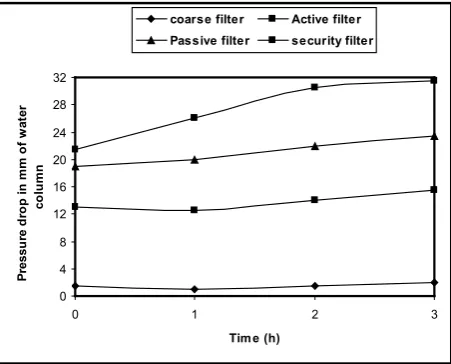
[image:3.595.324.540.404.561.2]Fig.4. shows the variation in pressure with respect to time for the different filters, it has been approximately constant after the stabilization of the plant up to the maximum output. The increasing order of pressure is indicating the cleaning of producer gas.
[image:3.595.322.543.590.737.2]Figure 2. Temperature profile of reactor above grate
Figure 3. Variation in tar content with respect to time
250 350 450 550 650
140 150 160 170 180 190 200 210 220 230 240 250 260 270
Height above the grate (mm)
T
em
p
er
at
u
re o
f t
h
e r
eact
o
r (
o
C
)
0 30 60 90 120 150 180 210
0 1 2 3 4 5
Time (h)
Ta
r (
mg
/N
m3
Figure 4. Variation in pressure of filters with respect to time Fig.5. Shows the volume flow rate of air and producer gas production rate is increasing with respect to the time. It means the design considerations are better for downdraft gasifier.
Figure 5. Variation in volume flow rate of air and producer gas with respect to time
Figure 6. Variation in cold and hot efficiency at different loads
[image:4.595.318.548.180.348.2]Fig.6. shows variation in cold gasification efficiency and hot gasification efficiency with respect to load. The load is varying from 4.5kW to 18kW, while the cold and hot gasification efficiency increases from 67.5% to 75.41% and 69.55% to 80.85% respectively. It is reflecting the improvement in quality of producer gas, which can be used efficiently in electric power production and in internal combustion spark ignition engine for various applications.
Figure 7. Variation in biomass consumption rate at different loads
Fig.7. depicts the biomass consumption rate is increasing with respect to increase in load. It is due to increase in the biomass gasification. When the load increases the demand of producer gas also increases in internal combustion engine so maximum amount of biomass will be burnt in gasifier and biomass consumption rate will increase with increase in load. The biomass consumption rate is measured 27 kg/h at maximum load.
4. Conclusion
The performance evaluation of the downdraft gasifier through the above discussion is clearly indicating the following conclusions:
(1). Wood is found to be effective fuel for generation of producer gas.
(2). The pressure drop across the filters increases with duration of operation, which indicates that the moisture, tar and particulates being filtered out from the producer gas.
(3). The fabric filter is most efficient filter. The value of tar after this filter is 9 mg/Nm3.
(4). The grate temperature was nearly 12000C, which is adequate for proper gasification.
(5). The cold and hot gasification efficiencies are 75.41% & 80.85 % respectively. It is showing satisfactory working of gasifier.
(6). The air and producer gas flow rate into the gasifier, temperature profile are gradually increasing with time and become stable in some time. It reflects that 0 4 8 12 16 20 24 28 32
0 1 2 3
Time (h) Pr essu re d ro p i n m m o f w at er co lu m n
coarse filter Active filter
Passive filter security filter
10 12 14 16 18 20 22
0 0.5 1 1.5 2 2.5 3
Time (h) V o lu m e f lo w r at e o f a ir (m 3/ h ) 30 35 40 45 50 55 60 65 70 75 80 V o lu m e f lo w r at e o f p ro d u ce r g as ( m 3/ h )
Air flow rate Producer gas flow rate
68 70 72 74 76
20 30 40 50 60 70 80 90
Percentage of load (%)
C ol d g as ifi ca tio n ef fici en cy ( % ) 71 73 75 77 79 81 H ot g asi ficat io n ef fici en cy ( % )
Cold gasification efficiency Hot gasification effiency
10 15 20 25 30
20 30 40 50 60 70 80 90
Percentage of load (%)
[image:4.595.62.293.350.523.2] [image:4.595.62.291.565.736.2]the quality of producer gas improves when the system is operated for longer duration.
(7). The gasification system can be used as a small power unit to meet the thermal and electrical needs. There is a huge scope to save the fossil fuel.
The performance of the gasifier for power generation with spark ignition engine has demonstrated technically feasible and indicating to meet the requirement of engine quality producer gas.
REFERENCES
[1] REH. Sims. Electricity generation from wood biomass fuels compared with other renewable energy options, World Renewable Energy Congress, Reading, 1994.
[2] I. Narvaez, A. Orio, M.P. Aznar, J. Corella. Biomass gasification with air in an atmosphere bubbling fluidized bed. Effects of six operational variables on quality of the produced raw gas, Industrial & Engineering Chemistry Research, Vol. 35, No. 7, 2110-2120, 1996.
[3] J. Delgado, M.P. Aznar, J. Corella. Biomass gasification with steam in fluidized bed: effectiveness of CaO, MgO and CaO-MgO for hot raw gas cleaning, Industrial & Engineering Chemistry Research, Vol. 36, No. 5, 1535-1543, 1997. [4] P. Hasler, T. Nussbaumer. Gas cleaning for IC engine
applications from fixed bed biomass gasification, Biomass Bioenergy, Vol. 16, 1999.
[5] H.S. Mukunda, S. Dasappa, P.J. Paul, N.K.S Rajan, U. Shrinivasa. Gasifiers and combustors for biomass-technology and field studies, Energy Sustainable Development, Vol. 1, No. 3, 1994.
[6] Qualifying, testing and performance evaluation of biomass gasifiers and gasifier-thermal systems. Test procedures, methodology and protocols. Ministry of Non-Conventional Energy Sources, Government of India, (Prepared by Indian Institute of Technology, Bombay); 2000.
[7] M. Hellwig. Basic of combustion of wood and straw, in Energy form biomass Conference, EEC/Elsevier, 793-798, 1982.
[8] F. Centeno, K. Mahkamov, E.E.S. Lora, R.V. Andrade. Theoretical and experimental investigations of a downdraft biomass gasifier-spark ignition engine power system,
Renewable Energy, Vol.37, 97-108, 2012.
[9] P. McKendry. Energy production from biomass (part 1): overview of biomass, Bioresource Technology, Vol. 83, 37–46, 2002.
[10] D.J. Gielena, M.A.P.C. De Feber, A.J.M. Bos. Biomass for energy or materials? A western European systems engineering perspective, Energy Policy, Vol. 29, 291-302, 2000.
[11] T.B. Johansson, H. Kelly, A.N. Reddy. Renewable energy sources for fuel and electricity, Petroleum Industry Press, Beijing, 170-184, 2000.
[12] W. Murphey, K. Masters. Gross heat of combustion of northern red oak chemical components, Wood Science, Vol. 10, No. 3, 139, 1978.
[13] G. Chen, J. Andries, H. Spliethoff. Biomass conversion into fuel gas using circulating fluidised bed technology: the concept improvement and modelling discussion, Renewable Energy, Vol. 28, 985–994, 2003.
[14] AACM. Beenackers, Biomass gasification in moving beds, a review of European technologies, Renewable Energy, Vol. 16, (1-4 pt 2) 1180-1186, 1999.
[15] J. Nieminen, M. Kivela, Biomass CFC connected to a 350 MW/T/H steam boiler fired with coal and natural gases-THERMIE demonstration project in Lahti in Finland, Biomass Bioenergy, Vol. 15, No. 3, 251-257, 1998.
[16] A. Mory, T. Zotter, EU-demonstration project BIOCOCOMB for biomass gasification and co-combustion of the product-gas in a coal-fired power plant in Australia, Biomass Bioenergy, Vol. 15, No. 3, 239-244, 1998.
[17] H.J. De Lange, P. Barbucci, THERMIE energy farm project, Biomass Bioenergy, Vol. 15, No. 3, 219-224, 1998. [18] A. Faaij, J. van Doorn, T. Curvers, L. Waldheim, E. Olsson, A
van Wijk, C. Daey-Ouwens, Characteristics and availability of biomass waste and residues in the Netherlands for gasification, Biomass Bioenergy, Vol. 12, No. 4, 225-240, 1997.
[19] A. Olivares, M.P. Aznar, M.A. Caballero, J. Gil, E. Frances, J. Corella, Biomass gasification: produced gas upgrading by in-bed use of dolomite, Industrial & Engineering Chemistry Research, Vol. 36, No.12, 5220-5226, 1997.