International Journal of Emerging Technology and Advanced Engineering
Website: www.ijetae.com (ISSN 2250-2459, ISO 9001:2008 Certified Journal, Volume 3, Issue 6, June 2013)
377
Design Proposal for Optical Data Bus Network for Small
Aircraft
Nikhil Verma
1, Md. Easir Arafat Papon
2, Akhter Mahmud Nafi
3 IIAF, Instructor Class-A, Dept. of Aeronautical Engg. Military Institute of Science & Tech, Dhaka
2Lecturer, Dept. of Aeronautical Engg. Military Institute of Science and Technology (MIST), Dhaka 3Undergraduate student, Aeronautical Engg. Dept, MIST, Dhaka
Abstract—With the development of the avionics system, integrated avionics architecture is desirable for the next generation of high performance aircraft. In this regard we have proposed a data bus network for small aircrafts to meet the demand of bandwidth, data transmission rate, immunity to electromagnetic interference, weight and size. This paper describes about the proposal, word format, data generation processes and reasons behind choosing such a network. It also describes technical specifications to show the optical fiber based network as a reliable and modular system for use in aircrafts.
Keywords—Avionics network, data bus, federated architecture, Optical fibre, reliability, failure rate.
I. INTRODUCTION
Avionics industry is undergoing rapid changes over the years. Network standards are also been upgraded according to the requirements as well. The functional requirements relate to capability of the network in transporting data from source to destination and involve parameters such as throughput, latency, fault tolerance, bit-error rates etc. and the guarantee of reliable information flow. All these aspects make the process selection of on board avionics network difficult. Optical fiber based networks provide greater bandwidth, excellent data transmission rate, enhanced immunity to electromagnetic interferences and less weight and size and therefore, the performance of optical network can meet the demand of avionics system developments [1]. Integrated digital avionics data transmission networks allow data multiplexing, transmission/reception and communication of on-board avionics data in modular avionics architecture. In vogue, data bus protocols are: ARINC 429, ARINC 629, MIL-STD 1553, MIL-STD 1773, Commercial Serial Digital Bus (CSDB) and Avionics Serial Communication Bus (ASCB) [1]. For small aircrafts where parameters to be considered are less, we are proposing an optical fiber based avionics data bus network, related calculations, results for reliability and failure rate which proves the capability of the proposed network in this regard.
II. SELECTION OF BUS NETWORK
There are different types of networks which can be used in avionics network [2]. Choosing the basic network is the first and the most fundamental challenge faced by the designer. Considering the requirements of proposed architecture for small aircraft we select bus architecture. For small aircraft we need a network that is suitable for limited no. of avionics equipment, flexible for future expansion and provide redundancy. Bus topology fulfills that requirement. It also allows less number of cables in design. Redundancy is the most important factor in avionics network. Bus topology is redundant because failure of a single device doesn’t bring the entire network. It is inexpensive and simple network and very easy to extend the network by adding cable with a repeater that boosts the signal and it allows it to travel a longer distance [1, 2].
III. REASONS BEHIND SELECTING FEDERATED
ARCHITECTURE
International Journal of Emerging Technology and Advanced Engineering
Website: www.ijetae.com (ISSN 2250-2459, ISO 9001:2008 Certified Journal, Volume 3, Issue 6, June 2013)
378 IV. SELECTION OF AVIONICS COMPONENTS FOR
PROPOSED DATA BUS
It is proposed that a single engine small aircraft would necessarily need following major avionics equipments- Master computer, Backup Master Computer, Inertial navigation platform, Multifunction Display, Air Data Computer (ADC), Global Positioning System (GPS), Engine Monitoring Unit and Radio Communication sets. Master computer is the key in avionics data bus system which constantly monitors the data bus, controls the data flow and traffic on the bus. Backup master computer acts as a hot standby. Inertial navigation platform is a navigation aid which uses a computer, motion sensors and rotation sensors. The proposed data bus has laser gyro as the main component for the inertial navigation platform because of its flexibility of having no moving parts and comparing to conventional spinning gyroscope, this means there is no friction, which in turn means there will be no inherent drift terms. A MFD allows the pilot to display their navigation route, moving map, weather radar and other information related to flight and equipment. ADC which is used to acquire and process analog data into digital from different sensors to obtain parameters such as airspeed, altitude, temperature, angle of attack etc. also need a highly reliable data bus network along with GPS which is mainly a ranging system calculates ranges and position of an object using coordinate system. Apart from this, engine control unit and various Nav-aids like ILS, VOR, DME etc. need a high bandwidth data link which need to be light weight, immune to electromagnetic interference and highly reliable [3,4,5].
V. PROPOSED OPTICAL FIBER BASED AVIONICS DATA BUS
[image:2.612.310.586.149.565.2]The proposed data bus network for a small engine aircraft is shown in figure 1. The data bus is configured in dual redundant form.
Figure 1: Proposed data bus network for a small engine aircraft
Bus A
Bus B
Master Computer
Radio Communication Set
Engine Control System Multifunction
Display or Display Map Bank
ADC
Backup Master Computer
GPS Laser Gyro or
Inertial Navigation Platform
E-O-C converter
Data Bits in Electrical Form Data Transmission in Optical
International Journal of Emerging Technology and Advanced Engineering
Website: www.ijetae.com (ISSN 2250-2459, ISO 9001:2008 Certified Journal, Volume 3, Issue 6, June 2013)
[image:3.612.56.271.292.601.2]379 All equipments generate electrical signals, electrical to optical converter (E-O) coverts the electrical data in optical form and transmission data bus in a full duplex format. Bus traffic or data throughputs travels along the bus in words. The signal can be Manchester bi-phase encoded. High availability environments require redundancy on the bus as well as within equipments. All avionics equipments are connected to both of the buses. Data is available in both buses in real time and in case of failure of one bus; other can support the entire system. The bus conflict will be resolved by an arbitration using the identifier and the lowest identifier transmission will be delayed [6]. The process is shown in figure 2.
Figure 2: Flow chart of data transmission process
VI. WORD FORMAT
A data word in proposed data bus would be a sequence of 16 bits consisting of 1 bit for sync wave, 14 bits of data and 1 parity check bit, as shown in table 1.
TABLE 1
WORD FORMAT OF PROPOSED DATA BUS
Sync Data (Depending upon word type) Parity
1 2 3 4………..13 14 15 16
[image:3.612.318.572.322.418.2]The sync and parity bit are added before transmission and remove during reception. Therefore the nominal word size is 14 bits with the most significant bit (MSB) first. There are mainly two types of words: command word and data word. Command words are generated by the every equipment of data bus. It consists of 16 bits with recipient address, sender identification and data word count shown in table 2.
TABLE 2 COMMAND WORD
Sync
Sender identificatio
n
Txr/ Rxr
Receiver identificati
on
Data Word Count
Parity Check
1 2 3 4 5 6 7 8 9 10 11 12 13 14 15 16
Data word count is 4 bit, so after every command word, a component can transmit maximum 24 or 16 data words. Command word has 4 bits for recipient addresses it can support 24=16 equipments at a time. It has 4 bits for data word count so one equipment can ‘talk’ max 24 =16 words simultaneously. The small message size results in very low latency, minimizing delays during processing and guaranteeing timing, as no transport side queuing or rescheduling of traffic can happen. The message size is one of the cornerstones for achieving safety, resilience and reliability [4,9, 13].
VII. DATA GENERATION BY DIFFERENT TYPES OF
AVIONICS SYSTEMS
Every component would generate digital data and it passes through the data bus. In order to obtain the reliability and error rate data generated needs to be ascertained. Range of the measurement means the difference between the largest and the smallest value that respective sensor can measure. Proposed data bus has 14 bits for data. 2’s complement method is used for converting decimal value into binary.
Initially transmitted data from any equipment
Identify the sender
Is the sender priority is greater?
Greater ?
Yes
Complete the process
International Journal of Emerging Technology and Advanced Engineering
Website: www.ijetae.com (ISSN 2250-2459, ISO 9001:2008 Certified Journal, Volume 3, Issue 6, June 2013)
380 If the range is too big to be represented in 14 bits, then two data word of 14 bits each are used, one for magnitude and one for decimal. If one set of 14 bit fails to represent the magnitude, then 2 sets of 14 bit will be used to ensure precision in data generation. For the highest value of the component we don’t need numbers after decimal. But maximum use of 14 bits will occur when the penultimate unit with decimal value will be represented. So, that value will be the maximum value represented in 14 bits [6, 8, 9].
In order to calculate the throughput of the system, operating frequency of the components and sampling rate are considered to get total generated bits. There would be additional data generated by the system based on the measured parameter. Like synchronization, system measurement, fault diagnosis etc. However, for simplification in the initial calculations of data throughput there are not considered. Operating frequency of a component is the rate of information it generates in every second, sampling frequency defines the number of samples per unit of time taken from a continuous signal to make it a discrete signal.
Each equipment may be assigned a unique memory address and priority is being set as well. The table 3 shows proposed memory addresses and priority for each equipments.
TABLE 3
MEMORY ADDRESSES & PRIORITY ALLOCATION FOR AVIONICS EQUIPMENT
Based on the memory addresses, data characteristics, conversion error and data generation of all avionics equipment are given bellow:
A. Master Computer (MC) & Backup Master Computer
It is having the 1st priority and memory address is 0000. Assuming operating frequency 10 MHz, total bits generated per second,
=14×10×106 Mbps or 140 Mbps
Backup master computer will have same to same data out as MC, as it works as hot standby.
B. Inertial Navigation Platform
Its having the 3rd priority and address is 0010. Major equipment to be taken into consideration is Laser Gyro having range of ±300 degree [6]. We need values up to 2nd place of decimal to represent laser gyro data. If we represent the maximum value of equipment in 14 bits with two digits after decimal the conversion error would be 0.03o. In order to minimize the error, two 14 bits words assigned for magnitude whose 1st bit is sign bit and another 1 word for decimal value representation. Minimum & Maximum value at all 14 bits: ±299.99o. Minimum value
represented in binary is
10000100101011.11111101011100. Maximum value in
binary representation is
00000100101011.11111101011100. Maximum error in conversion is 0.01o
Assuming, operating frequency 300 Hz (100Hz for each 3 axis) of aircraft and a sampling rate 2×300Hz, the inertial navigation platform would generate a minimum of 84 Kbps of data.
C. Air Data Computer
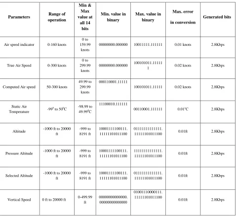
It is having 4th priority and memory address is 0011. Air data computer computes parameters of Air Speed Indicator, True Air Speed, Computed Air Speed, Static Air Temperature, Altitude, Selected Altitude, Pressure Altitude, Vertical Speed etc. [12]. The table shows the overall data throughput and analog to digital conversion limits for Air Data Computer parameters.
These calculations are done assuming operating frequency of 100 Hz. In case of air speed indicator, true air speed, computed air speed, static air temperature we need two places after decimal to represent the data. If we represent the maximum value of equipment in 14 bits with two digits after decimal, there will be 9 digits for magnitude and rest 5 bits for decimal value representation. Likewise, for altitude, pressure altitude, selected altitude and vertical speed, we need 2 values after decimal to represent the data. One set of 14 bits can be assigned for magnitude, whose 1st bit is sign bit. Another 14 bits can represent the value.
Priority Component Memory address
1 Master Computer 0000
2 Backup Master Computer 0001
3 Laser gyro 0010
4 Air Data Computer 0011 5 Engine Monitoring System 0100
6 GPS 0101
7 Multifunction Display 0110
International Journal of Emerging Technology and Advanced Engineering
Website: www.ijetae.com (ISSN 2250-2459, ISO 9001:2008 Certified Journal, Volume 3, Issue 6, June 2013)
[image:5.612.69.547.155.595.2]381
TABLE 4
PARAMETERS AND DATA GENERATION FOR ADC
Parameters Range of
operation
Min & Max value at
all 14 bits
Min. value in binary
Max. value in binary
Max. error
in conversion
Generated bits
Air speed indicator 0-160 knots
0 to 159.99
knots
00000000.000000 10011111.111111 0.01 knots 2.8Kbps
True Air Speed 0-300 knots
0 to 299.99
knots
00000000.000000 100101011.11111
1 0.02 knots 2.8Kbps
Computed Air speed 50-300 knots
49.99 to 299.99
knots
000110001.11111
100101011.11111 0.02 knots 2.8Kbps
Static Air
Temperature -99
0 to 500C -98.99 to
49.990C
11100010.111111
00110001.111111 0.01oC 2.8Kbps
Altitude -1000 ft to 20000 ft
-999 to 8191 ft
10001111100111. 11111101011100
01111111111111.
11111101011100 0.01ft 2.8Kbps
Pressure Altitude -1000 ft to 20000 ft
-999 to 8191 ft
10001111100111. 11111101011100
11111111111111.
11111101011100 0.01ft 2.8Kbps
Selected Altitude -1000 ft to 20000 ft
-999 to 8191 ft
10001111100111. 11111101011100
01111111111111.
11111101011100 0.01ft 2.8Kbps
Vertical Speed 0 ft to 20000 ft 0-499.99 ft
00000000000000. 00000000000000
01001110000111. 11111101011100
0.01ft 2.8Kbps
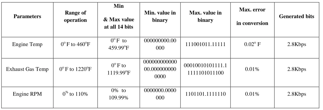
D. Engine Control Unit (ECU)
Engine control unit is the 6th priority avionics component having memory address 0100. Three parameters; engine temperature, exhaust gas temperature and engine RPM are important for aircraft operation.
International Journal of Emerging Technology and Advanced Engineering
Website: www.ijetae.com (ISSN 2250-2459, ISO 9001:2008 Certified Journal, Volume 3, Issue 6, June 2013)
[image:6.612.48.568.156.334.2]382
TABLE 5
PARAMETERS AND DATA GENERATION FOR ECU
Parameters Range of
operation
Min
& Max value at all 14 bits
Min. value in binary
Max. value in binary
Max. error
in conversion
Generated bits
Engine Temp 0o F to 460oF 0 o F to
459.99oF
000000000.00
000 111001011.11111 0.02
o F 2.8Kbps
Exhaust Gas Temp 0o F to 1220oF 0
o
F to 1119.99oF
000000000000 00.000000000
0000
00010010101111.1
1111101011100 0.01% 2.8Kbps
Engine RPM 0% to 110% 0% to 109.99%
0000000.0000
000 1101101.1111110 0.01% 2.8Kbps
E. GPS
GPS is given the 6th priority and having the memory address as 0101. We will calculate for two parameters like latitude and longitude information. Latitude range is ±90o. 4 values after decimal are required to represent the data of latitude. If we represent the maximum value of latitude in 14 bits with two digits after decimal, there will be 8 bits for magnitude and rest 6 bits for decimal value representation. Minimum & Maximum value at all 14 bits is ±89.9999o. Minimum value in binary representation is 1101101.111111 whereas maximum value in binary representation is 0101101.111111. Maximum error in conversion is 0.0156 o. In case of longitude, the range is ±180o. We assign one set of 14 bits for magnitude whose 1st bit is positive or negative sign bit and another 14 bits for decimal value representation. Minimum & Maximum value at all 14 bits in longitude is ±179.9999o and minimum value in binary representation is 10000010110011.11111111111110 whereas maximum value in binary representation is 00000010110011.11111111111110 and maximum error in conversion 0 .0001o. Assuming operating frequency 100 Hz and sampling rate of 2×100 Hz, generated bits would be 2.8Kbps.
Now, for three types of BIT there will be some bits also. [1][2]
1.Start on need 5× 9× 14=630 bps 2.On demand need 5× 9× 14=630 bps 3.Self check need 10× 9× 14=1260 bps
By calculating it is found that there will be 140.1872 Mb data in every second in our proposed architecture.
Assuming 145 Mbps is the maximum throughput in the data bus.
VIII. CONCLUSION
Over the years complexity of avionics systems has increased and also the requirement of high data bandwidth and speed of on-board avionics network. As a result developments are on for commercially adopting optical standards for avionics networks. Hence, in case of small aircraft an optical the data bus network is being proposed. This paper gives a comparative overview of the proposal to be used in a single engine aircraft. From a preliminary assessment of its key features it can be concluded that optical data bus proposal is an easy-to-implement, inexpensive protocol whose reliability may be adequate for most applications in the early ages. There is need to study in depth the hardware and software reliability independently. Various layers of avionics data bus protocols, matching the industrial standards, need further research. Economics of adapting present avionics equipments for optical platform would be a major driving factor. Optical data bus for on board avionics data network would appear to have a promising future.
REFERENCES
[1] Wg Cdr Nikhil Verma, Md. Easir Arafat Papon, A Study of Reliability and Failure Rate for Comparing BIT and non-BIT maintenance cycles in AONA,IJETAE, Volume 3, Issue 2, February 2013.
International Journal of Emerging Technology and Advanced Engineering
Website: www.ijetae.com (ISSN 2250-2459, ISO 9001:2008 Certified Journal, Volume 3, Issue 6, June 2013)
383
[3] Chin E. Lin, S.F. Tai , C.C. Li, H.T Linn & T.P. Chen National Cheng Kung University ,Small Aircraft Avionics using Hybrid Data Bus Technology .
[4] Christian M. Fuchs , Advisors: Stefan Schneele, Alexander Klein, Seminar Aerospace Networks SS2012Chair for Network Architectures and Services ,Faculty of Informatics, Technical University of Munich The Evolution of Avionics Networks From ARINC 429 to AFDX, Seminars FI / IITM / AN SS2012, Network Architectures and Services, August 2012
[5] Herminio Duque Lustosa, EMBRAER and INPE, São José dos Campos, SP, Brazil , Marcelo Lopes de Oliveira e Souza, INPE, São José dos Campos, SP, Brazil, Influences of Data Bus Protocols on An Aircraft Elevator Flight Control Subsystem , IEEE-1-4244-2208, 27th Digital Avionics Systems Conference , October 26-30, 2008 [6] Oscar Acevedo, Dimitri Kagaris, Kaushik Poluri, Harini Ramaprasad
ECE Department., Southern Illinois University, Carbondale, Illinois Shawn Warner, UTC Aerospace Systems, Rockford, Illinois, Towards Optimal Design of Avionics Networking Infrastructures , IEEE- 978-1-4673-1900-3/12 , 31st Digital Avionics Systems Conference October 14-18, 2012
[7] Chin E. Lin, Hung-Ming Yen, Yu-Shang Lin, Department of Aeronautics and Astronautics ,National Cheng Kung University, Tainan, Taiwan 701 Development of Time Triggered Hybrid Data Bus System For Small Aircraft Digital Avionics System , IEEE, 26th Digital Avionics Systems Conference, October 21, 2007
[8] Cary R.Spitzer Digital Avionics Systems- Principles and Practices ISBN: 0-07-060333-2 , page 19-47,119-138.
[9] Ian Moir , Military Avionics Systems , ISBN-10 0-470-01632-9 , page no. 47-82
[10] Chin E. Lin, S.F. Tai, C.C. Li, H.T. Lin & T.P. Chen, National Cheng Kung University, Small aircraft avionics using hybrid data bus technology. IEE A&E Systems Megazine, July 2006
[11] Chin E. Lin, Hung-Ming Yen, Department of Aeronautics and Astronautics, National Cheng Kung, University, Tainan, Taiwan, A prototype dual can-bus avionics system for small aircraft transportation system.. 25th Digital Avionics Conference, October
15, 2006
[12] Chin E. Lin, Hung-Ming Yen, Yu-Shang Lin, Department of Aeronautics and Astronautics National Cheng Kung University, Tainan, Taiwan 701. Development of time triggered hybrid data bus system for small aircraft digital avionic system. 26th Digital Avionics Systems Conference, October 21, 2007