The scope in the INTELCITIES project
for the use of the 3D laser scanner
Arayici, Y, Hamilton, A, Albergaria, P and Gamito, G
Title The scope in the INTELCITIES project for the use of the 3D laser scanner Authors Arayici, Y, Hamilton, A, Albergaria, P and Gamito, G
Type Conference or Workshop Item
URL This version is available at: http://usir.salford.ac.uk/11479/ Published Date 2004
USIR is a digital collection of the research output of the University of Salford. Where copyright permits, full text material held in the repository is made freely available online and can be read, downloaded and copied for noncommercial private study or research purposes. Please check the manuscript for any further copyright restrictions.
Abstract
The difficulty in visualising 2D plans of building elements and components brings about errors in interpreting design specifications in terms of accuracy, completeness. Besides, accessibility is another major problem encountered by surveyors. A number of strategies have been set out to improve efficiency and quality of design within the built environment. One of them is the new innovation of 3D laser scanning technology, which has come about and can be used to improve the efficiency and quality design. It has enormous potential to benefit for refurbishment process.
The scanner can digitise all the 3D information concerned with a building down to millimetre detail. A series of scans externally and internally allows an accurate 3D model of the building to be produced. This model can be "sliced" through different planes to produce accurate 2D plans and elevations. This novel technology improves the efficiency and quality of construction projects, such as maintenance of buildings or group of buildings that are going to be renovated for new services.
This paper describes the generation of 2D and 3D CAD plans of existing buildings. It explains the generation of interior and exterior 2D and 3D CAD plans of the existing facilities. Furthermore, it presents the use of 3D laser scanner in integration with other VR systems such VR workbenches for visualisation, analysis and interaction with a VR model of existing buildings.
Keywords: 3D Laser Scanner, virtual reality, refurbishment, CAD plans, GIS.
1 Introduction
consisting of: Planning, Development, Operation, and Reuse. In order to enhance the implementation of the building solutions during the transformation of the city, the 3D laser scanning technology can be employed.
A key objective is to develop existing systems for use in urban regeneration and integrate them with the laser scanner to attain the benefits of working in a holistic environment. The new integrated system or “Virtual City” will facilitate a holistic approach to problems and thus have a much greater functionality than the individual sub systems [1]. The success of the Virtual City will be validated in terms of its effectiveness in its operation in conjunction with an assessment of the transformations made, within the project, to selected areas of Manchester.
For that, a consortium of researchers and practitioners from 70 different institutions and companies across Europe undertook an EU funded research project called INTELCITIES. Representative systems will be developed to support control and strategic planning improvement and it will be shown how further systems could be produced to form a more widely integrated package.
One of the tasks to achieve the above objective is the building data capture, which is to obtain digital data of existing buildings using the 3D laser scanning technology, i.e to show how this data can be used as an information base to enhance the refurbishment process.
In the next section, the 3D laser scanning technology, its features, advantages and disadvantages are explained.
2 3D Laser Scanning Technology
Systems that measure range from the time-of-flight of a laser pulse have been available for about 25 years, so this does not constitute new technology. However, the development of fast measurement and a scanning mechanism (using rotating mirrors) has only occurred in the past 6 years or so. Packaging these components into a robust and reliable instrument has resulted in the innovation of a 3D laser scanner.
This innovation is significant because it has potential to solve the problems that are always been associated with design and construction of existing buildings for reuse goals. For example, it can provide faster, better quality and more precise analysis and feature detection for building survey. The advantages and disadvantages of this technology is shown in the below table [6].
3D laser scanning technology advantages and disadvantages are summarised in Table 1.
3D Laser Scanning
Advantages Disadvantages
Applicable to all 2D and 3D surfaces Some systems do not work in sun or rain Rapid 3D data collection-near real
time- requiring substantially less site time
Large, high resolution 3D data sets require post-processing to produce a useable output
Very effective due to large volumes of data collected at a predictable precision
Difficulty in extracting the edges examples from indistinct data clouds Ideal for all 3D modelling and
visualisation purposes
Output requires manipulation to achieve acceptable recording quality
Both 3D position and surface reflectance generated which, when processed, can be viewed as an image
No common data exchange format-such as DXF-currently in use to allow ease of processing by third parts
Rapidly developing survey technology Difficult to stay up-to-date with developments
Extensive world-wide research and development currently undertaken on both the hardware and software tools
With hardware still expensive and sophisticated software required to process data, cost is prohibited for many projects
Table 1: Advantages and disadvantages of 3D laser scanning technology
2.1 Features of the 3D Laser Scanner and Software
The University of Salford make use of a Riegl LMS-Z210 3D laser scanner for construction research with PolyWorks software for processing the point data into a 3D model. The LMS-Z210 3D imaging sensor is a rugged and fully portable sensor for the rapid acquisition of high-quality three-dimensional imageseven under highly demanding environmental conditions. The scanner provides a combination of wide field-of-view, high accuracy, and fast data acquisition. The scanner is connected to a 12V battery and a ruggedised laptop.
The high-speed scanner has the following specifications:
o Minimum measurement range = 2 m
o Measurement accuracy = typical +/- 25 mm
o Measurement resolution = 25 mm
o Beam divergence = approx. 3 mrad (i.e. 30cm beam width per 100m range)
o Field of view = 80° vertical angle, 333° horizontal angle
o Scanning rate = 6000 points per second
o Class I eye-safe laser
During data acquisition, the 3D-RiSCAN software is used. It allows the operator to perform a large number of tasks including sensor configuration, data acquisition, data visualization, data manipulation, and data archiving. Numerous export functions allow the scanned data to be passed to post-processing data packages for, e.g., feature extraction or volume estimation [6].
A field methodology has been developed to rapidly capture data for a building survey. For each scanner position, first a scan of the full field of view (333° horizontally) is made to aid merging of data from subsequent scan positions and to aid the definition of detailed scans. This scan takes about 4 minutes. Next, one or more detailed scans are made with a finer resolution of the area of interest (typically the building). This scan typically takes 10 minutes depending on resolution and field of view. This methodology is being extended to incorporate GPS positioning of the scanner.
Once back in the office, PolyWorks software (produced by Innovmetric Software Inc.) provides comprehensive set of tools for quickly processing 3D scanned data [4]. This software has traditionally been used in the manufacturing industries with very short range scanners, but the advent of longer range laser scanners, it has seen widespread use in surveying and architecture, especially within North America. The software can handle many millions of data points while still retaining the ability to model very fine details very accurately.
This will allow scans from each scanner position to be merged together in space. The software will compare geometric features in overlapping areas of adjacent scans to calculate the correct alignment of each scan. This is a very accurate method of aligning laser scan data as it is using many thousands of measurements to make a comparison rather than a few observations that would be made in a conventional surveying scenario.
Next, the 3D mesh model (sometimes termed a wireframe) is created. This 3D mesh uses all the measured data points without applying any dangerous point sampling techniques. In its approach, it uses tolerance-based smoothing and tolerance-based adaptive meshing which provide a robust industrial strength process [5].
number of triangle vertices while retaining as much information as possible (especially on edges).
3 The Need for the Laser Scanner for Building
Refurbishment Process
Undertaking measured surveys and providing plans, elevations and sections of existing buildings and sites remains at the heart of Chartered Building Surveyors. The workload typically involves refurbishing structures and property including restoring historic buildings for which plans are an essential means of communication.
Most surveyors still resort to the use of measuring rods and tapes when taking measurements on site although many now use EDM or similar laser measuring devices. EDM equipment may be used for external measurements. The recording of information on site is traditional undertaken on paper and the technician or Surveyor plotting plans in the office on CAD has to rely on the accuracy, completeness and neatness of the sketches and notes made in the field.
One of the major problem that building surveyors have encountered is the inaccessibility. That is to say, at some occasions, they should measure the details of building and relevant architectural details on the walls due to various reasons, in particular when developing elevation plans. In these circumstances, the building surveyors should estimate the measurements of these details, which is very much likely to involve a variety of errors regarding the accuracy and the actual design of the building due to wrong assumption and judgement.
The use of the 3D Laser scanner has enormous potential to benefit Chartered Building Surveyors and their clients in terms of accuracy, speed and productivity in plan preparation and then to extend the range of services offered through modelling applications. The output of feasibility studies would improve immeasurably with modelling in areas such as assessing disabled access and fire safety. With current demand for whole life costing, asset management planning and database application, Building Surveyors are called upon to link information in CAD files to database files. The possibility of linking this information to 3D models would suggest all sorts of additional benefits.
It is envisaged that using scanners for taking internal and external measurements to provide accurate plans, sections and elevations in far less time than using present methods. These scanners even have the potential to accurately record inaccessible and potentially hazardous areas such as pitched rooftops and workplaces. Building Surveyors look forward then to using this equipment in extending the quality and value of the services presently offered.
4 Scope for the 3D Laser Scanning Technology in the
Project
The scope in the INTELCITIES project includes the integration of the Laser scanning system with the existing or other innovative systems in order to be part in the form of the INTELCITIES prototype system.
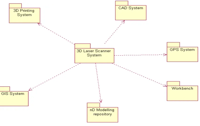
[image:7.595.107.497.406.653.2]Unified Modelling Language [3] is employed for the conceptual modelling of the Laser scanning system and its associations with the other systems including GIS, GPS, Workbench, etc. The figure 1 below illustrates the package level use cases, which shows the potential associations of the laser scanner systems.
Figure 1: The Vision of Integration for the Laser Scanner Technology with the other systems.
Workbench for visualisation, with the 3D printing system for hard modelling and with the nD modelling repository for storing the information produced with the laser scanning system in a database that embraces information in various formats for future use during the refurbishment process.
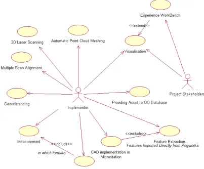
[image:8.595.95.499.314.648.2]Use cases were developed as outlines of the 3D laser scanning system before delving into the details. The laser scanner system was described as a high level package use cases, which are considered architecturally significant. The detail descriptions of the use cases were done in the flow of events. In this activity, the use cases were used for the conceptual modelling of what the system should do from the user’s point of view. Thus, use cases act as the common language for communication between the stakeholders. The Use case diagram below (Figure 2) further elaborates the interaction and integration of the laser scanning systems with the other systems within the INTELCITIES scope.
Figure 2: Use case Diagram for the conceptual modelling of the 3D Laser scanning system.
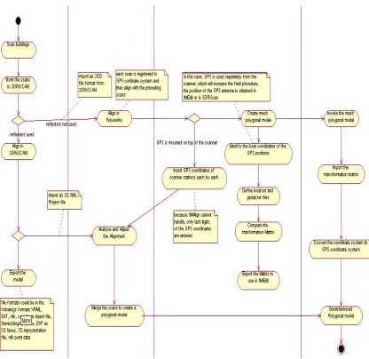
Figure 3: the Activity diagram indicates the flow of events for the 3D laser scanning and georeferencing use cases.
5 Limitations and Lessons Learnt
Since the INTELCITIES project started in February 2004, only 3 package level use cases were concentrated on in regard to the integration, which are 3D printing system, GPS system and CAD system.
information accurately and fast from non-meaningful data such as feature lines for 2D and 3D CAD plans and models. Otherwise, use of the post-processed model of the laser scanning system is not easy to handle for the other systems.
In the following subsections the specific limitations are described.
5.1 Limitations in integration with the GPS system
The GPS integration can be done in either 3DRiSCAN software, which is for data capture and manipulation of the laser scanner or Polyworks software, which is for 3D modelling and editing the mesh polygonal models and providing outputs in the required formats for the other systems.
In regard to georeferencing in the 3D RiSCAN software, the followings are the limitations encountered.
1) If the GPS system is mounted on top of the scanner to georeference the scanner position in WGS coordinate system, the orientation to the north is not reliable and the scanner finishes its work far quicker than the GPS system, the GPS system slows down the field work significantly
2) If the GPS system runs separately at the same time with the laser scanner in the same field concurrently, the georeferencing can be done in two ways:
a. all of the individual scans are registered in the project coordinate system and then convert it into global (GPS) coordinate system in the office b. all of the individual scans can be registered directly to global (GPS)
coordinate system
However, in either case, the model will be problematic in importing into Polywork software for precise alignment and adjustment, merging for the creating polygonal mesh model, and editing because the number of digits of coordinates in the global (GPS) coordinate system is more than the number of digits that the Polywork software can handle. That is to say, the Polywork software can handle up to 6 digits whereas in the global (GPS) coordinate system there are 9 digits.
In regard to georeferencing in Polywork modeller using the IMAlign and IMEdit features, the followings are the limitations encountered.
1) If GPS is mounted on top of the scanner, the georeferencing can be done in IMAlign module of the Polywork software using the manual alignment and constraint alignment features. However, IMAlign module cannot handle 9 digits of global (GPS) coordinates. Therefore, only last 6 digits of global (GPS) coordinates are imported. In addition, using the GPS mounted on top of the scanner slows down the field work.
handle upto six digits for the global (GPS) coordinates also incurs in this approach.
5.2 Limitations in integration with the CAD systems
The laser scanner system enables to produce a polygonal mesh model of the existing buildings and provides export facilities in various CAD oriented data formats. However, this model is not directly useful for developing the 2D and 3D CAD models, which is aimed at using for building refurbishment process. This is because the polygonal model is formed by a large number of triangles, which needs extracting the features lines for CAD modelling.
However, it is not sufficiently accurate to extract the feature lines using the cross-sections and curves, which do not provide straight lines as an output. There is not yet fast, fully automated and accurate process is identified for the extraction of feature lines. Cross sectioning can be considered for extraction of 2D bird-eye view CAD plans using a mode of indoor scans. However, it is not sufficient for an ideal bird-eye view CAD plan because wall thickness cannot be obtained accurately unless reflectors are used during the scanning process.
In order for fully automated and accurate extraction of feature lines for CAD modelling, a specific approach is identified, which includes use of planes and cross-sections. In the approach, the planes are inserted through each surface in the model. All the vertices deviated from the plane are projected to the plane, which result in a very smooth surface before cross-sectioning. This activity is applied to every surface, when this activity completed, cross-sections are applied through the same planes to each surface. All cross-sections are exported in dxf or IGES formats for analysis in CAD software such as Microstation. The output in Microsation will be a 2D or 3D CAD models with straight lines.
However, this approach requires long time for editing in the Polyworks software and currently it is investigated to reduce the editing period by improving the quality of the models during the process.
5.3 Limitations in Integration with the 3D Printing System
The 3D printing system only accepts files in STL format and it uses wax and plastic to make the shape of the model. Therefore, the model should be closed shape or the surfaces should have thickness for a complete and accurate printing.
model. However, exporting the extruded model from Microstation sometimes is not sufficient because the STL export of the extruded model has irrelevant holes in the model, which makes the model incomplete for 3D printing. This is attributable to the arbitrary triangles make up the model.
6 Future Work
Apart from the integration with GPS, all the rest of the integrations, to some extent, rely on the success of producing 2D and 3D CAD models. In other words, the
success in the extracting the required meaningful information from the 3D polygonal model developed in the laser scanning system.
Despite the limitations raised in the previous section, using the approach of the plane insertion and projecting the vertices on the plane and cross sectioning through the planes, a 3D CAD extraction has been achieved, which has walls, stairs, columns, doors as opposed to triangles in the 3D model produced in the laser scanning system. The future activity regarding CAD extraction will be improved the speed and quality of the process.
Indoors scanning will be implemented using the reflectors during the field work for developing the CAD plans with accurately defined wall thickness. Furthermore, the use of a camera with the scanner together for object texturing will be taken into consideration to facilitate the post-processing.
In regard to integration with the GIS system, the achievement explained in the previous paragraph will ease the integration with the GIS system. The commercial GIS system is in fact not compatible with 3 dimensional data. However, a recent research completed in the University of Salford enables the integration of GIS and VR. However, VR models, which are in fact 3D building blocks, needs improvement through representing the building elements such as windows, doors, wall, etc, for better beneficiary for urban planning and local governments. The idea is to use the 3D and 2D CAD models derived from the 3D laser scanning system in order to improve the quality of VR model, which will be integrated with the GIS system.
The approach can be the way forward for defining the building elements in IFC [7] (Industry Foundation Classes) common data exchange format and store this information in the nD modelling repository.
7 Conclusion
technology is drawn up and the limitations and lessons learnt since the project started have been explained. Lastly, future work and vision is summarised.
References
[1] Hamilton, A., Trodd, N., Zhang, H., Fernando, T., Watson, K., “Learning through Visual Systems to Enhance the Urban Planning Process”, Journal of Environment and Planning B: Planning and Design 28(6) 833-845 Pion Ltd. London, 2001.
[2] Schofield, W., “Engineering Surveying 5th Edition: Theory and Examination Problems for Students”, 2001.
[3] Erikson, H., Penker, M., “Business Modelling with UML: Business Patterns at Work”. OMG Press, John Wileys & Sons, 2000.
[4] Polywork User Guide
[5] Arayici, Y., Hamilton, A., Hunter, G., “Reverse Engineering in Construction”, in “proceedings of The Conference of World of Geomatics 2003: Measuring, Mapping, and Managing”, Telford, UK, 2003.
[6]