Design Investigation of Three Phase HEFSM with
Outer-Rotor Configuration
Abstract — Flux switching machines (FSMs) with the advantages of single piece of rotor and robust rotor structure become a popular research topic in recent years that suitable for various speed conditions. This machine combined the advantages of Switched Reluctance Machines (SRMs) and Permanent Magnet Synchronous Machines (PMSMs). Previously, most of developed FSMs are mainly focused on inner-rotor configuration, and hard to find research on outer-rotor FSM configuration. Therefore, this paper presents design investigation of three phase Hybrid Excitation Flux Switching Machine (HEFSM) with outer-rotor configuration. Primarily, design processes of the outer-rotor HEFSM especially for drawing parts, materials and conditions used, and properties setting are described in detail. Next, coil arrangement tests are also evaluated to confirm the principle operation of the machine and the phase sequence of each armature coil. Finally, DC field excitation flux capabilities at various current density condition, flux path and flux distribution, back-emf voltage and initial torque are also investigated.
Keywords: Flux switching machine; Hybrid field excitation; outer-rotor configuration
I. INTRODUCTION
Nowadays, research and development of Flux Switching Machines (FSMs) with advantages of single piece and robust rotor structure that suitable for various performances and applications has become more popular. The FSM was first
introduced in the mid of 1950’s and well known as single -phase generator or alternator [1]. Obviously, since ten years ago, many novel and new topologies of FSMs have been established and enriched for better performances applied in various applications such as in wind power generator, automotive system, aerospace, traction drive as well as in low cost domestic appliances [2-5]. There are three categories of FSMs known as permanent magnet (PM) FSMs, hybrid excitation (HE) FSMs, and field excitation (FE) FSMs. For PMFSMs and FEFSMs, they have only either PM or DC excitation coil as their main flux sources, whereas for the HEFSMs, it combines both PM and DC excitation coil on the stator to generate fluxes [6].
In conventional PM brushless machines, the PM is placed on the rotor, while the armature coil is put on the stator. As well known, when PM is placed on the rotor, it usually exhibits eddy current loss and cause to rise up the temperature of the
PM make it hard to release the generated heat on the rotor. Since, for the FSMs all the active parts namely PM, FEC, and armature coil are located on the stator, the temperature rise may be more easily managed [7-8].
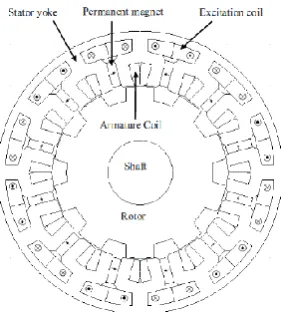
[image:1.595.362.503.540.696.2]Among several categories of FSMs, most development and improvement have been made are focused on PMFSM due to their high torque and power density. With both PM and armature windings located on the stator and robust rotor structure, the machine inherits a switched reluctance machine (SRM). Moreover, the machines have better suitability for high speed applications [9-10]. However, the generated flux of the machine is uncontrollable due to constant PM used as a main flux source. Therefore, HEFSM that consist of two flux sources of PM and DC FEC has been introduced in 2007 to provide variable flux control capabilities [11]. Thus, with the improvement have been made, the machine has additional advantage of suitability for low and high speed applications. The original structure of HEFSM is shown in Fig. 1. Nevertheless, previous research and development of HEFSMs have focused on inner-rotor configuration, and hard to find researches on outer-rotor HEFSM. According to the developed machine of PMFSM with outer-rotor configuration, the machine can provide higher torque and power density and increase it efficiency [12]-[13]. Therefore, this paper presents a design investigation of three phase outer-rotor HEFSM to meet the target performances.
Fig. 1 Original structure of HEFSM
M.Z. Ahmad is with Universiti Tun Hussein Onn Malaysia, Johor, 86400
1
M. Z. Ahmad,
2E. Sulaiman, and
3M. Jenal,
4W. M. Utomo,
5S. A. Zulkifli, and
6A. Abu Bakar
Electrical Power Engineering Department Faculty of Electrical & Electronic Engineering
Universiti Tun Hussein Onn Malaysia Johor, Malaysia
In this study, the paper is structured as follows. Section II describes the operating principle of outer-rotor HEFSM, while the machine design methodology is discussed in Section III. The results of armature coil arrangement test, flux path and flux distribution, back-emf characteristic and initial torque at various current density are demonstrated in Section IV. Finally, a conclusion is presented in Section V.
II. OPERATING PRINCIPLES OF OUTER-ROTOR HEFSM The concept of “flux switching” has been introduced in FSMs is based on the changing of flux linkage’s polarity according to the movement of salient pole rotor. In the case of PMFSM, the PM itself is act as the main flux source, whereas for the HEFSM, there is an additional DC FEC to generate more fluxes. However, the entire active parts namely PM, armature coils and DC field windings for both design are located on the stator with PM or DC FEC and armature coil placed in alternate stator teeth. Concurrently it provides robust rotor structure and appropriate for high speed applications. Moreover, the HEFSM has additional advantages of flux control capabilities due to the existence of DC FEC. Thus, the appropriate pole numbers of rotor and slot numbers of stator for the proposed outer-rotor HEFSM can be examined using equation (1).
q k N
Nr s
2
1 (1)
where Nr is the number of rotor poles, Ns is the number of
stator slots, k is the integer number, and q is the number of phases. In this study, the selected rotor pole number and stator slot number is 10 and 12, respectively and q is set to 3 making a three phase motor.
In this proposed motor, the flux linkage of armature coil has one periodic cycle in each 1/10 revolution. Hence, the frequency of induced voltage observed on the armature coil is ten times of the mechanical rotational frequency. Therefore, the relationship of electrical frequency, fe to mechanical rotation
frequency, fm for the FSMs can be written as,
fe = Nr
.
fm (2)where fe is the electrical frequency, fm is the mechanical
rotational frequency and Nr is the number of rotor poles
respectively.
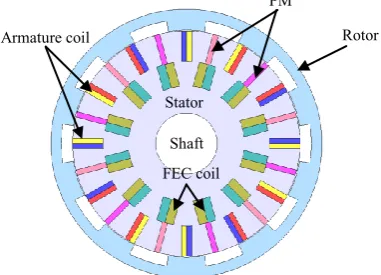
The explanation of the principle operation of the proposed outer-rotor HEFSM can be referred to Fig. 2. With the motor consist of single piece of rotor that similar to SRM, in this proposed motor the rotor is shown in the upper part, while the stator that consists of PMs, FECs, and armature coils are located in the lower part of Fig. 2. The term “hybrid excitation
flux” is created due to PM and DC FEC is placed between two stator poles. Figs. 2(a) and (b) demonstrate the generated flux from PM in red line and flux from DC FEC with blue color flow in the same direction. The fluxes flow from the inner stator into the outer-rotor and return back through the next rotor pole to the next stator teeth to complete one flux cycle.
Furthermore, if the machine produces more excitations fluxes by combined the flux from PM and DC FEC as shown
[image:2.595.322.538.49.234.2]
Fig. 2 Operating principle of ORHEFSM (a) θe= 0º (b) θe = 180º higher
excitation, (c) θe= 0º (b) θe = 180º less excitation
in Fig. 2(a) and (b), higher torque will be obtained. Hence, when the rotor starts rotating and moves to the right, the rotor pole will allocate on the next stator tooth. This will cause the magnitude and polarities of the flux linkage changed their direction. Thus, the magnetic flux generated by PM and DC FEC is only changes their direction towards the armature coil slot and not rotate as movement of the rotor. When the winding configuration of DC FECs are set as shown in Fig. 2(c) and (d), the total flux flow from the stator into the rotor and return back from the rotor to the stator is only come from PM, whereas the flux generated from FEC is only circulating on its particular winding slots. Consequently, due to less of excitation flux established, the machine will produce low output torque.
III. DESIGN METHODOLOGY OF THE PROPOSED OUTER -ROTOR HEFSM
In this paper, design investigation of three-phase outer-rotor HEFSM with 12S-10P configuration is implemented in which the initial 2-dimensional (2-D) structure of outer-rotor HEFSM configurations and dimensions are illustrated in Fig. 3 and Table I, respectively. The proposed machine has very simple structure where all the components slots are in rectangle shape and all coils are in concentrated winding. From the structure, it is clear that the outer-rotor HEFSM has 24 stator teeth, 10 rotor poles with alternate DC FEC, PM and armature coil slot around the stator. Initially, the DC FEC is wound alternately in counter-clockwise and clockwise polarity, while all the three-
(a)
(c)
(b)
(d)
Fig. 3 The initial design structure of outer-rotor HEFSM Stator
Shaft
PM
Armature coil Rotor
[image:2.595.332.523.567.704.2]phase armature coils are wound in counter-clockwise direction. In addition, it is expected that the machine offers non-overlap winding between the DC FEC and armature coil to provide shorter end winding and hence contribute to reduce copper loss effect.
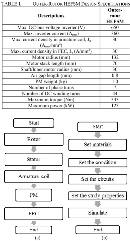
In this design study, the 2D- FEA solver used is JMAG-Designer ver.12.1 and firstly, JMAG Editor is used to draw the rotor, stator, PM, DC FEC, and armature coil. Once, the machine design has completed in JMAG Editor, the file is essential to be uploaded into JMAG Designer to set the materials, conditions, circuit’s configuration and properties of each component on the machine. The design process of drawing part and condition setting are demonstrated in Fig. 4. Furthermore, coil arrangement tests are conducted to validate the principle operation of outer-rotor HEFSM and to set the appropriate position and polarity of each armature coil phase. Then, the flux linkages, flux distributions at zero rotor position, and induced voltage at various DC FEC current densities, Je are
analyzed and compared. Finally, the torque at various DC FEC current densities, Je of outer-rotor HEFSM is also investigated.
In this paper, the parameters of the proposed design machine from D1 to D10 are demonstrated in Table II and Fig. 5,
respectively.
Initially, several assumptions have been made on the design of each 30º mechanical angle of stator yoke and described as follows; (i) The inner radius of the motor is set to 30 mm for
the motor’s shaft while the outer radius is set to 110.6 mm,
making the stator depth of 80.6 mm which is 61% of 132 mm motor radius and within the range of general machine split ratio, (ii) The PM volume of the proposed machine has been reduced and set to 1.0 kg compared with the PM used in IPMSM. The reason is to reduce the PM cost due to the increasing price of PM since 2011, (iii) Generally, it is expected that the longer the PM depth will produce more flux and enhance the overall performances, therefore in this design the PM depth is set approximately one third of the stator depth. However, demagnetization effect on the PM edge needs to be taken into consideration when higher PM depth is applied, (iv) The slot area of DC FEC is set to 197.01 mm2 to give a maximum current density, Je of 30 A/mm2 with 44 turns of
FEC winding. The FEC slot depth is less than the PM depth to give an appropriate distance between the adjacent FEC slots area for the flux to flow in this area, (v) The depth of armature slot area is set similar to the PM depth in order to avoid overlapping between armature coil winding and FEC winding. Therefore, it is expected that the motor will use shorter coil end winding and so reduces copper loss effect.
[image:3.595.326.536.64.451.2]Besides that, the initial for 36º mechanical angle of rotor iron is designed with several expectations; (i) The distance of air gap is maintained at 0.8 mm as in IPMSM, hence the inner rotor radius becomes 111.4 mm and this gives a rotor depth of 20.6 mm, (ii) The depth of the rotor pole is set to 10.3 mm that consume half of the rotor iron depth to allow the flux flow easily through the outer rotor pitch, (iii) The rotor pole arc width is set to be similar with the rotor pole gap to allow optimal flux flows into the rotor pitch.
TABLE I. OUTER-ROTOR HEFSMDESIGN SPECIFICATIONS
Descriptions
Outer-rotor HEFSM Max. DC-bus voltage inverter (V) 650
Max. inverter current (Arms) 360
Max. current density in armature coil, Ja
(Arms/mm2)
30
Max. current density in FEC, Je (A/mm2) 30
Motor radius (mm) 132
Motor stack length (mm) 70 Shaft/Inner motor radius (mm) 30 Air gap length (mm) 0.8
PM weight (kg) 1.0
Number of phase turns 7 Number of DC winding turns 44
Maximum torque (Nm) 333
Maximum power (kW) 123
Fig. 4 Design methodology of the proposed outer-rotor HEFSM (a) Parts drawing (b) Conditions setting
TABLE II. THE DESIGN PARAMETERS FOR THE PROPOSED ORHEFSM Parameter Description Initial
D1 Rotor inner radius (mm) 110.6
D2 Rotor pole depth (mm) 10.3
D3 Rotor pole arc width (o) 9
D4 Distance between airgap and PM (mm) 0.2
D5 PM depth (mm) 30
D6 PM width (mm) 2.63
D7 FEC slot depth (mm) 23.88
D8 FEC slot width (mm) 8.25
D9 Armature coil slot depth (mm) 29.7
D10 Armature coil slot width (mm) 4.95
[image:3.595.324.537.504.641.2]
IV. INITIAL PERFORMANCES BASED ON 2-DFEA
A. Armature Coil Arrangement Test
Initially, the operating principle of the outer-rotor HEFSM is essential to be performed by implementing coil arrangement tests on each of armature coil. The purpose is to identify and set the polarity of each armature coil phase. With the DC field excitation current density, Je set to 0 A/mm2 in which the flux
source is only come from PM, the flux linkages at each armature coil are observed. Then, the generated flux at each of armature coil are compared and according to 120º phase shifted of normal three-phase system, a three-phase of 12 armature coils are examined. The three-phase flux linkage of the proposed machine is demonstrated in Fig. 6. It is clearly seen that, all the flux linkages are almost purely sinusoidal with the maximum flux of 0.014 Wb. As a result, the principle operation of the proposed machine has been proved through coil arrangement test and the three-phase armature coil has successfully achieved.
Furthermore, flux linkage characteristics at various DC FEC current densities, Je are investigated. The U-phase flux
linkage with Je set from 0 A/mm2 to 30 A/mm2 is illustrated in
Fig. 7. It shows that the magnitude of flux linkage is increase when Je is varied from 0 A/mm2 to 15 A/mm2 and then start to
reduce when Je is further increased up to maximum DC FEC
current density of 30 A/mm2. The maximum flux linkage has been obtained at DC FEC current density of 15 A/mm2 with
the magnitude of 0.042 Wb. The decrement of flux linkage just after Je set to 15 A/mm2 need to be investigated in order to
get higher magnitude of flux linkage and torque.
B. Flux Path and Flux Distribution
[image:4.595.42.284.51.161.2]The flux path at various rotor positions in open circuit condition and flux distribution at load condition is
Fig. 6 Three-phase flux linkage of the proposed machine
Fig. 7 U-phase flux linkage at various DC FEC current density
demonstrated in Fig. 8 and Fig. 9, respectively. From Fig. 8, it is clear that almost 50% of flux lines are flow from stator to rotor and return through the nearest rotor pole to make a complete flux cycle and it is expected produces high induced voltage in no load condition.
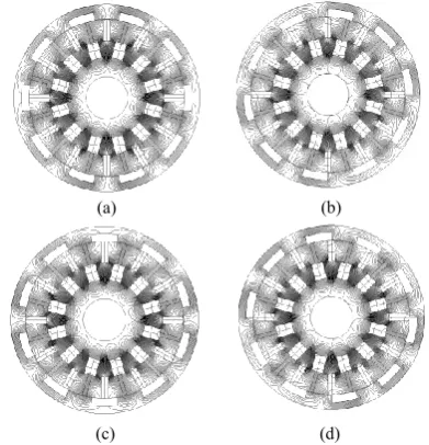
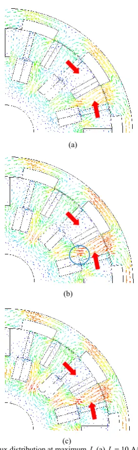
Furthermore, the flux distribution is also investigated to monitor field saturation effect on the machine. The investigation is implemented on three conditions of FEC current density, Je which are set at 10 A/mm2, 20 A/mm2, and
30 A/mm2. The armature coil current density is kept constant
at maximum of 30 Arms/mm2. From the investigation at low
FEC current density of 10 A/mm2, it is observed that the flux
flows smoothly as shown in Fig. 9(a). It’s confirmed that the flow of the flux meet their principles of magnetic flux direction. Nevertheless, when the field excitation current density is increased to 20 A/mm2, it is observed that the flux
[image:4.595.327.539.53.169.2]flow in outward direction as circled with blue color in Fig. 9(b) start to saturate. This phenomenon occurs due to higher magnetic flux generated from FEC has combined with the magnetics flux of armature coil. Moreover, when the field excitation current density increased to 30 A/mm2, the flow of magnetic flux in outward direction is totally saturated as shown in Fig. 9(c). Therefore, the distance between the nearest two FEC slots and the space between the lower edge of armature coil slot and upper edge of FEC slot
Fig. 8 Flux path of outer-rotor HEFSM (a) 0º rotor position, (b) 9º rotor position, (c) 18º rotor position, (d) 27º rotor position D1
D2 D3
D5 D6
D7 D8
D9 D10
D4
Fig. 5 Design parameters defined as D1– D10
(a) (b)
[image:4.595.335.531.491.694.2] [image:4.595.57.271.578.694.2]has possibility to be adjusted to diminish the flux saturation effect.
C. Back-emf in Open Circuit Condition
Further investigation of the proposed machine on the back electromagnetic force (back-emf) in no load condition is implemented at the speed of 3000 rpm. The results obtain for back-emf at various FEC current density conditions are plotted in Fig. 10. It is obvious that the back-emf with the amplitude of only 29.94 V has obtained when the flux source is only come from PM. Hence, when the secondary flux source is applied with the current density of 15 A/mm2, the amplitude of
[image:5.595.323.543.64.209.2]the back-emf is increased drastically to 270.12 V and much distorted. The main reason of this condition is due to the strengthening effect of the flux from secondary flux source
Fig. 9 Flux distribution at maximum Ja (a) Je = 10 A/mm2 , (b) Je = 20 A/mm2 , (c) J
e = 30 A/mm2
Fig. 10 Back-emf at 3000 r/min
itself. When Je set to maximum of 30 A/mm2, the amplitude of
back-emf has reduced back to 159.59 V with less of harmonics.
D. Torque Characteristics at Various Armature Current
Density
The torque characteristics against field excitation current density, Je at different armature current densities, Ja are
demonstrated in Fig. 11. The graph presents that the incremental of field excitation current density, Je will raise the
torque up to certain amount of injected Je into the system. At
low armature current density of 5 Arms/mm2, the torque
increased until DC FEC current density of 10 A/mm2 and start
to reduce when higher Je is applied. Similarly, the same
phenomenon occurs at the rest of armature coil current density up to maximum where the torque start to reduce at Je of 12
A/mm2, 15 A/mm2, 20 A/mm2, 22 A/mm2, and 25 A/mm2,
respectively. The highest torque of 192.29 Nm has been examined when Je is set at 25 A/mm2 with the power of 95.19
[image:5.595.85.227.236.698.2]kW. Since, both torque and power generated of the proposed machine still not achieve the target performances, design improvement and optimization will be conducted in future.
Fig. 11 Torque vs Je at various Ja
V. CONCLUSION
In this paper, design investigation of three phase hybrid excitation of flux switching machine with outer-rotor configuration has been presented. The proposed machine has simple structure where all the components involve are in rectangular shape and easy to manufacture. The coil (a)
(b)
[image:5.595.323.541.492.613.2]arrangement test has been conducted using 2-D JMAG-Designer software to authenticate the appropriate phase of each armature coil and confirm the principle operation of initial design motor. From the results that have been obtained, the initial performances of the proposed motor have ability to be further enhanced by conducting design optimization.
REFERENCES
[1] S. E. Rauch and L. J. Johnson, “Design principles of flux switch altenators,” AIEE Trans., vol 74III, no. 12, pp. 1261-1269, 1955. [2] E. Sulaiman, M.F.M Teridi, Z.A. Husin, M.Z. Ahmad, and T.Kosaka,
“Performance comparison of 24S-10P and 24S-14P field excitation flux switching machine with single DC-coil polarity”, Proc. of 7th
IEEE International Power Engineering and Optimization Conference
(PEOCO), pp. 46-51, 2013.
[3] Y. Amara, E. Hoang, M. Gabsi, and M. Lecrivain: “Design and comparison of different flux-switching synchronous machines for an aircraft oil breather application”, Euro. Trans. Electr. Power, no. 15, pp. 497-511, 2005.
[4] W. Hua, M. Cheng, and G. Zhang: “A novel hybrid excitation flux -switching motor for hybrid vehicles”, IEEE Trans. Magn., vol. 45, no. 10, pp. 4728-4731, Dec. 2009.
[5] C. Pollock, H. Pollock, R. Barron, J. R. Coles, D. Moule, A. Court, and R. Sutton: “Flux-switching motors for automotive applications”,
IEEE Trans. Ind. Appl., vol. 42, no. 5, pp. 1177-1184, 2006. [6] E. Sulaiman, T. Kosaka, and N. Matsui: “High power density design
of 6slot-8pole hybrid excitation flux switching machine for hybrid
electric vehicles”, IEEE Trans. on Magn., vol.47, no.10 pp. 4453-4456, Oct. 2011.
[7] Z. Q. Zhu, Y. Pang, D. Howe, S. Iwasaki, R. Deodhar, and A. Pride, “Analysis of electronic performance of flux-switching PM machines by non-linear adaptive lump parameter magnetic circuit model”,
IEEE Trans. on Magn., vol. 41, no. 11, pp. 4277-4287, Nov, 2005. [8] E. Sulaiman, T. Kosaka, N. Matsui, and M. Z. Ahmad, “Design
improvement and performance analysis of 12Slot-10Pole permanent magnet flux switching machine with field excitation coils”, Proc. of IEEE Int. Power Engineering and Optimization Conference, Shah Alam, pp 202-207, 2011.
[9] J. T. Chen, Z. Q. Zhu, ans D. Howe, “Stator and rotor pole combinations for multi-tooth flux-switching permanent-magnet brushless AC machines”, IEEE Trans. on Magnetics, vol. 44, no. 12, pp.4659-4667, 2008.
[10] Z. Q. Zhu, and J. T. Chen, “Advanced flux-switching permanent magnet brushless,” IEEE Trans. on Magnetics”, vol. 46, no. 6,pp1117-1453, pp. 1447-1453, June 2010.
[11] E. Hoang, M. Lecrivain, and M. Gabsi, “A New Structure of a Switching Flux Synchronous Polyphased Machine,” in European Conference on Power Electronics and Applications, no. 33, pp. 1–8, 2007.
[12] W. Fei, P. Chi, K. Luk and J. S. Y. Wang, “A Novel Outer-Rotor Permanent-Magnet Flux-Switching Machine for Urban Electric Vehicle Propulsion,” in 3rd International Conference on Power Electronics Systems and Applications (PESA), pp. 1–6, 2009. [13] W. Fei, P. Chi, K. Luk, S. Member, J. X. Shen, Y. Wang, and M. Jin,