International Journal of Emerging Technology and Advanced Engineering
Website: www.ijetae.com (ISSN 2250-2459,ISO 9001:2008 Certified Journal, Volume 3, Issue 5, May 2013)
453
Design of an Automatic Solar Tracking System to Maximize
Energy Extraction
Mostefa Ghassoul
Department of Chemical Engineering, College of Engineering, University of Bahrain Abstract-- This paper presents the design of a solar
tracking system driven by a mnicrochip PIC 18F452 micro controller. The system is based on two mechanisms. The first one is the search mechanism (PILOT) which locates the position of the sun. The second mechanism(intelligent PANELS) aligns itself with the PILOT only if maximum energy possible could be extracted. On top of that the main advantage of the technique is that the rotation only takes place, if the energy obtained in the new position is higher then that consumed by the panels during the transition. So there are two mechanisms, one for the search which is mounted on a miniature motor and consumes only small amount of energy. Its role is to locate the best position for maximum energy extraction. The second one is the panels mechanism which rotates to the position when energy extraction is optimal.
Keywords-- Panels, PILOT, PIC micro controller, LDR, sunrise, sunset.
I. INTRODUCTION
For the last few decades, researchers have been concentrating on developing clean, renewable energy resources, and certainly will be in the near future, to replace carbon based energy resources such as oil, gas and coal. This is due two main reasons. One is that most of carbon based energy will dry up within the next fifty years at most, and secondly, carbon based energy is responsible for the green house emission problem which has hit the world in the last decade (This has become known as gas emission or global warming), from Americas, Europe and recently has reached Asia and will certainly reach Africa if nothing has been done to address the problem. One of the renewable energies of interest is solar energy, especially in region where sun shining is of abundance like ours. Lot of research has been carried out in improving solar cells efficiency. This has been encouraged by the improvement of the cells efficiency where it was merely 17% in the early 90‟s to pass the 33% mark lately. But, unfortunately, it is still suffering from few draw backs. The first one is the relatively high cost of the cells. The second one is that the efficiency is still low even at the current rate of 33%.The third one is the positioning of the solar cells, especially during the long summer days where the sun shines for more than 16 hours a day and fixed cells do not extract maximum energy. In the past, people using solar energy fix the panels mid way between the geographical east and west with approximately 30 degrees towards the south.
Studies have shown that this is not ideal positioning in order to maximize energy extraction. A better way is to orient the panels continuously towards the sun, using single axis or double axes. Many researchers have published papers on the subject. In single axis system was designed. Hession & al.(1984) designed a sun tracker where the sun position is sensed using photo
transistors connected to a 2.34-m2 cylindrical parabolic
collector mounted on a simple structure. Clifford & al. (2004) designed a solar tracker in the equatorial region, and they reported that computer modeling predicts an increase of 23% in efficiency compared to fixed panels. Huang & al. (2011) developed a 1 axis 3 position sun tracking PV to measure the daily and term power generation of the solar PV system. Chin & AL. (2011) designed a compact solar tracker mounted on a wall. This system was operated at different modes to accommodate for weather conditions. To increase still the efficiency of energy extraction, many two axes systems were developed. Al-Soud and co. (2010) have designed a parabolic solar cooker using two axes tracking system. They showed that the temperature inside the heating tube, reached 90 degrees Celsius. Even better, Abu-Malouh & co. (2011) reported that they constructed a solar cooking system, with a dish built to concentrate solar radiation on a pan that was fixed at the focus of the dish and they showed that the temperature inside the pan reached 93 degree Celsius. Batayneh & co. (2012) followed different approach by designing a fuzzy based two axes tracking system. Though, the system looks to be promising from simulation point of view, it needs to be tested experimentally. several algorithms were developed.
II. BACKGROUND
International Journal of Emerging Technology and Advanced Engineering
Website: www.ijetae.com (ISSN 2250-2459,ISO 9001:2008 Certified Journal, Volume 3, Issue 5, May 2013)
454
To improve the system, a better scheme was designed (M.Ghassoul (2009) and M.Ghassoul (2010)).The scheme is designed around two sub-systems. The first sub-system is for detecting the position where maximum energy could be extracted and is known as the PILOT, and a second sub-system is made up of the solar panels with the control strategy and is known as panels. This scheme presents an optimal positioning mechanism of the panels so that maximum energy is extracted regardless of the weather conditions and the length of the day. The position is determined by using a search technique, based on a PILOT scheme. The PILOT is built around a small sensor mounted on a miniature electric motor, which only consumes a very tiny amount of energy. The aim of the PILOT is to move to the new angle, and picks up the voltage induced. That voltage is compared with that sensed by the sensor mounted on the panels. If the PILOT voltage is bigger than that of the panels by a predetermined offset, then the panels move and align themselves with the PILOT, otherwise they stay in their current position. This scheme suffers from a major drawback; that is the alignment procedure used(M.Ghassoul(2010)). The procedure was based on counting the number of missed pulses then generating a pulse equivalent to the missed pulses to drive the panels through. Due to natural phenomena such as friction, and load variation, the speed by which rotate the panels could slightly vary and this results in the miss-alignment between the PILOT and the panels. On top of that the creation of this total driving pulse has lead to the introduction of extra software which has resulted in missing sometimes of some pulses due to the fact the loading of time constant into the low and high timer registers of the microcontroller results into missing about fifteen pulses not counted. Adding to that the two extra timers resulted in continuous configuration of the latter, one time configured in producing the pulses which drives the PILOT and another time, configured to drive the panels. This has lead to a time lag which is not easy to compensate depending on the variation of the missed unpredictable pulses due to the variation of the weather. Adding to this, when the sky gets unpredictably cloudy especially in winter, the sensor tends to sense lower energy than expected. The solution to this problem is the subject of the current paper. That is by replacing the software procedure by a much simpler alternative hardware one. This is done by mounting a proximity switch onto the panels and a reflector on the PILOT. When the PILOT moves to the new position, the voltage difference between the voltage detected by the PILOT sensor and that detected by the panel sensor is greater than the threshold then the panels rotate forward to align themselves with the PILOT.
That happens when the panels come close to the proximity of the reflector mounted on the PILOT (about 3 mm), the proximity switch closes. This latter activates the input of the microcontroller; and as a result, the controller drives the panels to standstill. Thus the panels always follow the PILOT regardless of the load , weather conditions, friction as well as the software problem where duration adaptation was needed all the time with the old design. The system waits for the next pulse, and the procedure repeats itself during the whole trajectory. When the end run proximity switch is activated, the system comes to a standstill and waits for the sun to set for the system to roll back to the original position and the procedure repeats itself the following day. The tracking system is designed around a PIC 18F452 microcontroller. The choice of this type of controller is due to the fact that it is cost effective, easily programmable, and has many features such as the analogue to digital conversion, comparison as well as timers and counters required for the operation. It could also be erased and reprogrammed online using the In-Circuit Serial Programming technique (ICSP).
III. SYSTEM DESIGN
International Journal of Emerging Technology and Advanced Engineering
Website: www.ijetae.com (ISSN 2250-2459,ISO 9001:2008 Certified Journal, Volume 3, Issue 5, May 2013)
455
In the case of hardware, which is the case here, the two voltages are compared through a hardware comparator, and the output is used to trigger the controller accordingly).If the panel voltage is less than that of the PILOT by the predetermined threshold (this is set through a variable resistor), then the panels start moving to align themselves with the PILOT until the proximity switch is activated when it comes close to the reflector mounted on the PILOT. If this condition is not met, then the system moves to the next scan ( Figure (2) shows the design of the new system). This procedure repeats itself with each PILOT movement until one of the following conditions is met. Either the end proximity switch is activated or the sun sets, activating the PILOT LDR. In the first case, the proximity switch( known as evening proximity switch) is activated where the PILOT is oriented towards the west (sunset). During longer days of the year, it makes sure that the panels do not over run their trajectory and a misalignment takes place, so that the PILOT and the panels will no longer be facing the sun. If this is the case both panels and PILOT stop and wait for the sun to set which is detected by the LDR. On sun set, the system rotates all the way back to the starting position. When the start proximity switch is activated, the system comes to a halt (facing geographical east) and waits for the sun rise for next day to repeat the procedure (This is basically triggered through a software RS flip flop with reset priority, where the flip flop is set when end run proximity switch is activated and sun sets, and is reset when the start proximity switch is activated).
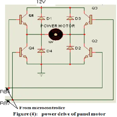
IV. MOTOR DRIVE
International Journal of Emerging Technology and Advanced Engineering
Website: www.ijetae.com (ISSN 2250-2459,ISO 9001:2008 Certified Journal, Volume 3, Issue 5, May 2013)
456
V. SUN RISE AND SUN SET DETECTORThe sun rise and sun set detection is straightforward. It is done through a light dependent resistor as shown in figure (5). When sun rises, the LDR resistance decreases and the current through it increases. The voltage at the transistor base builds up until the transistor is forced into saturation. The collector current in turn increases and the coil is energized, and in turn it pulls the relay to close connecting the supply to the micro controller input PORTA pin RA0. When darkness falls, the LDR resistor increases and the transistor base current decreases cutting the collector current, and in turn disconnecting the relay (The flywheel diode is connected to protect the transistor against the di/dt effect). An identical circuit is used for the sun set, with small difference where the input is connected to the micro controller through pin RA3.
VI. VOLTAGE LEVEL DETECTION
The voltage difference between that of the panels and that of the PILOT is detected using the circuit shown in figure (6). The LDR on the right is connected to the panel and the LDR on the left is connected to the PILOT. The two variable resistors are used so that the voltage threshold could be adjusted. When the light intensity on the PILOT‟s cell is bigger than that on the panel‟s cell, the induced current is bigger in the PILOT‟s branch than that in the panel branch; and the voltage at the positive input of the comparator is bigger than the voltage at the negative input; as a result the output of the comparator goes high. This triggers the microcontroller to activate the panel to follow the PILOT as mentioned earlier. If the difference between the two voltages is less than the threshold, then the panels stay in the current position, and the PILOT searches for new position.
[image:4.595.52.240.333.521.2] [image:4.595.363.515.530.676.2]International Journal of Emerging Technology and Advanced Engineering
Website: www.ijetae.com (ISSN 2250-2459,ISO 9001:2008 Certified Journal, Volume 3, Issue 5, May 2013)
457
VII. CHRONOLOGY OF THE SYSTEM
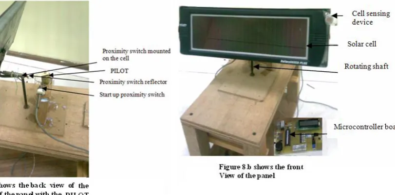
Figure (7) shows the itinerary of the system trajectory during the course of the day. The first pulse shows the correct orientation of the pilot and panels towards the east waiting for sun rise. When the sun rises (sun rise), the PILOT sensor is activated and the PILOT starts rotating at a pulsating rate(say 2seconds on and half an hour off. This is software programmable) as explained earlier. On each falling edge, the comparison process takes place. When the PILOT voltage is smaller than or equal to that of the panels, the required pulses to drive the panels motor are not generated (panels do not follow the PILOT). And when the PILOT voltage is bigger than that of the panels by the programmed offset, the solar panels follow the PILOT until the proximity switch on the panels is activated, they stop, and wait for the next move, until the system hits the end proximity switch, it come to standstill and waits for sun set. When this happens, the system rotates back to the start and waits for the following morning. Figure (8.a) shows the back view of the system, where both sun rise and sun set proximity
switches as well as the tracking proximity switch are located. Figure (8.b) shows the front of the panel as well as the sensing cell. The micro controller board is also shown.
VIII. MICROCONTROLLER PROGRAMMING
As mentioned earlier, PIC18F452 has four timers, timer0 (TMR0), timer1 (TMR1), timer2 (TMR2) and timer3 (TMR(3). In this project, only timer 0 and timer 3 are used ; because they could be programmed either as 8 or 16 bit timers/counters as well as having a programmable pre-scaler to scale down the clock. Timer0 is used to determine the wait duration. That is the time for which the PILOT is standstill, and timer3 is used to determine the time of the rotation. Each timer is associated with a number of special registers. Those registers have to be configured before use. First let‟s see how Timer0 control register is set.
TOPS2-TOPS0 set to 111 to choose 1:256 pre-scaler. PSA set to 0 to assign a pre-scaler to the timer. TOSE set to don‟t care because external clock is not selected. TOCS set to 0 where internal clock is selected. T08BIT set to 0 to configure timer0 as a 16 bit timerTMR0ON set to 1 whenever the timer is turned on. (see figure below extracted from PIC18F452 data sheet).
TMR
0 ON
T08
BIT
T0
CS
TO
SE
PS
A
TO
PS2
TO
PS1
TO
PS0
[image:5.595.119.525.404.605.2]International Journal of Emerging Technology and Advanced Engineering
Website: www.ijetae.com (ISSN 2250-2459,ISO 9001:2008 Certified Journal, Volume 3, Issue 5, May 2013)
458
To derive a 15 second clock from the system clock, a 256 pre-scaler is selected; then the timer is programmed to roll off by 6966 counts. So instead of rolling off from 65536 counts to 00, it is programmed to roll off from (65536-58594 + M + 2 = 6942 +M +2 = 6966) to 00, where M=12 counts which represents the number of cycles between the reading of TMR0L and the writing back to TMR0L. Because the timer register is loaded indirectly, and it requires 12 clocks, during which the timer counter stops; and the added 2 cycles when writing to TMR0L, resets the synchronizer causing the loss of 2 extra cycles. To obtain a 30 minutes delay for instance, the timer is looped 4 times to obtain a full minute, then looped 30 extra times to obtain a full half an hour. After the thirty minutes has elapsed, the PILOT motor is controlled through PORTB, just by setting pin RB3 of PIC18F452, and to bring it to standstill at the end of the step the pin is reset (known as soft latch). The angle by which the PILOT rotates is set through timer3. To obtain a one second pulse, timer3 is used. It rolls off from (65536-59300+12+2 = 6250) to zero to produce half a second pulse and by looping it twice, a full second pulse is obtained. It is worth mentioning here that it would have much better to use two timers in cascade. But unfortunately the PIC18F452 timers could not be cascaded because there is no hardware output pins currently available. As for the panel rotation, when the condition is met, the panel„s motor is activated by setting pin RB6, until its proximity switch comes into proximity of the reflector where it is reset and the panel stops. The procedure then repeats itself.IX.
S
OFTWAREThe program was written using the microchip assembly language and was tested using the MPLAB utility and using the In Circuit Debugger (ICD2).
X. TEST
The prototype is tested in the laboratory using a mobile lamp as a light source, a PILOT and a single panel delivering 24 volts. At the beginning, the prototype is oriented towards the east where the proximity switch (start proximity switch of Omron M8 eight millimeter spacing type mounted on the panel pivot refer to figure (7)) is closed forcing the pin RA3 of micro controller input PORTA to the high state, forcing in its turn the motors (panel and PILOT) to the stand still state. The graph in figure(9) shows the response of the system. When the lamp is turned on, the timer starts and delivers pulses of one millisecond every five minutes interval. The pilot sensor rotates through an angle of approximately twenty degrees for each pulse. Its voltage rises up to approximately 24V. This is shown as black on the graph, so does the panels voltage which is shown as red.
International Journal of Emerging Technology and Advanced Engineering
Website: www.ijetae.com (ISSN 2250-2459,ISO 9001:2008 Certified Journal, Volume 3, Issue 5, May 2013)
459
XI. CONCLUSION
A cost effective intelligent sun tracking system to extract maximum solar energy possible was designed, built and tested. Unlike what was reported into literature, the main advantage of the system is that it is intelligent enough so that the panels only follow the sun if that contributes to extra energy extraction and at the same time, the energy consumed by the panel driving motor is less than that extracted. The system can also align itself to perfection either on sunrise or sunset so no drift is could occur.
Another main advantage is that it takes the days variation during the year into consideration so to make sure that the panels do not lead the sun during longer days nor lag it during shorter ones, neither could it overrun its trajectory during summer longer days. Figure (10) shows the design of the whole circuit. Needless to mention, that a full size crystal oscillator has to be connected to pin 13 of the microcontroller. On top of that, the circuit has to be energized by a 5 volt regulated
voltage. It should be noticed that R4 is added to ensure
that the input to pin RA2 is grounded when the proximity
switch is open. It also should be noticed that the parasite
International Journal of Emerging Technology and Advanced Engineering
Website: www.ijetae.com (ISSN 2250-2459,ISO 9001:2008 Certified Journal, Volume 3, Issue 5, May 2013)
460
REFERENCES[1] P.J. Hession and W.JBonwick, 1984 “Experience with a sun tracker system” Solar Energy, Volume 32, Issue 1, pp 3-11 [2] M.J. Cliford and D. Eastwood, 2004 “ Design of a novel passive
solar tracker” Solar Energy, Volume 77, Issue 3, Sept., PP 269-280
[3] B.J. Huang, ,W.L. Ding and Y.C. Huang, 2011 “Long-term field test of solar PV power generation using one-axis 3-position sun tracker” Solar Energy, Volume 85,Issue 9,Sept., pp 1935-1944 [4] C.S. Chin, A. Babu, and W. McBride, 2011 “Design, modeling
and testing of a standalone single axis active solar tracker using MATLAB/SIMULINK” Renewable Energy, Volume 36,Issue 11, Nov, PP 3075-3090
[5] M.S. Al-Soud, E.Abdulla, A. Akeylah, S. Adallah and E.S.Hrayshat, 2010 “ A parabolic solar cooker with automatic two axes sun tracking system” Applied Energy, Volume 87, Issue 2, Feb., PP 463-470
[6] R. Abu-Malouh, S. Abdallah and L.M. Muslih, 2011 “ Design, construction and operation of spherical solar cooker with automatic sun tracking system” Energy Conversion and Management, Volume 52, Issue 1, Jan., PP 615-620
[7] W. Batayneh, A. Owais and M. Nairoukh, 2013 “ An intelligent fuzzy based tracking controller for a dual-axis solar PV system” Automatic in Construction, Volume 29, Jan., PP 100-106 [8] M. Ghassoul and F. Radwan, " A programmable logic system to
control a solar panel to pump water from a well" 5th IEEE TEM, KFUPM Dhahran, pp 67-70
[9] M. Ghassoul, 2001"Design of PLC based tracking system to maximize solar energy conversion" proceedings of the 8th IEEE TEM, KFUPM Dhahran,17-18 April
[10] M. Ghassoul, 2009 “Design of an intelligent solar tracking system using PIC18F452 micro controller “Conference, International conference on Industrial Electronics, Technology & Automation 2009 Bridgeport University 4-12 Dec
[11] M. Ghassoul, 2010 “ Design of an automatic solar tracking system with the aid of a micro controller “ICASTOR Journal of Engineering, Volume 3, No. 1, January
[12] "28/40 pin 8 bit CMOS flash micro controllers", microchip datasheet 30292, 1998
[13] J. Charais, 2002 "RC model aircraft motor control", publisher J.,microchip technology INC
[14] “Maximum power solar converter” Application AN1211, Microchip Technology, 2008
[15] A. Floricica, 2008 “Low power capacitive sensing with the capacitive sensing module” Application AN1103, Microchip Technology
[16] T. Ferme,2007 “Software handling for capacitive sensing” Microchip Technology
[17] P. Yedamale, 2002 "Speed control of three phase induction motor using PIC 18 micro controller" Microchip Technology INC [18] S.Benling, 1999 " Brush DC servomotor implementation using
PIC 17C756A", Microchip Technology INC
[19] T. Bucella, 1997 "Servo control of a DC brush motor", Teknic INC
[20] E.A. Par, 1996 "Programmable logic controllers" published by Newnes
[21] E. Manlado and Co, 1997 "Programmable logic devices and logic controllers" published by Prentice Hall