REMOTE CONTROL SYSTEM FOR INDUSTRIAL APPLICATION
Shailesh N. Sisat, Vishwajit K. Barbudhe,
Dept. of Electronics & Telecommunication Assistant Professor,
G. H. Raisoni C. O. E. & M., Amravati, Dept. of Electronics & Telecommunication
Maharashtra, India. Jagdambha C.O.E.T, Yawatmal,
Maharashtra, India.
ABSTRACT
There is considerable interest in wireless communication of data in industrial processes. Wireless
sensors, in particular, have the potential to cut up to 90% of the installation costs from many industrial
sensor wiring installations. Reduced cost in wiring installation and wiring maintenance, along with
increased data gathering flexibility are the benefits of wireless sensors. The substantial reductions in
installed cost allow new monitoring and even control capabilities. This paper gives practical approach
about how wireless communication robust enough for industrial plant environment.
KEYWORDS: WSN (wireless sensor network), industrial automat ion, smart ho me, remote
control.
I. INTRODUCTION
Remote control switching application are coming into existence in da y to da y
applicat ion definitely in ho mely applicat ion in industrial applicat io n and many more,
moreover they are very much applicable industrial applicat io n such as remote control light
management dc motor speed management and many more. In nearly eve ry factory floor
and industrial setting, co mmunicat io n links carry vit al informat ion between machinery,
control, and mo nitoring devices. Fro m periodic updates to ongoing process and
manufacturing management, reliable data flow is crit ical to operations. Mu ch o f the
control and status informat ion transferred in industrial setting actuator posit ion,
relat ively litt le bandwidth and connect ion speed a t the other extreme, large file
transmissio n, such as act ivit y logs fro m a production run, re quires mo ving a lot of data
very efficient ly [10].
We must understand the techno logy of wireless co mmunicat ion which is, after all
simply a redio co mmunicat io n link. Radio waves are a fundamental electromagnetic
property o f matter. This property is manifested when an electric current passes through a
metal conductor displacing electrons fro m their orbit s and giving o ff energy. The amo unt
of energy emitted is proportional to the amount of passing current. By passing an
alternat ing current through the conductor, a sinuso idal electromagnet ic wave is
transmitted into space.
Now by considering all o f t hese applicat ions it is possible to develop a new remote
control s ystem, which will be very much helpful in many ho mely applicat ions as per
controlling switchboard by remote, such as to control tube light, fan etc in any house. This
remote control is also useful in agriculture applicat ion as well as in industrial applicat i on.
I. BASIC CONCEPT
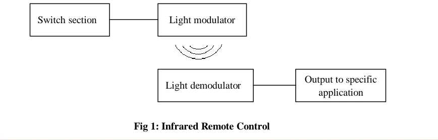
AVAILABLE REMOTE CONTROL SYSTEM: In t he available remote control syst em
there are many t ypes o f disadvantages as per they are mak ing use o f IF co mmunicat ion to
control the ho me appliance just to make it on and o ff, the proble m is that it is strict ly said
to use the remote in t he room it self where we want to control the device. Interference
between the IR transmitter and the IR receiver will create the problem o f loss o f signa l
which ma y create problem o f false swit ching.
[image:2.612.106.540.564.703.2]
Fig 1: Infrared Remote Control
Switch section Light modulator
Light demodulator Output to specific
MODIFICATION IN PRESENT SYSTEM: The new designed system is more flexible and easily controlled by any user the system do have more advance part than IR remote
control as per this modified remote control is making use o f Radio Frequency to control
the appliances. Due to RF signal the syst em will avo id the problem o f false interference
between the remote and the device so as toavo id false interference. The main advantage of
using this system is t hat we can control any appliance in any room fro m any other room
fro m diameter of 100m.
[image:3.612.94.543.583.703.2]
Fig 2: RF Remote Control
II. DESIGNED NEW REMOTE CONTROL SYSTEM
It is completely related with controlling of appliances using remote by which we can control the
appliance from a respective distance of 100m.
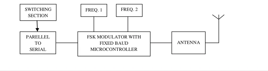
A. REMOTE SECTION: It consists of different blocks to represent the total section of the transmitter
or the remote control.
Switch section RF modulator
RF demodulator Output to specific
application
SWITCHING SECTION
ANTENNA PARELLEL
TO SERIAL
FSK MODULATOR WITH FIXED BAUD MICROCONTROLLER
FIG 3: Remote Section
SWITCHING SECTION: The initial section where the switch is connected to switch ON the
proper appliance to make it on and off. Micro switches are used to make the device on or off.
Switching section is connected with the parallel to serial converter section to convert the pressed
switch into proper data and to convert the parallel data into serial data so as to transmit it using
digital transmission technique FSK.
PARALLEL TO SERIAL CONVERTER: Output from the switching section is given to the
parallel to serial converter where pressed switch is recognized and a proper data is made with
respect to the pressed switch this data from the switch is taken in parallel from and converts form
and the parallel data into serial form to transmit the data.
FSK MODULATOR: Data from the parallel to serial section given to the FSK section to
modulate the signal with respective frequencies. Two different frequencies are used for keying
with respect to the data.
F1: This is the section where the first frequency is generated.
F2: This is the section where the second frequency is generated.
These two frequencies are connected with the FSK modulator section to take respective actions
with respect to data coming serially.
ANTENNA: The modulated signal is taken and is transmitted by converting electrical signal into
electromagnetic waves.
B. RECEIVER SECTION: Signal transmitted from the FSK transmitter is received and decoded
properly to receive the original transmitted signal. Receiver section for all the application is same but
the application changes internally by proper software manipulation.
ANTENNA
FIG 4: Receiver Section
ANTENNA: This section receives the signal from transmitter. It converts electromagnetic waves
into electrical signal which is in the form of frequency and is given to the next section to convert
it into its respective format.
DEMODULATOR: Demodulates the transmitted signal from FSK modulator and generates the
respective data coded from the transmitter. The data is presented in the same 4 bit form as
transmitted from transmitter.
SERIAL TO PARALLEL CONVERTER: Signal from the demodulator section is filtered and
is given to the parallel to serial converter section where the serial data is converted into parallel
for to generate the original signal or the status of the switch which was pressed from the
transmitter.
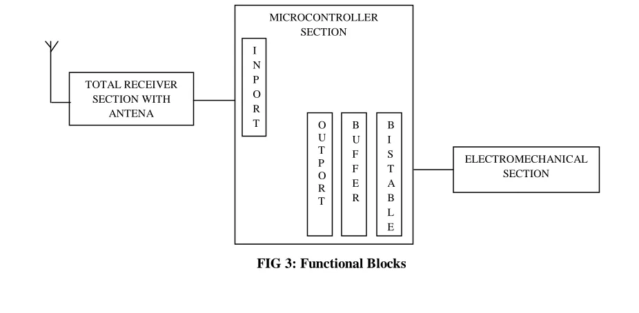
PORT: The port is totally related with the microcontroller where port P1 is used as the input
port where the data from the receiver’s serial to parallel section is given to the port in 4 bit form.
III. APPLIANCE CONTROLLING USING REMOTE
Appliances are controlled by making ON and OFF as per user need, just by controlling the device using
remote.
RECEIVER SECTION: This section receives the data transmitted from the FSK transmitter or
generates the respective data from the switch pressed by the user. The data in the 4 bit form that is given
as input data to the input port of the microcontroller and the microcontroller will behave depending on
the program.
MICROCONTROLLER SECTION: This section manipulates the complete operation by making the device ON and OFF or to control the device or to multiplex the application. The total function depends
on the programming stored in the microcontroller and depending on the program, it manipulates the total
function. This microcontroller has 4 ports which can be used as input as well as output port which
depends on the application used in the project. This same microcontroller is used to manipulate all the 3
applications, which is manipulated one by one.
Appliance controlling using remote
Home light management system
Fan speed management system
BUFFER SECTION: This is a latch section, which is helping the microcontroller to multiplex the
application one of the port of the microcontroller, controls the buffer to allot the proper application. The
buffer is executing 4 bit data operation.
BISTABLE SECTION: It holds the single bit data, but the data set or reset state depends on the clock
for the first clock it sets and for the second clock it resets and vice versa the clock of bistable section is
connected with the buffer, for 4 bit 4 bistable section is made. The output of the bistable section is given
[image:6.612.66.529.464.691.2]to a transistor to drive a relay to control the heavy appliances.
FIG 3: Functional Blocks
MICROCONTROLLER SECTION I N P O R
OPERATION: Here as per the block diagram, the receiver section receives the signal from the transmitter and decodes it by converting it into proper digital data then the data is convert into parallel
form as per the original data transmitted from the FSK transmitter or the switch pressed. The data input
port is port 1 and the data output port is port 2 where the data is given out to control the devices.
A buffer IC is connected to control the multiplexed function of the controller to attend no of
applications. Port 3 is used to control the buffer to handle the other applications from the remote, if the
switch is pressed and released a pulse is transmitted and is received by the receiver section where the
same data is presented as the input port of the microcontroller. This same pulse presented at the output
and is given to bistable multivibrater to fix the on or off function of the device. A relay used to make the
device on or off as per the use of the user.
CONCLUSION
This remote control system is a complete solution for all of the remote control operated application that
may be in home, industry, defense or any other because this system is designed full proof to sustain in
REFERENCES
[1] Dhiren Tejani, Ali Mohammed A. H. Al-Kuwari, Energy Conservation in Smart Home, 5th IEEE International Conference on Digital Ecosystems and Technologies, Daejeon, Korea, May 2011. [2] Chetana Sarode, Prof.Mr.H.S.Thakar ,” Intelligent Home Monitoring System”, International Journal
of Engineering Research and Applications (IJERA) ISSN: 2248-9622 www.ijera.com Vol. 3, Issue 1, January -February 2013, pp.1446 1450
[3] Adamu Murtala Zungeru 1*, Ufaruna Victoria Edu 2, Ambafi James Garba,”Design and
Implementation of a Short Message ServiceBased Remote Controller” Computer Engineering and Intelligent Systems ISSN 2222-1719 (Paper) ISSN 2222-2863 (Online) Vol 3, No.4, 2012
[4] G.RAGHAVENDRAN,” SMS BASED WIRELSS HOME APPLIANCE CONTROL SYSTEM,
2011 International Conference on Life Science and Technology IPCBEE vol.3 (2011) © (2011) IACSIT Press, Singapore
[5] Chetana Sarode, Prof.Mr.H.S.Thakar ,” Intelligent Home monitoring system” , International Journal of Engineering Research and Applications (IJERA) ISSN: 2248-9622 www.ijera.com Vol. 3, Issue 1, January -February 2013, pp.1446-1450
[6] Basil Hamed,” Design and Implementation of smart house control using LabVIEW”, International Journal of Soft Computing and Engineering (IJSCE) ISSN: 2231-2307, Volume-1, Issue-6, January 2012
[7] LabVIEW User Manual, April 2003 Edition, National Instruments
[8] Bitter, Rick, Taqi Mohiuddin, and Matt Nawrocki “LabVIEW Advanced Programming Techniques
“Boca Raton: CRC Press LLC, 2001
[9] National Instruments Corporation, Wireless Sensor Node Data Sheet (NI WSN 3202 & NI WSN 3212), National Instruments Corporation, 2009,
http://www.ni.com/pdf/products/us/cat_wsn32xx.pdf