HIGH BANDWIDTH MICROSTRIP ANTENNA OF ELLIPTICAL PATCH
WITH SQUARE SLOT AND A PIN SHOT
Mahendra Singh Meena
Assistant Professor, Department of Electronics and Communication Engineering, Amity School of Engineering and Technology, Amity University, Haryana.
ABSTRACT
FR4 is an inexpensive and easily available substrate material, which can be used to design
efficient and cost effective microstrip patch antenna. This paper focuses on increasing the
bandwidth of the microstrip patch antenna. Paper discusses about design of a elliptical patch
antenna, having coaxial probe as a feed. To get the improved bandwidth, a rectangular slot has
been digged along with a pin short, which changes the interaction of radiation. A huge increase
in bandwidth is observed using the proposed design; almost 9 fold. All the simulation work is
done using IE3D simulating software from Zeland has been used.
Key words: FR4, elliptical, slot, pin short
Introduction
A Microstrip or Patch Antenna is a low profile Antenna that has a number of advantages over other antennas. It is lightweight, inexpensive, and easy to integrate with accompanying electronics. While the antenna can be 3D in structure (wrapped around an object, for example), the elements are usually flat, hence their other name, Planar Antennas. A Planar Antenna is not always a patch antenna. But use of conventional elliptical microstrip patch antenna alone is very difficult because of its low gain and narrow bandwidth. So to overcome these problems various methods have been tried, some of them are listed in next section. This paper proposes a method in which slots are digged in patch antenna using pin short. Configuration of paper is as follows:
GE-International Journal of Engineering Research
Vol. 5, Issue 5, May 2017 Impact Factor- 5.613 ISSN(O): 2321-1717, ISSN(P): 2394-420X
© Associated Asia Research Foundation (AARF) Publication
Next section is literature review, which is followed by proposed design and in the last some conclusions are drown based on simulation done.
Literature Review
The Gordon et.al described that the band width of microstrip antennas can be increased by using thick substrate but with thick substrate coaxial probe feed introduces inductive component due to which unavoidable impedance mismatch occurs. So the solution to impedance mismatch was found in the form of capacitive feeding mechanism which can be used for annular ring MPA elements, consisted a small capacitor patch in the same layer as in the radiating element. [1]
Gordon et.al experimented on following three designs:
• Rectangular radiating elements,
• Circular radiating elements and
• Annular ring radiating elements
Feeding mechanism was common in all three designs. The position of the probe feed was decided to be in the center of the small patch. Design tool used was IE3D 12th version Zeland, substrate was FR4 with thickness 1.6 mm having dielectric constant 4.4. Height of patch from ground was taken as 15 mm, ground plane was taken as square of 150x150 mm and probe diameter 0.9 mm.
Experimental Results are shown below:
Resonant frequency- 1800MHz
10 dB return loss Band Width-
Rectangular Circular Annular Ring Simulated 25.9% 26.8% 25.9% Measured 26.4% 27.9% 26.1% Gain-
Figure 1 Structure of proposed antenna design for (a) rectangular,(b) circular and (c) annular ring radiating elements (d) side view of anteena.
Dheeraj et. al. proposed modified circular patch antenna to achieve 50.36% efficiency together with 4.10 dBi gain and 8.38% band width. Firstly they taken a circular patch and then an elliptical slot has been cut in it, after this, parallel to major axis of the inserted elliptical slot, splitting is applied and at last this elliptical hole is filled with an elliptical patch between two split halves of circular patch.
FR4 of thickness 1.59 mm and dielectric constant 4.4 was taken as substrate which had loss tangent of 0.0148. Main circular patch radius was taken 12 mm. For inside elliptical patch semi major axis is of 9 mm, semi minor axis is of 4.8 mm and eccentricity is 0.846. Splitting width of circular patch in two halves is 0.25 mm. Ellipse filling the elliptical slot has a = 8 mm and b = 3 mm.
[image:3.612.230.383.501.647.2]Experimental Results are shown below:
Geometries
Resonance frequency,
GHz
Radiation efficiency,
%
Directivity
, dBi Gain, dBi
Bandwidth , %
Circular elliptical ring 4.96 22.48 6.30 1.11 6.02 Gap coupled split
circular patch antenna with circular slot
5.16 53.35 7.61 4.87 6.64
Gap coupled split circular patch antenna with elliptical slot and filled with elliptical
patch
5.01 50.36 7.08 4.10 8.38
Figure 3: Design of proposed antenna
As a result resonating frequencies of 6.23GHz and 6.859GHz (simulating) and 6.66GHz and 7.42GHz (measured) were observed and bandwidth of 15.99% (simulated) and 13.58% (measured) along with Gain of 5.84 at 6.66GHz and 5.71 at 7.42GHz were observed, which is huge improvement over non-slotted design. [3]
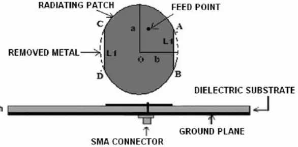
To obtain improved bandwidth and circularly polarized radiation over conventional elliptical antenna, in this paper the elliptical shape patch antenna with truncated edges has been introduced. In [4] tow antennas were studied (1) a conventional elliptical antenna and (2) edges truncated elliptical antenna. FR4 with having thickness of 1.59 mm, dielectric constant of 4.4 and loss tangent of 0.025 was used as substrate. Ellipse patch with semi major axis a = 15 mm and semi minor axis b = 14.43 mm after truncation L1= L2=7.75 mm as shown in figure.
Figure 4 Edge truncated elliptical patch antenna
[image:5.612.169.462.462.607.2]2.692 GHz and (48.49+ j5.34) ohm corresponding 2.802 GHz resonant frequency, Minimum Axial ratio = 0.68 dB at 2.751 GHz, Gain = 1.71 dB at 2.751 GHz
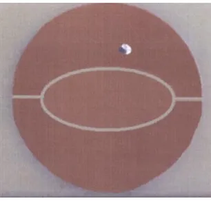
Proposed Design and Results Design Specifications:
In this design elliptical shape microstrip patch has been designed for broadband purposes by cutting a square shape slot and using a pin short. Design specifications of the patch are-
• Resonant Frequency f0 = 7.25GHz • Dielectric Constant ϵr = 4.4
• Substrate Thickness h = 1.59mm
• FR4 substrate is used
Dimension of the patch: Wireless communication requires compact size antenna, which can be easily used in small hand held devices. We have proposed a compact size elliptical shape patch, which can be utilized for the purpose. Dimensions of the proposed antenna are:
• Semi major axis a = 15mm
• Semi minor axis b = 10mm
• Position of the square slot= (0, 5)
• Square slot area = 3mm×3mm
Use of pin short
To obtain the desired bandwidth a pin short at point (2, -2) has been used. The position of pin is in the fourth quadrant while the feed is used in third quadrant at same distance from origin. The pin changes the distribution of current so improves the bandwidth.
Return loss and bandwidth
The return loss with feed only was obtained -19.55dBi which have been improved to -38.84dBi and previously the bandwidth was 2.93% and after modification in geometry improved bandwidth is 21.048%.
Figure 6 (a) and (b) simulated return loss verses frequency graph for conventional elliptical
patch and proposed geometry
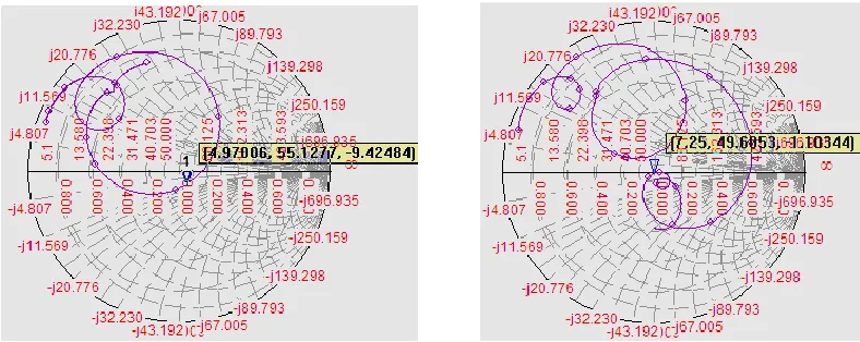
Smith chart
The corresponding smith chart of before modification and after modification in elliptical shape patch is shown in figure below. The figure shows that input impedance of is (55.12- j9.42) for simple feed geometry and (49.68- j1.10) for modified geometry.
Figure 7 (a) and (b) smith chart of conventional elliptical patch and geometry
Radiation Pattern
[image:7.612.100.514.139.313.2] [image:7.612.108.502.464.621.2]
Figure 3.12 (a) and (b) 2D-Radiation pattern of elliptical patch without cut and with cut
Table 1 shows the comparison of results between modified and unmodified geometry
S.
No. Characteristic
Elliptical patch with only feed
Elliptical patch with a slot of
square shape
Elliptical patch with square slot and a pin shot
1. Resonant
frequency(GHz) 4.97 4.99 7.25 2. Return loss(dB) -19.55 -19.47 -38.84 3. Gain (dBi) 1.56 1.63 0.25 4. Bandwidth 2.93 2.968 21.04
5. Antenna
Efficiency (%) 21.52 22.27 16.43
6. Radiation
Efficiency (%) 22.53 23.03 16.82
Conclusions
[image:8.612.105.507.310.569.2]used. For the same dimensions conventional patch had bandwidth 2.93% and proposed design had bandwidth of 21.04%. The proposed antenna can be used a broadband antenna.
References
1. Gordon Mayhew-Ridgers, Johann W. Odendaal, and Johan Joubert, “Single-Layer Capacitive Feed for Wideband Probe-Fed Microstrip Antenna Elements” IEEE Transactions on Antennas and Propagation, Vol. 51, No. 6, June 2003
2. Dheeraj Bhardwaj, Komal Sharma, D. Bhatnagar, S Sancheti & B Soni, ”Design and analysis of a gap coupled split circular patch with elliptical slot filled with elliptical patch” Indian Journal of Radio & Space Physics, Vol. 39, April 2010
3. Garima, D Bhatnagar, J S Saini, V K Saxena& L M Joshi, “Design of broadband circular patch microstrip antenna with diamond shape slot” Indian Journal of Radio & Space Physics, Vol. 40, October 2011.
4. Pratibha Sekra, Sumita Shekhawat, Manoj Dubey, D Bhatnagar, V K Saxena & J S Saini, “Design of circularly polarized edge truncated elliptical patch antenna with improved performance”, Indian Journal of Radio & Space Physics, Vol. 40, August 2011. 5. Puneet Kumar, Mahendra Singh Meena, Ved Prakash , “Bandwidth Enhancement of a
Patch Antenna by using Metamaterials for WLAN Application”, Vol 01, Issue 04, June 2013, 105-109 (ISSN [ 2320-706X ])
6. K. D. Prasad, “Antenna & Wave Propagation”, Satya Prakashan, New Delhi, 2005 7. C. Balanis “Antenna Theory Analysis and Design”, second edition, John Wiley, 1997. 8. Mahendra Singh Meena and Nisha Achra, “A text book of Antenna and Wave
Propagation, College Book Center, 2013, Second Edition
9. R. Garg, P. Bhartia, I. Bahk, A. Ittipiboor, “Microstrip Antenna Design Handbook” Artech House, 2001.
10.R. A. Sainati, “CAD of Microstrip Antennas for Wireless Antennas for Wireless Applications”, Artech House, 1996.
11.D.M.Pozar, “Microstrip Antennas”, Proc. IEEE , Vol 80, pp 79-91
12.Kin-Lu-Wong, “Compact and Broadband Microstrip Antenna”, John Wiley & Sons 2002. 13.Nasimuddin, Zhi Ning Chen, and Xianming Qing, “A Compact Circularly Polarized
14.Mahmoud N. Mahmoud and Reyhan Baktur, “A Dual Band Microstrip-Fed Slot Antenna”, IEEE Transactions on Antennas and Propagation, Vol. 59, No. 5, May 2011 15.Nasimuddin, Xianming Qing, and Zhi Ning Chen, “Compact Asymmetric-Slit Microstrip
Antennas for Circular Polarization”, IEEE Transactions on Antennas and Propagation, Vol. 59, No. 1, January 2011
16.Kunpeng Wei, Zhijun Zhang, and Zhenghe Feng, “Design of a Coplanar Integrated Microstrip Antenna for GPS/ITS Applications”, IEEE Antennas and Wireless Propagation Letters, Vol. 10, 20
17.S N Mulgi, G M Pushpanjali, R B Konda, S K Satnoor & P V Hunagund, “Broadband aperture coupled equilateral triangular microstrip array antenna”, Indian Journal of Radio & Space Physics, Vol. 38, June 2009.
18.G. Mayhew-Ridgers, J. W. Odendaal, and J. Joubert, “New feeding mechanism for annular-ring microstrip antenna,” Electron. Lett., vol. 36, no. 7, pp. 605–606, Mar. 2000. 19.Yoon,W.S., Baik, J.-W., Lee, H.-S., Pyo, S., Han, S.-M., and Kim, Y.-S., “A