I
~ FE411-810C
£
Ji:.
1981-02-20anu I
mulation
Preface
"Reference Manual - IBM 3270 Emulation" presents the Alfaskop System 41 as used in IBM 3270 terminal system applications. Its purpose is to provide you with reference material on the Alfaskop System 41 and the interrelationships among system components.
Chapters 1 and 2 present basic information about system components and terminal system configurations.
Chapter 3 describes the operational characteristics. The commands and orders are defined in chapter 4.
Chapter 5 defines the communication protocol for binary synchronous communica-tion (BSC), remote conneccommunica-tion (IBM 3274 model 1 C).
Chapter 6 defines the SDLC communication protocol and the SNA commands used with this protocol when the IBM 3274 Control Unit (model 1 C, SNA/SDLC version) is emulated.
Chapter 7 defines the communication protocol for local connection (IBM 3274 model 1 Band 1 D).
The specifications in this publication are subject to change or supplementation without notice.
To find out more about the Alfaskop System 41, please contact your Datasaab representative.
This is a revised edition ofpuhlication FE411-810B.
Datasaah AB Alfaskop Division
Documentation Department S -175 86 J ii Ifii /I a, S HI e de n
)
)
(
(
[DnllSMB)
Reader comments
You can help improve future editions of this document by answering the following questions and sending us your comments.
1. Document name and number:
-2.
Myjob:---3. I have used this document
o
To acquire general information (for---)
o
As a technical manual (reference book)o
As a textbook in a course (trainee)o
As source material for teaching a course (instructor)Comments:
-4. I think this document is
o
Easy to find things ino
Easy to find things in with some reservationso
Difficult to find things inComments:
-5. I think this document is
o
Easy to understando
Easy to understand with some reservationso
Difficult to understandComments:
-6. I think this document is
o
Well illustratedo
Poorly illustrated-[~)
7. I think that this document provides
o
Full coverage of the subject at hando
Poor coverage (essential parts are lacking)
Comments:---8. I think that this document is
o
Well adapted to my skills and knowledgeo
Poorly adapted to my skills and knowledgeComments:
-9. Other comments:
-We appreciate your cooperation.
Please send your answers and comments to
Datasaab AB Alfaskop Division
Documentation Department S-175 86 Jarfcilla, Sweden
)
)
(
(
(
[~) System Components
Contents
Introduction _ _ _ _ _ _ _ _ _ _ _ _ _ _ _ _ _ _ _ _ _ _ _ _ _ _
Hardware _ _ _ _ _ _ _ _ _ _ _ _ _ _ _ _ _ _ _ _ _ _ _ _ _ _ _ _ _ _ 2 Communication Processor 4101 _ _ _ _ _ _ _ _ _ _ _ _ _ _ _ _ 2 Communication Processor 4102 _ _ _ _ _ _ _ _ _ _ _ _ _ _ _ _ _ 4 Display Unit 4110 _ _ _ _ _ _ _ _ _ _ _ _ _ _ _ _ _ _ _ _ _ 6
Display Unit Characteristics __________________ 7
Display Unit Operation _ _ _ _ _ _ _ _ _ _ _ _ _ _ _ _ _ _ 7
Keyboard Unit 4140 with Keyboard Expansion Unit 4141 _ _ _ _ _ _ 9
Magnetic Identification Device 4131 10
Selector Pen Device 4130 11
Printer Unit 4154 11
Printer Unit 4154 Characteristics 12
Printer Unit 4153 12
Printer Unit 4153 Characteristics 13
Flexible Disk Unit 4120 13
Flexible Disk Unit Characteristics 14
Flexible Disk Unit Operation 14
Software ________________________________________ ___ 15
15 16 16 16 17 17
Operating System _ _ _ _ _ _ _ _ _ _ _ _ _ _ _ _ _ _ _ _
System Software _ _ _ _ _ _ _ _ _ _ _ _ _ _ _ _ _ _ _ _ _ _ _ Terminal-Console-Functions Software _ _ _ _ _ _ _ _ _ _ Emulation Software _ _ _ _ _ _ _ _ _ _ _ _ _ _ _ _ _ _
Alfaform Package _ _ _ _ _ _ _ _ _ _ _ _ _ _ _ _ _ _
Application Software _ _ _ _ _ _ _ _ _ _ _ _ _ _ _ _ _ _ _ _ _
Illustrations
1. Alfaskop System 41 hardware _ _ _ _ _ _ _ _ _ _ _ _ _ _ _ _ _ _ 2. 3. 4. 5. 6. 7. 8. 9. 10.
II.
12. 13. 14. ~ l:'IJ.
16.
Communication Processor 4101 ___________________ _
Block diagram of Communication Processor 4101 _ _ _ _ _ _ _ _ _ _ _ Communication Processor 4102 ______________________ _ Block diagram of Communication Processor 4102 _________________ _ Display Unit 4110 _ _ _ _ _ _ _ _ _ _ _ _ _ _ _ _ _ _ _ _ _ _ _ _ Examples of character layouts _________________________ _
2 3 4 5 6 7
Block diagram of Display Unit 4110 in cluster configuration 8
Block diagram of Display Unit 4110 in single display-unit configuration _ _ 9
Keyboard Unit 4140 with Keyboard Expansion Unit 4141 9
Magnetic Identification Device 4131 _ _ _ _ _ _ _ _ _ _ _ _ _ _ _ 10 PrinterUnti4154 _ _ _ _ _ _ _ _ _ _ _ _ _ _ _ _ _ _ _ _ _ _ 11
Printer Unit 4153 14
Flexible Disk Unit 4120 13
Biock diagram of Flexible Disk Unit 4120 15
System software 16
(
(
)[Dm'a9MB) 1
System Components
Introduction
The Alfaskop System 41 was made possible by a long-term development program that embraced ergonomics, state-of-the-art terminal system architecture and sophisticated software systems.
The Alfaskop System 41 used in IBM 3270 emulations is an intelligent, programmable terminal system that prepares and sends information to an IBM host computer and obtains information in return.
The Alfaskop System 41 hardware consists of communication processors, display units, printer units and flexible disk units which can be combined in various configurations.
2 System Components [~l
A system component is a functional hardware or software unit. The system components mentioned in this section can be used in a terminal system intended for IBM 3270 emulations.
Alfaskop System 41 features are categorized as specify features or extra features. A specify feature must be included in a functional system. An extra feature is an optional feature that improves performance, provides additional operational capability, or permits expansion of the system.
Hardware
Communication Processor 4101
Communication Processor 4101 is intended for modem connection via the CCITT V 24/28 interface. Transfer rates range up to 9600 bps.
The communication processor controls communication between the host computer and the terminals. The communication processor is used in configurations where more than one display unit or more than one printer are to be connected to the same modem (cluster configurations).
The basic version of Communication Processor 4101 can accommodate up to eight terminal connections and can be connected to one host computer.
Communication Processor 4101 can be expanded to provide
- Up to 32 terminal connections
- Two host computer connections via modem/communication lines (Soft-ware on an RPQ basis)
Fig. 2. Communication Processor 4101
)
[~)
(
(
(
(
System Components 3
Functionally, Communication Processor 4101 can be subdivided as fol-lows
• Synchronous Communication Adapter 4194
.. Microprocessor
• Memory
• Memory expansion
• Direct memory access
• Terminal selection control
• Terminal unit adapter
To modem
To modem
1) Specify feature 2) Extra feature
Synchronous Communication Adapter4194 1)
Synchronous Communication Controller41951) 2)
Microprocesspr
Memory
Memory expansion
Communication Processor 4101
Fig. 3. Block diagram o/Communication Processor 4101
The synchronous communication adapter converts serial data, received from the communication line,. to parallel data used in the communication processor and vice versa. Line transmission is synchronous and can com-ply with either the BSC or the SDLC protocol.
The microprocessor is an 8-bit LSI processor with an addressing capability of 64 kilobytes.
4 System Components [~)
One terminal unit adapter is included in the basic version of the communi-cation processor. It enables eight two-wire cables (or coaxial cables) to be connected to the communication processor. Each additional Terminal Unit Adapter 4181 expands the number of two-wire (or coaxial) connec-tions by eight. The maximum number of the connecconnec-tions is 32.
The terminal unit adapter consists mainly of a switch matrix that is con-trolled by the microprocessor via the terminal selection control.
Direct memory access (DMA) transfers are initiated by the microproces-sor. DMA transfer includes
• Internal polling of terminals
• Host computer communication
• Internal communication between terminals
If a display unit requests a data transfer to an assigned flexible disk unit, the microprocessor makes the connection by sending control information to the terminal selection control. The display unit then addresses the flexible disk unit directly and the microprocessor is asked to break the connection when the transfer is completed.
Communication Processor 4102
Communication Processor 4102 is intended for local connection to an IBM selector, block multiplexer or multiplexer channel.
The maximum instantaneous data transfer rate is 650,000 bytes per second for write operations and 400,000 bytes per second for read operations.
The basic version of Communication Processor 4102 can accommodate up to eight terminals. Communication Processor 4102 can be expanded to provide up to 32 terminal connections.
Fig. 4. Communication Processor 4102
)
[~I
(
(
System Components 5
Functionally, Communication Processor 4102 can be subdivided as fol-lows
• Channel communication controller • Microprocessor
• Memory
• Memory expansion • Direct memory access • Terminal selection control • Terminal unit adapter
Communication Processor 4102 is built up on the same principles as Communication Processor 4101. It differs only with regard to the com-munication interface.
The channel communication controller is designed for direct connection to an IBM System 360/370 or IBM 3030/4300 Series data channel.
The rest of the functional blocks are the same in the two communication processors.
Channel
I@
To channel communication
:@
controller
Microprocessor
I@
l@
Memory
i~
I 8
10
Memory
expansion
10
Communication Processor 4102 1) Specify feature
2) Extra feature
6 System Components
Display Unit 4110
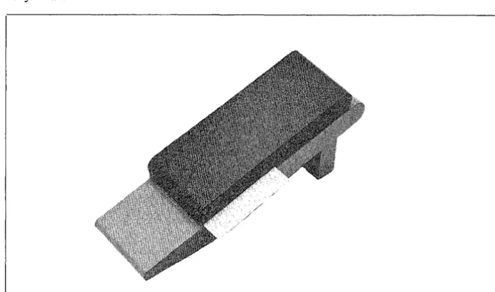
Display Unit 4110 is an attractive, operator-oriented cathode ray tube display.
The display unit features an anti-glare screen, and it is also equipped with a pull-out hood which eliminates reflections encountered in poor lighting. The display unit can be tilted and swiveled, thus ensuring comfortable, convenient viewing for each individual operator.
Fig. 6. Display Unit 41/0
The screen has a capacity of 480-3440 characters. Program-defined screen formats include
Lines x characters: 12 x 40
12 x 80 24 x 80 32 x 80 43 x 80
Each format is provided with an extra line for terminal system messages.
Each character is displayed in a character cell consisting of 9 x 16 dots (except in 32- and 43-line formats), thus ensuring crisp, clear characters and minimizing risk of misreading.
Fields can be displayed with high or normal brightness, and they can also be made nonvisible. Flashing text and underlining are also provided. The cursor can be displayed either as an underscore or a filled rectangle. The cursor can flash or glow steadily.
Display units are available for cluster configurations (connection to the communication processor) and single display-unit configurations (modem connections).
)
(
{
\
(
[DA"mSUB) System Components 7
Display Unit Characteristics
Effective screen size:
Character cells:
Dot matrices:
Refresh rate:
Screen colour:
•
..
.:
e a .
~
-
••
• •
-
•
•
•
-
•
• •
•
•
•
•
•
•
•
Fig. 7.
Display Unit Operation
Height 180 mm Width 258 mm
9 horizontal x 16 vertical dots 9 x 12 for 32-line formats 9 x 9 for 43-line formats
7 x 13, 7 x 9 and 7 x 8
50Hz
Amber
•
•
•
•
•
•
•
•
•
•
•
•
•
•
•
•
~•
~.
•
•
--Examples of character layouts
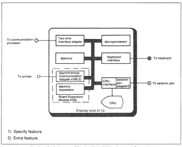
Functionally, Display Unit 4110 can be subdivided as follows
• Microprocessor
• Memory
• Memory expansion
• Two-wire interface adapter
• Keyboard interface
• Cathode ray tube unit (CRU)
• CRU interface
• Selector pen adapter
• Synchronous Conlnlunication Adapter 4194 (single display-unit config-uration)
[image:13.595.100.494.102.652.2]8 System Components
To communication processor
Two-wire • • •
} - - i l - - ! interface adapter filii
Memory
To printer
Display Unit 4110
1) Specify feature 2) Extra feature
I---!IIII---<oo To keyboard
I-IIIJ~----(. To selector pen
Fig. 8. Block diagram of Display Unit 41/0 in cluster configuration
The microprocessor is an 8-bit LSI processor with an addressing capability of 64 kilobytes.
The basic memory has a capacity of 32 kilobytes and it can be expanded to a maximum of 64 kilobytes. Board Expansion Module 4183 is needed if the memory is to be expanded.
The display unit is connected to the communication processor via a two-wire cable. Coaxial cable can also be used. The two-two-wire interface adapter includes circuits that provide galvanic isolation from the communication processor.
The two-wire interface adapter converts serial information, sent to/from the communication processor, to parallel data used in the display unit. The data sent on the two-wire cable is frequency-modulated and the transfer rate is 300 kilobits per second. The interface adapter also includes circuits for direct memory access.
\ )
[image:14.595.150.509.75.365.2](
(
[~l System Components 9
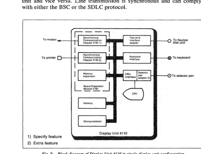
When the display unit is used in single display-unit configurations the interface adapter serves as an adapter for the flexible disk unit.
Synchronous Communication Adapter 4194 is the same adapter that is used in Communication Processor 4101. The adapter converts serial data received from the communication line to parallel data used in the display unit and vice versa. Line transmission is synchronous and can comply with either the BSC or the SDLC protocol.
Ir -
-::;l
Synchronous
To modem ___ ---I--f-l Communication . . . . Adapter41941) pill
To printer
1) Specify feature 2) Extra feature
Asynchronous Communication Adapter 4193 2)
Memory expansion
Memory
Display Unit 4110
To flexible disk unit
[image:15.600.89.492.151.459.2]HIIIIIt--~1)() To keyboard
... ~--(.. To selector pen
Fig. 9. Block diagram of Display Unit 4110 in single display-unit configuration
Keyboard Unit 4140 with Keyboard Expansion Unit 4141
The keyboard consists of a basic module plus an optional expansion unit which can be located either to the right or left of the basic module.
The keyboard is connected to the display unit via a I-metre cable and can thus be positioned as desired relative to the display unit.
The keyboard incorporates a microcomputer which controls and supervises its operations.
10 System Components I~l
Keyboard features include
~ Up to 127 keys
~ Clicking sound (adjustable volume) which acknowledges keyed entries
~ Alarm signal (adjustable volume and pitch) for illegal keyed entries
~ Indicator lamps that are lighted and extinguished by signals from the terminal system and/or host computer
~ Keyboard slope can be adjusted in two steps
~ Palm rest
The following basic types of keyboards are available for Display Unit 4110
~ Typewriter keyboard with basic typewriter key layout. Alphanumeric keys are encoded with both lower case and upper case characters.
~ Data entry keyboard with basic data-entry type of layout. When numeric characters are entered in a numeric field, the keyboard is automatically upshifted to take advantage of the grouped numeric keys. When lower shift characters are to be entered in a numeric field the ALPHA SHIFT key has to be used.
~ APL keyboard allows the entry of characters oriented to APL program-ming applications.
Magnetic Identification Device 4131
The magnetic identification device reads magnetically encoded ID-cards containing up to 37 ID-characters plus three control characters.
The magnetic identification device is a separate unit connected to the keyboard via a 1-metre cable.
Fig. 11. Magnetic Identification Device 4131
)
[image:16.600.148.506.553.764.2](
(
(
(
[~l System Components 11
Selector Pen Device 4130
The Selector Pen Device 4130 consists of a selector pen with a fibre optic cable and a selector pen adapter.
The selector pen is connected to the display unit via the fibre optic cable. The selector pen adapter is inserted into the display unit.
The selector pen is used to select among a number of predefined fields on the screen, whereupon the computer and/or terminal system can carry out certain operations that have been defined for the field in question.
Printer Unit 4154
The free-standing, pedestal-mounted printer unit provides hard copies of information appearing on the display screen or data obtained from the host computer system.
The buffered printer unit is connected to the display unit, and it can be located at a distance of up to 600 metres from the display unit.
12 System Components [~l
Printer Unit 4154 Characteristics
Dot matrix:
Character set:
Printing speed:
Characters per line:
Horizontal spacing:
Vertical spacing:
Paper feed:
Paper format:
Paper copies:
9x7
95 graphic symbols including upper/lower case letters, numerals, special
characters and space.
100-125 lines per minute
132
10 characters per inch
6 or 8 lines per inch
Tractor
Min width, 4 inch (l05 mm) Max width, 16 inch (406 mm)
Top copy plus 4 on 45 g/m2 printing paper. Max thickness of paper plus carbon, 0.4 mm
Printer Unit 4154 incorporates the form feed function as standard. The vertical tabulation function is an extra feature.
Printer Unit 4153
Printer Unit 4153 is a free-standing desk-top unit. This buffered printer is connected to the display unit, and it can be located at a distance of up to 600 metres from the display unit.
FiR. 13. Printer Unit 4153
)
(
(
(
[~) System Components 13
Printer Unit 4153 Characteristics
Character structure: Printing speed: Characters per line: Character set: Horizontal spacing: Vertical spacing: Paper feed: Paper format: Paper copies:
9 x 9 dot matrix
Up to 250 characters per second 90-130 lines per minute
Max 154
95 graphic symbols including upper/lower case letters,
numerals, special characters and space 10 characters per inch
6 lines per inch Tractor
Min width, 2" (50 mm) Max width, 17.8" (450 mm)
Top copy plus 5 on 50 g/m2 printing
paper. Max thickness of paper plus carbon, 0.55 mm.
Printer Unit 4153 incorporates the form feed and vertical tabulation func-tions as standard.
Flexible Disk Unit 4120
The flexible disk unit, which provides secondary storage for the display system, can be connected to the communication processor.
The flexible' disk unit can also be connected to a single display-unit configuration.
14 System Components
Flexible Disk Unit Characteristics
N umber of diskettes:
Capacity:
Access time:
Transfer rate:
Rotational speed:
Recording density:
Track density:
Tracks:
Media requirements:
Flexible Disk Unit Operation
Max 2
256 kilobytes per diskette with IBM 3740 sectoring (128, 256, 512 or 1024 bytes per sector)
Track-to-track, 8 ms
A verage (including settling), 93 ms Settling time, 10 ms
Head load time, 40 ms
250 kilo bits per sec
360 rfmin
3408 bpi
48 tpi
77 (one side)
IBM diskette or equivalent
The flexible disk unit contains a microcomputer which controls and supervises diskette storage and readout operations.
The flexible disk unit also incorporates a file handling system, thus limiting tasks carried out by the communication processor or display unit to opening and defining files, after which data can be read or stored. Moreover, data can be read from one diskette to another within the flexible disk unit.
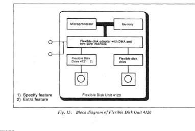
Functionally, Flexible Disk Unit 4120 can be subdivided as follows
• Microprocessor
.. Memory
• Flexible disk adapter with direct memory access transfer
• Flexible disk drive
The microprocessor is an 8-bit LSI processor.
Memory capacity is 32 kilobytes.
The flexible disk adapter provides direct memory access at a rate of 300 kilobits per second. The flexible disk adapter also includes circuits that provide galvanic isolation from the communication processor or display unit.
(
(
(
(
[~l System Components 15
As standard, the f1.exible disk unit is equipped with one flexible disk drive. An extra Flexible Disk Drive 4121 can be inserted into the flexible disk unit.
1) Specify feature 2) Extra feature
Microprocessor • • • Memory
Flexible disk adapter with DMA and two-wire interface
Flexible Disk Unit 4120
Fig. 15. Block diagram of Flexible Disk Unit 4120
Software
The Alfaskop System 41 software is divided into three main parts
• Operating system
• System software
• Application software
Operating System
All software components operate under the control of, and with the as-sistance of, an operating system that permits a number of programs, communication lines and terminals to be handled and processed concur-rently_
The operating system carries out
• CPU scheduling
• Memory management
• Interrupt-initiated program control
• I/O
processing• Start/restart initialization
[image:21.602.120.502.121.379.2]16 System Components [~l
The operating system that is used in the terminal and the communication processor consists of modules used by .both.
System Software
The terminal-console-functions software, the emulation software, and the Alfaform package are called system software.
Terminal-console-functions software
Emulation software 1)
Aifaform package 2)
1) Specify feature 2) Extra feature
Fig. 16. System software
Terminal-Console-Functions Software
The terminal-console-functions software provides numerous functions such as
«& Dump functions «& Test functions
«& Internal and external communication line monitoring
• System utility functions (including flexible disk utilities)
«& System customizing
To ensure privacy and security, there are five degrees of authorization implemented using combinations of customer and Datasaab passwords.
Emulation Software
The following IBM 3270 system emulations are available with the Alfaskop System 41
«& Control Unit 3274 IB and ID with Display Station 3278, models 1,2,3
and 4.
)
)
(
System Components 17
CD Control Unit 3274 1 C, remote operation BSC, with Display Station 3278,
models 1, 2, 3 and 4.
CD Control Unit 3274 lC, remote operation SNA/SDLC, with Display
Sta-tion, models 1, 2, 3 and 4.
Alfaform Package
T~AlfafOrm
package is designed to reduce loads on thecommunicat~//~
line aQd host computer by handling part of the processing withiIythetermin~l\
,
This is achieved by means of the following / //
CD Forms
de~ed
and maintained by terminal user in cooperay6n with thehost comput~ system. A form is a definition of a display'layout which specifies the fiX,fd data and the checks that are to
,9'
carried out on entered (variable),~ata. These checks can be of 9fe following types: numeric/alphanumerl«{ field length, check digityHlax/min value,cross-field, etc. '\"'''- /
''';''''' / /
CD Fixed texts stored locally t"o'".supplemenyinessages received from the
host computer ' " , / / /
CD Numerous editing and checking
~ti,<\ns
carried out on data entered viathe keyboard before it is sent)6' the
ho~computer
/"
• Operator training
carrie~t
off-line "" .,
/
""
The Alfaform
p~aka
/ which executes thesefunct~
has been designed so that they can b· implemented with minimum impa~ on existing appli-cation program in the host computer. Alfaform also "'Nrmits different terminals wit In the same cluster configuration to work c'cmcurrently ondifferent a lications.
'~
'""
.... ''''''~.~,Application Software
T~~pPlication
programs inclJ.loeJorms defined in Alfaform.~','
The
PPlic~y'n p';{jgr~~s'(user-w~ite~ .a:-e/Sf;;;;d'ih",~he
flexible disk unit toget er wIth the operating system and tlie system programs.\
/
..
'"'''',,',.,'''', .. ,'''''\
/
)
(
(
(
[~l Configurations
Contents
Examples of Terminal System Configurations _ _ _ _ _ _ _ _ _ _ _ _ _ _ 3 3 3
Single Display-unit Configurations _ _ _ _ _ _ _ _ _ _ _ _ _ _ Cluster Configurations _ _ _ _ _ _ _ _ _ _ _ _ _ _ _ _ _ _
Illustrations
l. Cluster configuration connected to remote host computers 1 2. Chain of peripherals connected to a communication processor 2 3. Example of single display-unit configuration with remote connection to
host computer 2
4. Single display-unit configuration 4
5. Single display-unit configuration that includes Printer Unit 4153/54 5
6. Remote cluster configuration 6
7. Remote cluster configuration that includes Printer Unit 4153/54 7
8. Local cluster configuration 8
9. Local cluster configuration that includes Printer Unit 4153/54 9
)
(
(
(
(
I~l 1
Configurations
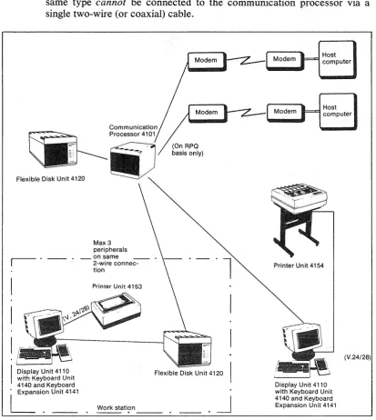
A single display unit can communicate directly with the host computer. A display unit included in a cluster configuration (comprising a number of display units, printer units or flexible disk units) can communicate with the host computer that serves the entire cluster under the supervision of a communication processor.
A cluster configuration can be connected remotely to the computer via modem lines or connected locally to an IBM System 360/370 or IBM 3030/4300 Series selector, block multiplexer or multiplexer channel. A maximum of 32 display units and printer units in any combination can be connected to the same communication processor. One display unit, one printer unit and one flexible disk unit can be connected to the same two-wire cable (or coaxial cable). Two or three peripheral units of the same type cannot be connected to the communication processor via a single two-wire (or coaxial) cable.
Host computer
Host computer
Flexible Disk Unit 4120
r - .
Max 3 peripherals _on same
2-wire connec-tion
Printer Unit 4153
Display Unit 4110 Flexible Disk Unit 4120 with Keyboard Unit
4140 and Keyboard
i
ExpanSi~n
Unit 4141 • Work stati?n _ _ _ , • _ _ •~
Printer Unit 4154
Display Unit 4110 with Keyboard Unit 4140 and Keyboard Expansion Unit 4141
Fig. I. Cluster configuration connected to remote host computers
[image:27.595.86.500.305.767.2]2 Configurations [~l
The maximum overall length of the cable from the communication proces-sor to the display unit is 1500 m for the two-wire cable and 600 m for the coaxial cable. The printer unit is connected to the display unit via a V24/28 interface. The maximum overall length of the printer cable is 600 m.
The display unit and the flexible disk unit are connected in a chain and the display unit must be at the end of the chain. This is because the flexible disk unit has two connectors, one for the cable to the communication processor and one for the cable to the display unit in the chain. The display unit has only one connector.
Fig. 2. Chain of peripherals connected to a communication processor
Communication Processor 4101
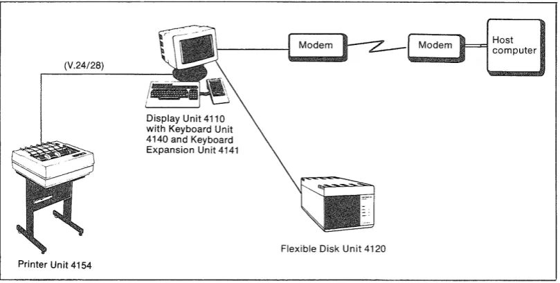
A single display-unit work station can communicate with the host compu-ter via a modem line.
The display unit is connected to the modem. The flexible disk unit is connected to the display unit via a two-wire (or coaxial) cable. The maximum overall length of the two-wire cable is 1500 m and the maximum overall length of the coaxial cable is 600 m. The printer unit is connected to the display unit via a V24/28 interface. The maximum overall length of the printer cable is 600 m.
(V.24/28)
Printer Unit 4154
Display Unit 4110 with Keyboard Unit 4140 and Keyboard Expansion Unit 4141
Flexible Disk Unit 4120
Host computer
Fig. 3. Example of single display-unit configuration with remote connection to host computer
)
)
[image:28.595.103.508.551.755.2](
(
(
(
[~I Configurations 3
Examples of Terminal System Configurations
Single Display-unit Configurations
Figs. 4 and 5 show how the system components used in a single display-unit configuration can be arranged .
Cluster Configurations
Figs. 6 and 7 show how the system components used in a remote cluster configuration can be arranged and Figs. 8 and 9 show how the system components used in a local cluster configuration can be arranged.
The sum of the display units and printer units that can be connected to a
~
~V)
s·
OQ
~
~
~
:s-'<
.::
~
:::;:
(")
c ~
OQ
:;::
's::;
g.
;::
To modem
Alfaskop System 41 Software
Operating system
Terminal-console-function software
Emulation software 1)
1
Alfaform package 2) Application software
Memory
Microprocessor
Display Unit 4110
'-..-.
Microprocessor Memory
....-~
-Flexible disk adapter with DMA and two-wire interface
Flexible Disk Unit 4120
Kevboard Unit 4140
Selector Pen Device 4130
\
\...-\
\,
Keyboard Expansion Unit 4141
Magnetic Identification Device 4131
1) Specify feature 2) Extra feature
..J:>.
~
~
OQ
:;:: s::;
g.
~
'"
?
;.-. V:l s' ()q ;;-~ {j ~ ~ ~ ::::.' t"') C) ~ ()q :::: ~ 6-~ ;;. ~ s' t"') ~ f} '"~
~ ... ~ ::::.' oil.. ... ~ ~..,."..-..., .--.,.
Alfaskop Sysfem 41 Software
Operating system
Terminal-console-function software Emulation software 1)
Alfaform package 2) Application software
To modem 4111 I I I
p,;~~--1) Specify feature 2) Extra feature
r-"-\
Display Unit 4110
Flexible Disk Unit 4120
Keyboard Unit 4140
?
?' ::0 'I>~
'I>:::.. I To modem
s;::
~
~
'"'
c:i
S, I Tomodem
(i(: s;:: ..., §. § Synchronous Communication Adapter 4194 1)
Synchronous Communication Controller 4195 1) 2)
Microprocessor
Memory
Memory expansion
Communication Processor 4101
'-'
Two-wire
interface adapter
Memory
,--,
I
.
I
Memory expansionL
Board Expanslon~ " IModule 4183
----Microprocessor Memory
Flexible disk adapter with DMA and two-wire interface
Flexible Disk Unit 4120
\...-"
Keyboard Unit 4140
Selector Pen Device 4130
Keyboard Expansion Unit 4141
Magnetic Identification Device 4131
Alfaskop System 41 Software
[ Operating system
I -
Terminal-console-function softwareEmulation software 1)
~~-2)
J"
Application software
1) Specify feature 2) Extra featu re
0\ (J
~
(i(: s;:: t:1 g. ;::: '"?
:'-.l ::tl'"
~ ~ '" <"'l ~ ~'"
.... <"'l ~ ~ 00 l::: i:5 6-;: So ~ s· <"'l ~ ~ '"~
~ .... ~ ::;: ~ ... ~ ~To modem
CI!III--To modem
CI!III--Printer Unit 4153/54
Synchronous Communication Adapter4194 1)
Synchronous Communication Controller 4195 1) 2)
Microprocessor
Memory
Memory expansion
'"
Communication Processor 4101
j"""-""',
\
\
, \ \\
"~"UI I I I
Two-wire interface adapter Memory Memory expansion Asynchronous Communication Adapter 4193 2)
Microprocessor
Keyboard interface
~rd ~a~n ~dU~l~
Display Unit 4110
Microprocessor Memory
Flexible disk adapter with DMA and two-wire interface
Flexible Disk Unit 4120
"~ ' \
Keyboard Uni! 4140
Selector Pen Device 4130
Keyboard Expansion Unit 4141
J
I
1
Magnetic Identification Device 4131Alfaskop System 41 Software
[ Operating system
c-rerminal-~onsol~~f-unction software
[Em~lation soft~;;~ 1) --Alfafo'rm package 2)
Application software
1) Specify feature 2) Extra feature
~
?o ~ Cl <"l ~ <"l ~ "'" ~ ... <"l Cl ~ OQ ;: ~ S· ;::: To channel Channel communication controller Microprocessor Memory Memory expansionCommunication Processor 4102
\...
Two-wire interface adapter
Memory
Memory expansion
I
I
7I
L
Board Expansion IModule 4183 ---I
----Display Unit 4110
Microprocessor
Microprocessor
Keyboard
interface
Memory
Flexible disk adapter with DMA and two-wire interface
Flexible Disk Unit 4120
'",-"
Keyboard Unit 4140
Selector Pen Device 4130
Keyboard Expansion Unit 4141
J
I
1
Magnetic Identification Device 4131
Alfaskop System 41 Software
Operating system
Terminal-console-function software
Emulation software 1)
~m package 2) Application software
1) Specify feature 2) Extra feature
~ ~ ~ t""4 (::l ~ 1::.. ~ ~ "" iii ... ~ (::l
.g,
OQ l::: ~ 6' ;:: So ~ s' ~ ~ ~ ""~
iii ...~
-I:a.. ... ~ ~I - I I LI"
Printer Unit 4153/54
Channel communication controlier
[ Mi,mpm,"'"
[:::
[
Memory expansion
"
"-Communication Processor 4102
,....--" .~
"
"-""
"'-"
"-... Two-wire interface adapter Memory Memory expansion Asynchronous Communication Adapter 4193 2)~rd~a~n ~du~"d
Microprocessor
Keyboard interface
Display Unit 4110
Microprocessor Memory
Flexible disk adapter with DMA and two-wire Interface
Flexible Disk Unit 4120
.~ \
Keyboard Unit 4140
Keyboard Expansion Unit 4141
I
1
~l Magnetic Identification Device 4131 Selector Pen Device4130
Alfaskop System 41 Software
- - -
-Operating system
Terminal-console-function software
Emulation software 1)
Alfaform package 2)
Application software
1) Specify feature 2) Extra feature
)
[~l OperationaL Characteristics
Contents
Display Unit Presentation Cursor Automatic SkipControls and Indicators Message Line
Typewriter Keyboard Keys Alphanumeric Keys
(
Edit KeysOperational Keys
Program Attention Keys Data Entry Keyboard Keys
(
10-Key Numeric KeybankNumeric Lock Keyboard Locking Alarm
Magnetic Identification Device Selector Pen Device
Printer Unit
Printer Modes Printer Classes
Printer Authorization Matrix
Controls and Indicators for Printer Unit 4154 Controls and Indicators for Printer Unit 4153 Communication Processor 4101
Controls and Indicators
( Flexible Disk Unit 4120
Controls and Indicators
(
Illustrations1. Example of display formatting _ _ _ _ _ _ _ _ _ _ _ _ _ _ _ _ _ _ 2. Display unit controls and indicators _ _ _ _ _ _ _ _ _ _ _ _ _ _ _ _ 3. Keyboard indicator panel _ _ _ _ _ _ _ _ _ _ _ _ _ _ _ _ _ _ _ _
4. Keyboard controls _ _ _ _ _ _ _ _ _ _ _ _ _ _ _ _ _ _ _ _ _ _
)
(
(
(
(
Operational Characteristics
Display
Unit
Presentation
Data stored in the display area is presented on the screen in the form of alphanumeric characters and symbols. When a keyboard is connected, text can be entered from the keyboard and presented on the screen.
The computer can communicate with the operator in two ways
• The computer or Alfaform formats the display on the screen and the operator is thus provided with a form into which he enters the message.
• The screen display is left unformatted by the computer and the operator himself determines how the message will be arranged on the screen.
The display on the screen is formatted by the use of attribute characters to define the various data fields on the screen. A data field can start at any position on the screen. It is established by an attribute character which defines the display area extending forward to the next attribute character. Each attribute character occupies one position and is presented as a space on the screen.
CD Attribute character. Not displayed.
C%l Protected field. Displayed at normal brightness. Q) Unprotected field. Numeric entries only. High brightness.
@) Unprotected field. Alphanumeric entries. High brightness.
Fig. 1. Example of display formatting
The attribute character contains information indicating
• Whether the field is protected or unprotected from operator entry
• The type of entries which the operator can make into unprotected fields - Numeric entries only
2
Cursor
OperationaL Characteristics
• Which one of the following brightness levels is called for - Off (field not displayed)
- Normal - High
• Whether or not the field is selector-pen-detectable
[~l
• Whether or not the field has been modified by the operator using the MDT bit.
All positions on the screen can be addressed individually, and the com-puter can thus write at any character position. Position addressing can be repeated within a message so that data can be written at different parts of the screen without having to transmit all the text on the screen.
A special symbol, called a cursor, is displayed on the display screen to indicate where the next character entered from the keyboard will be stored.
The cursor is automatically generated by the terminal system and may appear as an underscore, as a flashing underscore, or as a rectangular or flashing rectangular symbol imposed over a character. The character within the rectangular cursor remains visible (inverse video). The operator can change the cursor from an underscore to a rectangular symbol, or vice versa, by pressing the alternate cursor (CD AL) key. The same operator can cause either type of cursor to flash by using the cursor blink (CD BL) key. When the cursor is displayed under one character in a line of characters, the character can be changed or deleted by keyboard action. Also, if the cursor is displayed under (or within) an unprotected position without a display character, a character can be entered in that position by keyboard action. When a character is entered from the keyboard, the cursor moves one position to the right.
The cursor is not affected by keyboard locking but is extinguished for part of the time during which the display unit communicates with the computer.
The cursor is nondestructive and can be advanced, backspaced, or moved up or down without erasing the characters it passes. If a character is entered in the last position of a line, the cursor advances to the first position on the next line, or if the line is the last line of the screen the cursor is moved to the first position on the top line. If the backspace key is used when the cursor is in the first position of the top line, the cursor will appear in the last position of the bottom text line (automatic wraparound). When data is transmitted to or from the computer, the cursor is not affected unless the computer data contains an order calling for cursor movement.
Automatic Skip
When formatted presentation is used and the operator enters a character in the last position of an unprotected field, an automatic cursor movement
)
)
(
(
(
(
Operational Characteristics 3
determined by the succeeding attribute character will be performed in the following manner
• If the attribute character specifies the next field as numeric and pro-tected, the cursor is automatically positioned at the first character posi-tion in the next unprotected field.
• For other attribute characters, the cursor moves to the position follow-ing the attribute character, i.e. the first character position in that field.
Controls and Indicators
The display unit is provided with the following controls and indicators
• Power on/off switch with indicator that lights up when display unit power is switched on
• Brightness control for regulating display brightness
• Contrast control for regulating the difference between text fields having high and normal brightness
• Reset switch. Should not be used by the operator
• Different texts are displayed on message line, e.g. while the program is being loaded into the display unit.
Contrast control
4 Operational Characteristics [~l
An indicator panel located at the top of the keyboard informs the operator of the terminal status. This panel contains the following indicator lamps (in all versions of the keyboard)
• SYSTEM READY Indicates readiness for traffic with the computer
~ USM Indicates that the computer has an unsolicited
message for the operator
~ INSERT MODE Indicates that the INS MODE key has been de-pressed, i.e. that the display unit is operating in the insert mode
• SHIFT Indicates that the keyboard is in the upper shift mode, i.e. shift key is depressed or SHIFT LOCK key has been depressed
• NUMERIC Indicates that the cursor is in a numeric entry field .
• 1/0 ERROR Indicates an error in an external unit (a printer for example)
• KB LOCK Indicates that the keyboard is locked
.ID Used only when the magnetic identification
de-vice is included and in such case it indicates that the ID-card has been read correctly
Fig. 3. Keyboard indicator panel
Three controls are located on the keyboard
~ Audible alarm volume control
~ Audible alarm pitch control
• Click volume control for regulating the volume of the clicking sound that acknowledges keyed entries
(
(
(
(
Operational Characteristics
Alarm volume Alarm pitch
control control
Fig. 4. Keyboard controls
Message Line
Click volume control
5
The bottom line on the screen is used to present detailed information about the status of the terminal system.
Appendix 4 presents the messages that can appear on the message line.
Typewriter Keyboard Keys
Functionally, the keyboard keys can be subdivided as follows
• Alphanumeric keys for
- Letters, numerals and symbols
• Edit keys for - Cursor control - Tabulation - New line - Erasing
- Insertion or deletion of data - Cursor to message line - Cursor'blink
- Alternate cursor
• Operational keys for
- Cancellation of transmission requests and keyboard locking - Reception of unsolicited message
- Rolling the message line - Cancellation of print requests
6 Operational Characteristics
• Program attention keys for - Initiation of data transmission - Selector pen detection function - Clear the display screen
- Test requests - Program access - Program function
• Keyboard expansion unit with - Program function keys
- IO-key numeric pad,
+, -, .
and*
keys - Tabulation, enter and space keys[~l
All alphanumeric, special symbol, and move cursor keys have typamatic capability. If the key is kept depressed more than 0.5 s, the key function is repeated at a frequency of 10Hz.
Alphanumeric Keys
The keys in the large keybank at left are used to enter alphanumeric characters including special symbols. Their functions are tabulated below.
Shift
Shift lock
a
o
Character
Minus-sign/ Underline
Space
The shift keys function in the same way as on an ordinary typewriter, thus enabling the operator to select either upper or lower case characters.
Locks the shift key at its depressed position. This lock is cancelled by depressing the SHIFT key.
One of two modes can be selected inside the terminal. In the dual case mode, lower case characters are dis-played when the shift key is up and upper case characters when the shift key is down. In the mono case mode, all alphabetic keys provide upper case characters regardless of the shift key.
The character is entered at the cursor position after which the cursor is moved forward to the next position.
When the shift key is up this key enters the minus sign
(-).
When the shift key is down this key instantly under-lines a full word by entering a space at the cursor position and underlining the succeeding characters as far as the next space.
The keyboard unit has one space key and the keyboard expansion unit has one space key. Both function identically, causing the cursor to be moved one posi-tion to the right and any character located at the cursor's original position to be erased - thus leaving a blank space.
)
Edit Keys
(
(
(
(
Operational Characteristics 7
The edit keys carry out keyboard editing functions. Operation of these keys does not affect the MDT (modified data tag) bit. These keys and their functions are tabulated below.
Cursor control New line Home
~
Back tab@]
Tab..--.
~
~
r---"\.~
Insert mode~
-=-Moves the cursor one character position in the direc-tion indicated by the arrow on the key. The cursor may be moved into any character location, including un-protected and un-protected numeric and alphanumeric character and attribute character locations, through the use of these keys.
The cursor can wrap around in response to these keys. Horizontal wraparound always involves vertical movement. The cursor repositions to the next or pre-ceding line (or from the bottom to the top line or vice versa). Vertical wraparound in response to the
t
or~ key involves no horizontal movement. The cursor stays in the same character column.
Moves the cursor to the first unprotected position on the next line. If the next line contains no unprotected field, subsequent lines are searched and wraparound takes place at the last line. If no unprotected field is found on the screen, the cursor moves to the first position in the first line.
Moves the cursor to the first position in the first un-protected field on the screen. If no unun-protected field is found on the screen, the cursor is moved to the first position in the first line.
Moves the cursor to the previous start position in an unprotected field. If no unprotected field or no attri-bute character is found, the cursor is moved to the first position in the first line.
Moves the cursor to the first position in the next un-protected field. If no unun-protected field or no attribute character is found, the cursor is moved to the first position in the first line.
8
Delete
~
D
Erase to end of field
~
o
Operational Characteristics [~l
between two characters previously present on the screen. If the display is formatted, the attribute character is flagged to indicate that the content of the field has been changed by the operator.
Insert mode operations can only be carried out in un-protected fields. Moreover, a null character must be present either at the cursor position or to the right of it within the same field. If all character positions are occupied (no remaining null characters), the operation is inhibited and an alarm is issued to the operator.
Operation of an alphanumeric key while the keyboard is in the insert mode when the cursor is located in an attribute character location or is within a protected data field generates an audible alarm; no character locations are cleared, the cursor is not moved, and the MDT bit is not set.
Operation of the RESET key, ENTER key, or any other host communication initiating key returns the keyboard to normal mode. (Operation of the magnetic identification device, the selector pen, or the CD SE (cursor select) key also returns the keyboard to normal mode.)
Erases the character at the cursor position in an un-protected field and moves subsequent characters in the same field and on the same line one position to the left. Vacated character locations at the end of the line will be filled with nulls. If the display is formatted, the attribute character is flagged to indicate that the con-tent of the field has been changed by the operator. If
the unprotected field encompasses more than one line, characters in lines other than the line identified by the cursor win not be affected.
Operation of this key when the cursor is located in an attribute character location or is within a protected data field generates an audible alarm; no character locations are cleared, the cursor is not moved, and the MDT bit is not set.
When the shift key is up this key erases all characters starting at the cursor position and extending to the last position in an unprotected field. The cursor position is not changed. The attribute character is flagged to indi-cate that the field has been changed by the operator. If the field is on more than one line, this operation wraps around from line to line.
Operation of this key when the cursor is located in an attribute character location or is within a protected data field generates an audible alarm. No character
)
I~l
(
(
(
Erase input Insert line~
~
Delete lineru
D
Cursor-blink/ Cursor-alternate Cursor to message line~
o
Operational Characteristicslocations are cleared, the cursor is not moved, and the MDT bit is not set.
When the shift key is down this key enters the host computer generated printer authorization matrix into the communication processor.
Erases all unprotected fields on the screen and moves the cursor to the first unprotected position on the screen. If there is no unprotected field on the screen, the cursor is moved to the first position on the first line. If the display is formatted, all MDT bits for unpro-tected fields are reset to indicate that the content of the field has not been modified by the operator.
Moves the line on which the cursor is positioned and all following lines down one line, thus providing a blank line at the cursor position. The content of the last line is lost. If the display is formatted, the last attribute character before the cursor position line is flagged to indicate that the content of the field has been changed by the operator. No insert line operation is carried out if the line on which the cursor is located, or any line below it, contains an attribute character. An alarm is issued to the operator if this function cannot be carried out.
Deletes the line at the cursor position and moves all following lines up one line, thus providing a blank bottom line. If the display is formatted, the last attri-bute character before the deleted line is flagged to indicate that the content of the field has been changed by the operator. No delete line operation is carried out if the line on which the cursor is located or any line below contains an attribute character. An alarm is is-sued to the operator if this function cannot be carried out.
When this key is depressed and the shift key is up (CD BL), the cursor (either the underscore or the filled rectangular cursor) will change from steady glow to flashing and vice versa.
When this key is depressed and the shift key is down (CU AL), the cursor display is changed, i.e. the re-ctangular cursor is changed to an underscore and vice versa.
When this key is depressed, the cursor is moved to the first unprotected position on the message line.
If it is depressed again, the cursor is moved back to its original position.
10 Operational Characteristics [~
Operational Keys
The functions of the operational keys are tabulated below.
Reset/Device cancel
USM
~
o
Print/Define
When this key is depressed and the shift key is up (RESET), it will inhibit initiated, but not yet executed, data transmission. When this key is depressed, the keyboard will be unlocked if data transmission is not in progress.
When this key is depressed and the shift key is down (DEV CANCEL), it will cancel a current outstanding print request to a printer if the printer is busy or in-operable. A request initiated by the PRINT key is dequeued and the keyboard unlocked.
The DEV CANCEL key also switches off the I/O ERROR lamp if it is lighted. This key has no function while a command is being executed.
When the computer has an unsolicited message to send to the display unit, the USM lamp on the keyboard is lit. Depressing this key, when the shift key is down, indicates to the computer that the operator is ready to receive the message. The lamp is switched off when the indication is sent to the computer.
For information about what happens when the shift key is up (PF12) see section on "Program Attention Keys" .
When the shift key is up (PRINT), this key is used to initiate local printout of the display image. Printout always starts at the first position on the first line and ends at the last position on the last line of the screen. Spaces or unoccupied character positions at the end of each line are suppressed in order to increase effective printing speed. Attribute characters are converted to spaces and the cursor is not printed out. An initiated, but not yet executed, printout request can be inhibited using the DEV CANCEL key.
When this key is depressed and the shift key is down (DEFINE), the cursor is moved to indicate a 2-position field on the message line. The operator enters the printer number or printer class into these positions and depresses the ENTER key.
If the specified printer is not authorized (that is, the matrix does not permit the display to copy to the selected device or class of devices), an error indication is displayed on the message line.
(
(
(
(
[~l
Roll message line
~
o
Duplicate/ Field-mark
~
~
Operational Characteristics 11
If the selected printer class or printer is valid and authorized for this display, the connection indicator will change to indicate the new connection, and the print ID mode is terminated. The cursor reappears in its original position.
When this key is depressed the content of the message line is changed. There are three alternative message line contents, one comprising information obtained from the operating system, one comprising information obtained from emulation and one comprising informa-tion obtained from Alfaform.
When the shift key is up (DUP) , this key enters a unique character that is represented on the screen by an asterisk with an overbar. Moreover, tabulation to the first position in the next unprotected field takes place, and the MDT bit is set to 1. The DUP character provides a means of informing the application program that a "duplicate" operation is indicated for the rest of the current field. The DUP character is transferred as a DUP code when the data is read from the display unit to the program. No duplicate operation is performed by the Alfaskop system.
When this key is depressed and the cursor is located in an attribute character location or is within a protected data field, an audible alarm is generated. No charac.ter locations are changed, the cursor is not moved, and the MDT bit is not set.
When the shift key is down (FM), this key enters a unique character that is represented on the screen by a semicolon with an overbar, and the MDT bit is set to 1. The field mark character provides a means of informing the application program of the end of a field in an unformatted buffer or subfield in a formatted buffer. The field mark character is transferred as an FM code when the data is sent from the display unit to the host computer.
When this key is depressed and the cursor is located in an attribute character location, or is within a protected data field, an audible alarm is generated. No character locations are changed, the cursor is not moved, and the MDT bit is not set.
Prograrn Attention Keys
These keys solicit program action by evoking I/O Pending at the display terminaL
12
Cursor-select/ Clear
R
o
Attention/ System-request
Operational CharacteriStics [~l
When this key is depressed and the shift key is up a selector-pen-detection function will be carried out. The CD SE key can be used on any field defined as a selector-pen-detectable field (as desribed in the section on "Selector Pen Device"). However, a cursor-select field does not impose the space or null character pad-ding constraints associated with the selector-pen-de-tectable field. A cursor-select operation can be carried out within a field that is on a different line from that of the attribute character that describes the field.
Cursor select operations may be immediate or deferred (as defined for selector-pen-detectable fields).
The field used for a cursor-select operation can also
i )
have the following formate Attribute character as defined for selector pen
e Designator character as defined for selector pen
/I Data character( s), optional
e Attribute character for next field
This format is not applicable when using the selector pen. When defining a cursor-select field, the attribute character must not be located in the last line of the display with the designator character in the first line.
When this key is depressed with the shift key down (CLEAR), the entire screen is erased including attri-bute characters and protected fields and the cursor is moved to the first position in the first line. The com-puter is simultaneously notified by means of a clear sequence that the entire screen has been erased.
The ATTN key is inoperative in BSC. In SNA/SDLC the ATTN key is used to initiate sending of the Signal command. Further information is presented in the chapter on Remote Operation - SNA/SDLC.
The SYREQ key is in BSC used to send a test request to the host computer which can initiate a test program that checks the terminal functions. Before depressing the SYREQ key, the operator normally has to enter data in a predefined format on the screen. The format is determined by the access method being used in the computer.
The SYREQ key IS In SNA/SDLC used to transfer
device ownership between sessions. Further informa-tion is presented in the chapter on Remote Operainforma-tion SNA/SDLC.
)
(
(
(
~l
Enter
Program function and Program access keys
ttm
o
Operational Characteristics 13
This key initiates transmission to the computer. An initiated, but not yet executed, transmission can be inhibited using the RESET key.
There are a total of 24 program function keys de-signated PFI through PF24 on the keyboard unit and the keyboard expansion unit. Functions PF 1 through PF12 are located on the keyboard unit and PF13 through PF24 on the keyboard expansion unit. Keys PFll and PF13 through P24 are independent of the shift key.
When a program function key is depressed, transmis-sion to the computer is initiated. Information about which program function key was depressed is sent along with the transmitted text.
When the shift key is down, the operator has access to the 10 program access keys designated PAl through PAlO. When any of the program access keys is de-pressed, transmission to the computer is initiated. The message that is sent contains only information specifying the program access key that was depressed.
Data Entry Keyboard Keys
The following additional keys and key functions are provided on the data entry keyboard
Numeric shift
~
~
Shift lock
~
a
Alpha shift
Character
The NUM SHIFT key functions in about the same way as on an ordinary typewriter (upper character on key top is entered when the NUM SHIFT key is de-pressed).
Note: This key disables the numeric lock function.
Locks the NUM SHIFT key at its depressed position. This lock is cancelled by depressing the NUM SHIFT or the ALPHA SHIFT key. This key does not disable the numeric lock function.
When this key is depressed, the lower character on the key top (Q, W, U, J for example) can be entered into a numeric entry field. (Numeric lock function disabled.)
For edit, operational and program attention keys, this key functions as an ordinary shift key, irrespective of cursor position.