MultiTitan Central Processor Unit
MultiTitan Floating Point Unit
MultiTitan Cache Control Unit
MultiTitan Intra-Processor Bus
Digital Equipment Corporation
Western Research Laboratory
100 Hamilton Avenue
Palo Alto, CA 94301
Version of 5 April 1988
1. Introduction to the MultiTitan
This document is a revised collection of four working architecture documents for the MultiTitan project originally published in 1986. The MultiTitan was a research project at the Western Research Lab from mid 1984 through 1987. Because of delays, primarily due to lack of staff in critical stages of the project, and the consequent loss of research potential in several areas of the program, in January 1988 WRL redirected its efforts beyond the MultiTitan.
Since it was research project, it was specifically intended not to be a product in itself, but rather a testbed for many different ideas. Thus ideas proved in the project and experience gained in the project can be useful in future product designs. Research beyond product development is important in that research can afford to try out high payoff but high risk ideas that would be too risky to directly incorporate into products.
2. Research Goals of the MultiTitan
There were four main research areas in the MultiTitan. In general each area has the potential to improve system performance by a factor of 2x or more, however specific aspects of each research area may only contribute a few percent. The four areas were:
•Small-grain multiprocessing •Architecturally explicit caches
•High performance / low cost floating point •Software instruction set architectural definition
These four areas will be explained more completely in the next four sections. As well as these four explicit research areas, the MultiTitan provided a testbed for research on VLSI CAD tools and low-latency machine design techniques.
2.1. Small-Grain Multiprocessing
The MultiTitan was to consist of 8 processors. This number was chosen as the most that could be supported by the existing Titan memory and I/O system. We intended to investigate the speedup of single application programs broken up into pieces on the order of 100 instructions. This relatively fine-grain parallelism has wider applicability than large-grain or process-level parallelism, since a system efficient enough for small-grain parallelism can support large-grain parallelism, but not necessarily vice versa. The parallelism within an application was to be scheduled by the compilers, since such small threads could not afford the overhead of a call to the operating system for scheduling. The MultiTitan hardware provided Send and Receive instructions that processors could use to synchronize and transfer cache lines between processors in less time than required for a main memory access. The usual test-and-set instruction was also provided without changing the original Titan memory system. The resulting shared memory model was to be explored with a relatively small number of processors, but the work was intended to be extensible to many processors.
2.2. Architecturally Explicit Caches
caches have a significant effect on multiprocessor performance. If a process is assigned to a different processor for every quantum of its execution time, it could spend the majority of its time loading the current cache from main memory or its previous processor’s cache. Likewise, if a program is decomposed over several processors, and there is much contention for shared data, the program may waste much of its time passing data between caches or invalidating stale cache lines.
First, it seems clear that something that can be the most significant term in a program’s performance should not be hidden from the program, but should be visible and controllable by software techniques that can improve the performance of the program. Second, the effort required to hide the caches from the architecture has increased significantly from single-level uniprocessor caches to recent multi-level multiprocessor cache coherency proposals. Finally, if access of shared data between caches is known to be relatively infrequent (less than one sharing access per 100 machine cycles), a hardware cache consistency mechanism which decreases non-shared data performance by only 7% (one additional level of logic in a machine with 15 gate levels per cycle) will be a net performance loss unless its performance for shared data is faster by a factor of 7 over methods which manage cache consistency by cache directives generated by the compiler. These hardware cache consistency methods are also harder to scale to larger numbers of processors and require more design time than a machine without hardware cache consistency, especially since the asynchronous consistency traffic is hard to model exhaustively.
Each MultiTitan processor has a write-back non-snoopy cache. Three cache management instructions are provided for control of the cache by the compiler:
Clear This instruction allocates a cache line for the specified address. If the line is already allocated, this instruction has no effect. This instruction can be used to prevent normal fetch-on-write of cache lines that will be completely overwritten, hence improving machine performance.
Write-back This instruction writes back a cache line for the specified address if it is dirty. It has no effect if the line is clean, or if the specified address is not present in the cache. This instruction can be used in cases where data is needed by either another processor or by the I/O system, but it is also required by this processor in the future.
Flush This instruction removes a cache line for the specified address from the cache and writes it back to main memory if it is dirty. It has no effect if the address is not present in the cache. This instruction is useful when a new version of data must be acquired, so the old version must be discarded so that a new version can be fetched from main memory by the normal cache miss refill mechanism.
2.3. High Performance / Low Cost Floating Point
Three key features distinguish our work in floating point support: a unified approach to scalar and vector processing, low latency floating point, and simplicity of organization.
2.3.1. A Unified Approach to Scalar and Vector Processing
Existing machines that support vectors and use a load/store architecture (i.e., they support only register-to-register arithmetic) provide a separate register set for vectors from scalar data. This creates a distinction between elements of a vector and scalars, where none actually exists. This distinction makes mixed vector/scalar calculations difficult. When vector elements must be operated on individually as scalars they must be transferred over to a separate scalar register file, only to be transferred back again if they are to be used in another vector calculation. This distinction is unnecessary. The MultiTitan provides a single unified vector/scalar floating-point register file. Vectors are stored in successive scalar registers. Each arithmetic instruction contains an operand length field, and scalar operations are simply vector operations of length one.
With this organization, many operations that are not vectorizable on most machines can be vectorized. For example, since the normal scalar scoreboarding is used for each vector element, reduction and recurrence operations can be naturally expressed in vector form. For example, the inner loop of matrix multiplication consists of a dot product in which the elements of a vector multiply must be summed (i.e., a reduction). This can easily be performed without moving the data from the multiply result register with either individual scalar operations, a vector directly expressing the reduction, or the summation expressed as a binary tree of vector operations of decreasing length (e.g., 8, 4, 2, 1). Likewise, the first 16 Fibonacci numbers (i.e., a recurrence) can be computed by initializing R0 and R1 to 1 (Fib and Fib ) and executing R2 <- R1 + R0 (length 14).0 1
2.3.2. Low Latency Floating Point
Data dependencies increase the value of low latency floating point, as compared to high bandwidth but high latency approaches. Optimizing compiler technology often increases the importance of low latency operations by removing redundant or dead code which would otherwise be executed in parallel with multi-cycle data-dependent operations. In the MultiTitan the latency of all floating-point operations is three cycles, including time required to bypass the result into a successive computation. This is very short in comparison to most machines. (Division is a series of 9 3-cycle operations.) When multiplied by the 40ns cycle time of the MultiTitan, these result in latencies that are only 2-3 times larger than a Cray X-MP, and provide unparalleled scalar performance for a single-chip floating-point unit.
2.3.3. Simplicity of Organization
The MultiTitan floating point is a very powerful yet simple and cost-effective architecture. All floating-point functional units (including scalar/vector floating-point registers) easily fit on one CMOS chip in today’s technology. (In the next CMOS technology they could easily fit on the CPU chip.) All floating-point coprocessor operations take the same amount of time, greatly simplifying the scoreboard logic. Sustained execution rates of 20 double-precision MFLOPS with vectorization and 15 MFLOPS without vectorization are attainable.
2.4. Software Instruction Set Architectural Definition
One aspect of the original Titan work was an architecture defined at a software level instead of as hardware object-code compatibility. This software definition of the architecture is called Mahler. All of the compilers available on the Titan produced Mahler instead of machine language, and with very rare exceptions so did any user who wanted assembler-level code.
research goal of the MultiTitan was to test the flexibility of Mahler. For example, the Titan and MultiTitan have different instruction encodings and substantially different interlocks. The Titan also has more general-purpose registers than the MultiTitan but does not have the MultiTitan’s floating-point register set. Finally, the MultiTitan supports vector operations while the Titan does not.
The goal was that the Mahler code for both machines be the same. This goal was attained for most practical purposes. The only changes made to the front end compilers was to implement as double-precision reals those data types that are usually implemented as single-precision reals, because the latter are not supported by the MultiTitan. We would also have needed front-end extensions to exploit the MultiTitan vectors, but this would have required no changes to the Mahler base language generated by the front ends.
The Mahler system, including preliminary results of retargeting to the MultiTitan, is described more fully in WRL Research Report 87/1, "The Mahler Experience: Using an Intermediate Language as the Machine Description" by David W. Wall and Michael L. Powell.
3. Acknowledgements
Many people have contributed to the MultiTitan over the three and a half year history of the project. The following is a list of the people and their contributions:
Bob Alverson Multiplier design, RSIM enhancements (summer intern). Joel Bartlett GPIB and tester software.
Jon Bertoni Livermore Loops benchmarks.
David Boggs Uniprocessor system design, Multiprocessor system design. Anita Borg MultiTitan Unix locore, proposed operating system structure.
Jeremy Dion MultiTitan system architecture and design, MultiTitan system simulations, Cache Controller architecture and design, PCB router.
Mary Jo Doherty Floating-point unit pipeline control and simulations.
Alan Eustace Floating-point multiplier and reciprocal approximation, schematics tools, CAD environment.
John Glynn Fab support (at Hudson).
Norm Jouppi MultiTitan CPU, floating-point, and system architecture; CPU design, timing verification, Magic ports and enhancements, Versatec plotter software, CAD environment.
Chris Kent MultiTitan system design. Brian Lee Floating-point adder (intern).
Jud Leonard Floating-point algorithms.
Jeff Mogul Proposed operating system structure.
Scott Nettles Magic well-checker, Magic under X, fab support.
Michael Nielsen MultiTitan system simulations.
John Ousterhout Proposed operating system structure.
Michael Powell Compilers, operating system architecture, synchronization primitives, benchmark results, SPICE port from VMS.
Don Stark Resistance extraction, whole-chip power noise simulation, Magic enhancements (summer intern).
Patrick Stephenson GPIB and tester software (summer intern).
Silvio Turrini Floating-point adder.
Table of Contents
1. Introduction to the MultiTitan 1
2. Research Goals of the MultiTitan 1
2.1. Small-Grain Multiprocessing 1
2.2. Architecturally Explicit Caches 1
2.3. High Performance / Low Cost Floating Point 2
2.3.1. A Unified Approach to Scalar and Vector Processing 3
2.3.2. Low Latency Floating Point 3
2.3.3. Simplicity of Organization 3
2.4. Software Instruction Set Architectural Definition 3
Norman P. Jouppi
Digital Equipment Corporation
Western Research Laboratory
100 Hamilton Avenue
Palo Alto, CA 94301
Version of 5 April 1988
1. Introduction
MultiTitan is a high-performance 32 bit scientific multiprocessor implemented in CMOS. Each processor consists of three custom chips: the CPU, floating point coprocessor, and external cache controller. They are abbreviated "CPU", "FPU", and "CCU" in this document. This document describes the central processor unit.
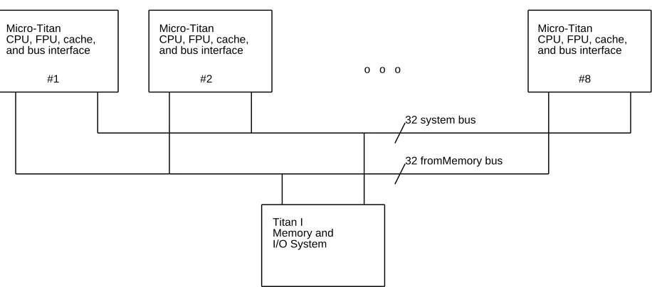
Each processor of MultiTitan is similar in many resects to the ECL Titan, but different in several others. MultiTitan is not object code compatible with the ECL Titan. Like the ECL Titan, it is a very simple RISC machine with a branch delay of one. Unlike the ECL Titan, the MultiTitan has hardware support for small-grain parallel processing, vector floating point registers and operations, and a different pipeline and method for handling exceptions. Figure 1-1 is an overview of one MicroTitan processor, while Figure 1-2 illustrates a MultiTitan system consisting of eight MicroTitan processors.
10 CPU Op & RR|RA
64 data 32 address
32 system bus Memory System
Interface (TTL and ECL latches and buffers) CCU chip (custom VLSI)
512 entry TLB FPU chip
(custom VLSI)
32 fromMemory bus CPU chip
(custom VLSI)
2KB I-Buffer
22 16Kx4 25ns External Cache RAMs
64KB Data 64KB
Instr.
Figure 1-1: Block Diagram of One MicroTitan Processor
o o o
#8 #2
#1
Micro-Titan CPU, FPU, cache, and bus interface
Titan I Memory and I/O System
32 system bus
32 fromMemory bus
Micro-Titan CPU, FPU, cache, and bus interface Micro-Titan
[image:10.612.67.525.72.274.2]CPU, FPU, cache, and bus interface
Figure 1-2: MultiTitan System Block Diagram
The CCU handles virtual to physical address translation, interface to I/O devices, low overhead processor to processor communication, interactions with the memory system, and control of the cache during CPU memory references. It provides support for software control of shared data, as opposed to hardware control of shared data (e.g., a snoopy bus). In direct mapped caches (where data store and tag store are implemented with the same speed RAMs), provisional data is available a significant amount of time before hit or miss is known. The CPU takes advantage of this property; it starts using the data a cycle before hit or miss is required from the CCU. Similarly, page faults are not known until after the data may have been written back into the register file. Thus, when a memory reference page faults, the instruction is allowed to complete in error before an interrupt occurs. Kernel software resumes execution with the instruction that caused the page fault. Note that this requires all memory references to be idempotent. The details of virtual address translation are orthogonal to the CPU chip itself. Please consult the CCU specification for details.
The floating point coprocessor performs G-format double precision (64 bit) floating point addition, subtraction, multiplication, reciprocal approximation, conversion to and from integer, and single precision (32 bit) integer multiplication. These operations take place concurrently with normal instruction processing of the CPU, except that the CPU and CCU wait for completion of operations when they need a result from the coprocessor. The FPU has 52 general purpose registers, and supports vector arithmetic operations. The CPU chip is the only chip to generate memory addresses. In coprocessor loads and stores the CPU chip generates addresses as if it were a load or store of its own register file, but ships the register address to the coprocessor. The coprocessor then either latches or sends out the data.
L o g o s Pad con-trol dri-vers PC Queue, PC Incr., + misc.
Instruction Decode, Pipeline Control, and Data Path control line drivers
Instruction bus D e c o d e r s a n d d r i v e r s C l o c k s
Data and Address Pads
Data and Address Pads 6.8 mm
Scale: 1/2" = 0.75mm in CMOS-2 C o n t r o l a n d E x t e r n a l I n t e r f a c e P a d s 8.7 mm D a t a a n d A d d r e s s P a d s Data Write Logic
[image:11.612.119.461.86.526.2]Sense amps and comparators 512 instructions Direct mapped 4 words per line Instruction Buffer Register File (48 GPR’s) B y p a s s A L U S h i f t e r
Data Data
Parity Checker Parity
Gener-ator R
A,W B
P S W P
C
RR|RA CPU Op
External Cache memory access Address "0"
+1
IR[ALU] IR[MEM] IR[WB]
WB
512 words Direct mapped 4 word lines On-chip Instruction
Buffer Register File (48 GPR’s) W
W
disp
MEM ALU
Logical Unit Shift + Extract Adder/ Subtractor IF
[image:12.612.37.567.107.488.2]B A
2. Instruction Set Architecture
Several overriding concerns determined the encoding of the instruction set.
First, in order for instruction source registers to be fetched in parallel with decoding of the opcode, the register sources must be in one and only one position in all instructions. Since store instructions read their operand to be stored at the same time as loads write their target, and arithmetic operations write their destination at the same time as loads, both store sources, load destinations, and arithmetic destinations must be in the same place. Some instructions, like add immediate, have only one register source and destination, so this constrains one source and the destination register to be specified by the high order halfword, since the displacement is in the low order halfword. As in the ECL Titan, there is enough encoding space for 64 registers (although only 48 GPR’s are implemented). With a four bit opcode we will neatly use the upper halfword: the opcode resides in the highest four bits, followed by the destination (rr) and the first source (ra).
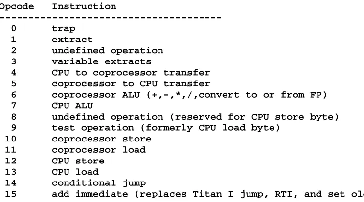
Second, the opcode should be trivial to decode. Thus, the instruction opcodes are arranged so that one or two bits determine most functions. For example, all instructions with 16 bit displacements have as their highest bit "1". As another example, all the instructions with a valid destination register can be covered with two boolean n-cubes. The encodings are given in Figure 2-1.
Opcode Instruction
---0 trap
1 extract
2 undefined operation 3 variable extracts
4 CPU to coprocessor transfer 5 coprocessor to CPU transfer
6 coprocessor ALU (+,-,*,/,convert to or from FP) 7 CPU ALU
8 undefined operation (reserved for CPU store byte) 9 test operation (formerly CPU load byte)
10 coprocessor store 11 coprocessor load 12 CPU store
13 CPU load
14 conditional jump
[image:13.612.97.469.304.511.2]15 add immediate (replaces Titan I jump, RTI, and set oldpc)
Figure 2-1: MultiTitan Instruction Opcodes
2.1 CPU Registers
CPU registers are named r0 through r63. The expression "rx" refers to the contents of the register whose number is encoded in the rx field of the current instruction, where rx is either ra, rb or rr. There are two instruction formats, illustrated in Figure 2-2.
|< 4 >|< 6 >|< 6 >|< 6 >|< 10 >| +---+---+---+---+---+ |opcode | rr | ra | rb | miscellaneous | +---+---+---+---+---+ |< 4 >|< 6 >|< 6 >|< 16 >| +---+---+---+---+
|opcode | rr | ra | displacement |
+---+---+---+---+
Figure 2-2: Instruction Formats
PSW as a destination, since it is write-only, will also have no effect. Thus the recommended No-op is "PSW := PSW op PSW", where op is any ALU or shift operation.
Number Name Restrictions
---63 PC Only for rr in ALU or add imm, ra in all instructions 62 PSW Only for rb in ALU or var byte (it is read only) 61 PCQE Only for rb in ALU or var byte, rr in ALU or add imm 60 PCQ Only for rb in ALU or var byte, rr in ALU or add imm 59-48 reserved for future use
Figure 2-3: CPU Special Registers
PCQ is a queue of four address: IFpc, ALUpc, MEMpc, and WBpc. When the processor is not in kernel mode, successive values of the pc enter the queue. When a trap occurs, WBpc contains the pc of the instruction which was in its WB pipestage, MEMpc the next instruction, ALUpc the third, and IFpc the address of the instruction in its IF pipestage. If nil instructions are inserted into the pipeline as a result of interlocks or instruction buffer misses, the nil instructions have the same pipestage pc as the next valid instruction in the pipeline. For example, if WBpc, MEMpc, and ALUpc all contain the same value, only ALUpc refers to a valid instruction. Reading PCQ reads WBpc, while writing it writes IFpc. Note that since instruction PC’s are duplicated by interlocks or instruction buffer misses, WBpc cannot be used in user mode as the address of a previous instruction. Reading PCQE (PCQExit) reads WBpc, but has the side effect of exiting kernel mode after a branch delay of one instruction.
2.2 Coprocessor Registers
Coprocessors share a 6 bit register address space; the registers are named c0 through c63.
The FPU has 52 GPR’s and 3 special registers: FPU PSW, time-of-day clock, and interval timer. They are addressed 0 to 54. The special registers can only be accessed by coprocessor load and store instructions; when accessed by FPU ALU instructions they return the constants 0, 1/2, and 1.
Function
---Flush cache line
Clear cache line
Test and set line in main memory I/O operations
Load/store another processor’s cache Load/store CCU PSW
Load/store TLB fault register
Load/store TLB tag (set 1 through 4) Load/store TLB data (set 1 through 4)
2.3 Instructions
For each instruction, we list its name, its assembly language form, its memory format, and a brief description of its operation. The syntax for the Titan assembler has been extended to provide for the MultiTitan. Note that c0 - c63 denote the coprocessor registers, .. and .: denote variable extracts (bit field and byte respectively).
2.3.1 Trap
TASM Format
trap literal
Memory Format
|< 4 >|< 28 >|
+---+---+
| | |
| 0 | Optional trap literal |
| | |
+---+---+
This instruction causes a trap (i.e., software interrupt) in user mode. During kernel mode it is a No-op. The interrupt is asserted duing the instruction’s WB pipestage. The optional trap literal is not saved in any CPU register but must be obtained by examining the instruction itself.
Example: trap;
2.3.2 Extract Field
TASM Format
rr := ra,rb.[size, pos];
Memory Format
|< 4 >|< 6 >|< 6 >|< 6 >|< 5 >|< 5 >| +---+---+---+---+---+---+
| | | | | | |
| 1 | rr | ra | rb | size | position|
| | | | | -1 | |
+---+---+---+---+---+---+
Registers ra and rb are concatenated to form a 64 bit word, with ra on the left. A contiguous field is extracted from this quantity, right justified and zero-extended to 32-bits, and stored in register rr.
Field extraction is accomplished by right shifting rb by the value in the position field, filling in the high order bits from ra. Thus a zero in this field implies that rb will appear unshifted in the result, while 31 in the position field implies that most significant bit of rb will be the least significant bit of the result, and all but the most significant bit of ra will appear in the upper 31 bits of the result.
The size of the extracted field is one greater than the value in the size field of the instruction; e.g. zero in the size field of the instruction causes a single bit to be extracted, while 31 in the size field obtains a 32-bit result.
Examples:
r3 := r4,r4.[0,31]; /* puts sign bit of r4 in r3 lsb */ r3 := r10,r10.[31,4]; /* rotates r10 right by 4 */
2.3.3 Undefined Operation
TASM Format
no TASM format
Memory Format
|< 4 >|< 28 >|
+---+---+
| | |
| 2 | |
| | |
+---+---+
This instruction causes an unpredictable operation. It will not cause an illegal instruction opcode trap, since there is no such trap. However, it may cause a privilege violation, write a register, or write a memory location, but its operation is unknown and implementation dependent. This instruction should never be generated.
2.3.4 Variable Extract
TASM Format
rr := (ra,rb)..[size]; rr := (ra,rb)..-[size];
rr := (ra,rb).:[size]; (byte ref) rr := (ra,rb).:-[size]; (byte ref)
Memory Format
|< 4 >|< 6 >|< 6 >|< 6 >|< 5 >|<2>|1|1|1| +---+---+---+---+---+---+-+-+-+
| | | | | | |N|-| |
| 3 | rr | ra | rb | size | |*|N| |
| | | | | -1 | |8| | |
+---+---+---+---+---+---+-+-+-+
A field extract is performed with the position field taken from the least significant 5 bits of the contents of ra. Note that ra is used both as the high order word of the field to be selected from, and as the position count. This position is interpreted according to the N*8 and -N bits. If the -N bit is on, the position is complemented (e.g., in a right bit shift of 30 becomes a right shift of 1). This results in a big endian (i.e., IBM order, where the most significant bit is numbered 0) variable shift being performed. If the -N bit is off, then a little endian right shift is performed (i.e., VAX order, where the most significant bit is numbered bit 31). If N*8 is on, then the position is shifted left 3 bits and filled with zeros. This results in a variable byte right shift. Both the N*8 and -N bits may be asserted at the same time, in which case a big endian byte shift results.
The size of the extracted field is one greater than the value in the size field of the instruction; e.g. zero in the size field of the instruction causes a single bit to be extracted, while 31 in the size field obtains a 32-bit result.
if (-N)
then pos = ~ra else pos = ra if (N*8)
then pos = 8 *(pos mod 4) else pos = pos mod 32 lbit = 32 + pos - size rbit = 32 + pos.
Examples:
r2 := r3,r4.[0]; /* one bit */
r2 := r3,r4.-[0]; /* one bit, reversed ordering */ r2 := r3,r4.:[7]; /* one byte */
2.3.5 CPU to Coprocessor Transfer
TASM Format
ca := rr;
Memory Format
|< 4 >|< 6 >|< 6 >|< 16 >| +---+---+---+---+
| | | | |
| 4 | rr | ca | |
| | | | |
+---+---+---+---+
Rr is a CPU register, ca is a coprocessor register. The CPU performs a store instruction, but the CCU does not enable the memory. The CPU outputs rr onto the high order data lines during its WB pipestage (i.e., word "1"). A coprocessor writes the high order word of register ca with the data, and the low order half of register "ca" becomes undefined. This instruction is useful for transferring operands to the FPU for integer multiplies. The register address "ca" plus the opcode are transferred to the coprocessors in the ALU pipestage.
2.3.6 Coprocessor to CPU Transfer
TASM Format
rr := ca;
Memory Format
|< 4 >|< 6 >|< 6 >|< 16 >| +---+---+---+---+
| | | | |
| 5 | rr | ca | |
| | | | |
+---+---+---+---+
Rr is a CPU register, ca is a coprocessor register. The CPU performs a load instruction, but the CCU does not enable the memory. A coprocessor outputs the high order word of ca onto the high order data lines (i.e., word "1"). The CPU reads the data at the beginning of its WB pipestage. This is useful for obtaining results from the FPU for integer multiplies. It is also used to transfer the result of FPU comparisons to the CPU for testing by conditional branches. If the coprocessor register specified by ca is not yet available due to a computation in progress, the coprocessor will deassert LoadWB until it can output the result. The register address "ca" plus the opcode are transferred to the coprocessors in the ALU pipestage. This instruction cannot appear in the branch delay slot of any
2.3.7 Coprocessor ALU
TASM Format
cr := ca(ALU)cb;
Memory Format
|< 4 >|< 6 >|< 6 >|< 6 >|< 10 >| +---+---+---+---+---+
| | | | | |
| 6 | cr | ca | cb | function |
| | | | | |
+---+---+---+---+---+
A coprocessor performs an ALU operation. The CPU ships the coprocessor the entire instruction over the address lines during its unused mem pipestage. Please consult the FPU architecture document for more details about this instruction.
2.3.8 CPU ALU
TASM Format
rr := ra op rb;
Memory Format
|< 4 >|< 6 >|< 6 >|< 6 >|< 5 >|< 4 >|1| +---+---+---+---+---+---+-+
| | | | | | |l|
| 7 | rr | ra | rb | function| unit |i|
| | | | | | |t|
+---+---+---+---+---+---+-+
The ALU performs boolean or arithmetic operations on the A and B operands, storing the result in register rr. The B operand is register rb. The A operand is register ra if the literal select bit is clear, otherwise it is the ra field of the instruction, zero-extended to 32 bits. The unit field selects a functional unit. Codes with more than one bit set (and hence more than one unit selected) produce the logical AND of the results of the selected units. The unit codes are:
0: all one’s 1: add and sub 2: comparisons
4: logical (boolean) 8: reserved
The function is interpreted depending on the unit specified. The first tables below specify the logical operations performed by each functional unit and how they are encoded. Subsequent tables and information provide implementation specific description of how the functional units work. If checks for arithmetic overflow are enabled, and an arithmetic overflow occurs, then an overflow trap is generated during the instruction’s WB pipestage.
Add and Subtract: Function Field Value Operation
---0xxV0 a+b xx denotes 2 "don’t care" bits. 1xxV1 b-a V=1 specifies trap on overflow 0xxV1 a+b+1
Logical: Function Field
(Most significant bit of field doesn’t matter) Hex Value Operation ---8 and 1 nor E or 6 xor
A B bus C A bus
9 eqv
5 not B 3 not A 0 False (0) F True (1) 2 B and (not A) 4 A and (not B) 7 not (A and B)
B (not A) or (A and B) => not (A and not B) D (not B) or (A and B) => not (B and not A) Comparison: Function Field
(Most significant bit must be 1) Hex
Value Operation ---1A a <u b \
1B a <=u b \ unsigned 15 a >u b / comparisons 14 a >=u b /
1E a < b \
1F a <= b \ signed 11 a > b / comparisons 10 a >= b /
Add and subtract function encoding:
(msb and lsb both on for subtract, both off for add) msb: complement A src
(don’t care) (don’t care)
trap if overflow detected lsb: carry in
Logical function encoding:
results for each bit in the data path (0<=i<=31): msb: (don’t care)
output[i] if A[i]B[i]=11 output[i] if A[i]B[i]=10 output[i] if A[i]B[i]=01 lsb: output[i] if A[i]B[i]=00
A B Y |\ output if AB=11 -| |
output if AB=10 -| |_ output output if AB=01 -| |
output if AB=00 -| | |/
Comparison instructions set the sign bit of rr to 1 if the relation is true, 0 otherwise. The value of the other bits in rr is 1. The compares denoted with a trailing u are unsigned compares, the others are signed compares. Note that there is no ra <> rb or ra = rb instruction. There are four input control lines for comparisons. They are determined by consulting the table below. "S" is the sign of the resulting sum of rb-ra. B[msb] is the sign bit of rb. The comparisons are chosen by specifying the sense of the result for each combination of A[msb] and B[msb] and by providing the carry in. A sense of "1" implies the value in the table (e.g., "S") is complemented.
Comparison function encoding:
msb: must be 1 (for subtract)
sense of result if A[msb],B[msb] = {1,1}
sense of result if A[msb],B[msb] = {0,1} or {1,0} sense of result if A[msb],B[msb] = {0,0}
lsb: carry in
Function is A cond B
2.3.9 Undefined Operation (Reserved for CPU Store Byte)
TASM Format
no TASM format
Memory Format
|< 4 >|< 28 >|
+---+---+
| | |
| 8 | |
| | |
+---+---+
This instruction causes an unpredictable operation. It will not cause an illegal instruction opcode trap, since there is no such trap. However, it may cause a privilege violation, write a register, or write a memory location, but its operation is unknown and implementation dependent. This instruction should never be generated.
2.3.10 Test Operation (Formerly CPU Load Byte)
TASM Format
? TASM format
Memory Format
|< 4 >|< 28 >|
+---+---+
| | |
| 9 | |
| | |
+---+---+
2.3.11 Coprocessor Store
TASM Format
(disp[ra]) := cr;
Memory Format
|< 4 >|< 6 >|< 6 >|< 16 >| +---+---+---+---+
| | | | |
| 10 | cr | ra | word displacement |
| | | | |
+---+---+---+---+
An address is computed by left shifting the displacement field of the instruction by two bits, sign-extending it to 32 bits, and adding register ra. The three low-order bits of the address are ignored (i.e., assumed zero) and register cr of the coprocessor is stored into the 64-bit doubleword at that address. The register address "cr" plus the opcode are transferred to the coprocessors in the ALU pipestage.
2.3.12 Coprocessor Load
TASM Format
cr := (disp[ra]);
Memory Format
|< 4 >|< 6 >|< 6 >|< 16 >| +---+---+---+---+
| | | | |
| 11 | cr | ra | word displacement |
| | | | |
+---+---+---+---+
2.3.13 CPU Store
TASM Format
(disp[ra]) := rr;
Memory Format
|< 4 >|< 6 >|< 6 >|< 16 >| +---+---+---+---+
| | | | |
| 12 | rr | ra | word displacement |
| | | | |
+---+---+---+---+
An address is computed by left shifting the displacement field of the instruction by two bits, sign-extending it to 32 bits, and adding register ra. The two low-order bits of the address are ignored (i.e., assumed zero) and register rr is stored into the 32-bit word at that address. Stores probe the external cache in the MEM pipestage, and send out data to the cache in WB. If a hit has been detected during the probe, the CCU enables writing from the data bus into the RAMs in the second half of the WB pipstage. Interactions with other instructions will be discussed in the timing section.
Example: -3[r4] := r5;
2.3.14 CPU Load
TASM Format
rr := (disp[ra]);
Memory Format
|< 4 >|< 6 >|< 6 >|< 16 >| +---+---+---+---+
| | | | |
| 13 | rr | ra | word displacement |
| | | | |
+---+---+---+---+
An address is computed by left shifting the displacement field of the instruction by two bits, sign-extending it to 32 bits, and adding register ra. The two low-order bits of the address are ignored (i.e., assumed zero) and the 32-bit word at that address is loaded into register rr. Ra and rr should not be the same or else this instruction is not
2.3.15 Conditional Jump
TASM Format
if ra cond goto disp
Memory Format
|< 4 >|< 6 >|< 6 >|< 16 >| +---+---+---+---+
| | | | |
| 14 | cond | ra | word displacement |
| | | | |
+---+---+---+---+
An address is computed by left shifting the displacement field of the instruction by two bits, sign-extending it to 32 bits, and adding the pc (the address of the conditional jump instruction). This address is loaded into pc if register ra meets the condition specified by the cond field (otherwise the pc increments normally). This results in a conditional transfer of control to the instruction at the computed address, following execution of the next instruction in line. Note that this instruction requires implicit addressing of the pc (the only such case). It is also the only instruction with three sources: ra, pc, and displacement. The instruction after the branch is always executed.
The table below details the "cond" values for the conditional jump instruction. Following this table there is more information of an implementation nature that details how the conditional jump gets decoded by the MultiTitan.
Conditional Jump Values
(The two highest order bits of the cond field are ignored Note that all comparisons are made against "zero".)
value utasm
---0 always goto disp
1 never goto disp 5 if ra < goto disp 6 if ra = goto disp 7 if ra <> goto disp 3 if ra > goto disp 2 if ra <= goto disp 4 if ra >= goto disp
9 if ra % goto disp (if ra odd goto disp) 8 if ra & goto disp (if ra even goto disp)
The condition is the logical NOR of up to three selected bits: the lsb, the sign bit, and a bit which is true if the word is greater than zero. If the sense bit is on, then the condition is true if the logical OR of the selected bits is one. For example, equality to zero can be tested for by selecting >0 and <0.
COND(ra) is:
msb: unused unused select lsb select <0 select >0 lsb: sense of OR
2.3.16 Add Immediate (or Load Address, or ..)
TASM Format
rr := ra + disp; or goto disp[ra];
Memory Format
|< 4 >|< 6 >|< 6 >|< 16 >| +---+---+---+---+
| | | | |
| 15 | rr | ra | word displacement |
| | | | |
+---+---+---+---+
An address is computed by left shifting the displacement field of the instruction by two bits, sign-extending it to 32 bits, and adding register ra. The result is stored in register rr. Note that assignments to the PC take effect after executing the next instruction. Add immediate can be used to synthesize many other instructions, but since the displacement is shifted by two bits it can only add or subtract multiples of four.
Examples:
r33:= pc + 2; /* subroutine call, part 1 */ pc := pc - 1025; /* subroutine call, part 2 */
3. Exception Architecture
As well as having a simplified instruction set, MultiTitan also has a simplified exception architecture. For example, interrupts, page faults, coprocessor traps, and bus error are all signalled by pulling down a common interrupt line in the cycle after the exception. But before individual exceptions and trap handling is described in detail, we must first examine the pipeline and its timing.
3.1 Pipeline Timing
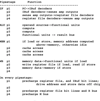
The MultiTitan CPU has a four stage pipeline. The stages are instruction fetch (IF), compute (ALU), memory access (MEM), and result write back (WB). A description of the actions taken in each pipestage is given in Figure 3-1. Each pipestage is broken into four clock phases. One and only one of the clock phases is high at all times, subject to small amounts of skew which may result in zero or two clock phases being high for a few nanoseconds. In the following discussions, store instruction will be used generically to refer to CPU store, coprocessor store, and CPU->coprocessor transfer, which all use the data and/or address busses in the WB stage. Load instruction will be used to refer to CPU load, coprocessor load, coprocessor->CPU transfer, and coprocessor ALU instructions, which all use the data and/or address busses in the MEM pipestage.
Pipestage Function
---IF p1 PC->IBuf decoders
p2 IBuf decoders->sense amp outputs
p3 sense amp outputs->register file decoders p4 register file decoders->sense amp outputs ALU p1 operand sources->functional units
p2 compute p3 compute
p4 functional units -> result bus
MEM p1 if load or store, memory address computed above->memory, otherwise idle p2 cache access
p3 cache access p4 cache access
WB p1 memory data->functional units if load p2 write register file if load, read if store p3 memory data->memory if store
p4
On every pipestage:
p1 precharge register file, and IBuf bit lines; drive address and store data off chip p2
[image:29.612.97.442.291.638.2]p3 precharge register file bit lines and R bus p4 precharge M bus
Figure 3-1: Pipeline Phase-by-Phase Timing
In the absence of exceptional conditions, one instruction is issued every cycle (40 nsec). All instructions commit in their WB pipestage; this implies if an instruction causes an interrupt it can only do so in WB.
Store Interlock If the instruction following a store class instruction is a load class or store class instruction, one cycle is lost.
Coprocessor->CPU Transfer Interlock
If a Coprocessor->CPU transfer instruction follows a coprocessor load or store, one additional cycle is lost.
CPU->Coprocessor Transfer Interlock
If a Coprocessor->CPU transfer instruction attempts to issue two cycles after a CPU->Coprocessor transfer, one additional cycle is lost. Note that if a CPU->Coprocessor transfer is followed immediately by a Coprocessor->CPU transfer, a store interlock will occur on the first attempted issue of the Coprocessor->CPU transfer, and then the CPU->Coprocessor transfer interlock will occur, increasing the spacing between the two transfers to three.
Instruction Buffer Miss
Any instruction fetch which misses in the instruction buffer will incur at least a two cycle delay, assuming a hit in the external instruction cache. An instruction buffer miss that occurs while a store is in its MEM stage will be delayed one additional cycle. If the missing instruction is on word 3 of the line, or if there is a taken branch in the ALU pipestage, one additional delay cycle will occur at the end of an instruction buffer miss.
External Cache Miss
A load, store, or instruction buffer miss which misses in the external cache results in a delay of 14 cycles. If a load or store instruction immediately follows a load or store instruction that misses, one extra delay cycle will occur.
Coprocessor Stall Wait for completion of the coprocessor can cost up to 48 cycles.
Trap or Interrupt Any trap condition costs a three cycle delay until the instruction at the location specified by the upper 28 bits of PSW is executed. This will be followed by a further delay because the I-buffer will miss (since it is cleared on all context switches).
3.2 Program Status Words
Although page faults, coprocessor traps, and bus errors are all signalled via the same interrupt pin, these conditions are differentiated by program status words (PSW’s) in each of the CPU, CCU, and FPU. Figure 3-2 gives the format of the CPU PSW. It is read only and reading it is not privileged.
|< 23 >|1|< 3 >|1|1|1|1|1| +---+-+---+-+-+-+-+-+
| zero |S|PrId |B|T|V|K|P|
+---+-+---+-+-+-+-+-+
Figure 3-2: CPU PSW format
The B bit is on if the processor is being booted. It is generated internally from the CPU by delaying the Reset input. The PrId field is the hardware processor id. It is directly connected to three external pins and can range from 0 to 7. During boot sequences the upper 28 bits of the PSW (the other bits are zero) is used as a base address; the PrId field allows different processors to execute different code. The PrID field is placed in the PSW so that different processors will execute different cache lines. The S bit is on if the processor is being booted and is requested to save its state before booting. The S bit is a chip input, and is driven from the clock/scan board.
The T bit is ’1’ if a software trap occurred when the last interrupt was taken. The V bit is ’1’ if an instruction having an arithmetic overflow trap was in its WB pipestage when the last interrupt was taken. The K bit is ’1’ if the instruction in the IF pipestage is in kernel mode. In Kernel mode all interrupts are disabled and privileged instructions are enabled. The P bit is ’1’ if a hard parity error occurred in the cycle before the interrupt.
3.3 Pipeline Advancement
There are seven possible ways in which the pipeline advances from one cycle to the next. Figure 3-3 lists them in increasing order of priority. There are also eight control lines which determine pipeline advancement either directly or indirectly: LoadIF (internal to CPU), LoadALU, LoadMEM, LoadWB, AllowInterrupt, Interrupt, Reset, and Kernel.
1) Normal pipeline advance: WB := MEM;
MEM := ALU; ALU := IF; IF := PC + 4;
2) Branch taken pipeline advance: WB := MEM;
MEM := ALU; ALU := IF;
IF := Branch target;
3) Interlock (LoadIF deasserted; LoadALU, LoadMEM, and LoadWB are not) WB := MEM;
MEM := ALU;
ALU := NIL; delay slot injected here IF := Recirculate;
4) IBuf miss (LoadALU deasserted; LoadMEM and LoadWB are not): WB := MEM;
MEM := IBM refill; a load class instr ALU := Recirculate; ALU does not advance IF := Recirculate;
5) Memory Reference Retire (LoadMem deasserted, LoadWB is not): WB := NIL;
MEM := Recirculate; ALU := Recirculate; IF := Recirculate;
6) LoadWB deasserted (i.e., "stall"): WB := Recirculate;
MEM := Recirculate; ALU := Recirculate; IF := Recirculate;
7) Interrupt: (Interrupt and AllowInt asserted, or Reset asserted) WB := NIL;
MEM := NIL; ALU := NIL;
IF := PC = PSW[31..4];
8) Uninterruptible Stall (LoadWB and AllowInterrupts deasserted): WB := Recirculate;
[image:32.612.91.502.127.693.2]MEM := Recirculate; ALU := Recirculate; IF := Recirculate;
Figure 3-3: Pipeline Advancement
advance signal for a later pipestage is deasserted, the advance signals for all previous pipestages must be stalled as well. This is required so that instructions don’t overtake (i.e., crash into each other) in the pipeline. For example, if LoadMEM is deasserted, LoadALU and LoadIF must be deasserted as well. (Since the LoadIF signal only exists inside the CPU, it deasserts LoadIF internally when it sees LoadALU deasserted.)
If all signals have their load signal asserted, there is no interrupt, and the instruction in ALU is not a taken branch, all pipestages advance and the new IFpc is IFpc+4 (case 1). If an unconditional branch or a taken conditional branch is exiting its ALU pipestage, all signals have their load signal asserted, and there is no interrupt, then the branch target specified by the branch in ALU is the next IFpc (case 2). An interesting variation on this appears in the case of interlocks (case 3). In an interlock, LoadIF is deasserted, but all the other pipeline advance signals are asserted and there is no interrupt. If a taken branch instruction is in ALU during an interlock, it must advance since LoadALU and LoadMEM are asserted. However, the branch target cannot be immediately loaded into the IF pipestage since the interlock mandates that the instruction in IF be held. Thus interlocks are not allowed if a taken branch is in ALU. The only way to generate an interlock in IF concurrent with a taken branch in ALU is with a CPU->Coprocessor transfer followed by a taken branch with a Coprocessor->CPU transfer in the branch delay slot. This code sequence should never be generated or else unpredictable operation may result.
In the IBuf miss sequence (case 4) the ALU pipestage must not advance into MEM and thereby use the address pins. The IBuf miss sequence usually occurs for two cycles, but may require an additional cycle at the start of the sequence if a store class instruction is in Mem when the IBuf misses. During an instruction buffer miss, a total of two load-class pseudo instructions are inserted into the MEM pipestage in successive non-stall cycles. The first loads the requested doubleword into the cache line and the second loads the non-requested doubleword. The additional cycle delay that occurs when the instruction buffer misses with a store in the MEM pipestage is just a special case of the store interlock. An additional cycle is required at the end of the sequence if the next instruction is not on the same cache line. This is determined (slightly pessimistically) in the miss cycle by checking if the miss instruction is at word 3 of a cache line or if a taken branch is in the ALU pipestage. (In reality, the branch could be to the same cache line, and no extra cycle would be required.) The next instruction must be on the same line as the miss instruction so that the non-requested doubleword of the buffer line can be written into the buffer.
During stalls LoadWB and all earlier Load signals are deasserted (case 6). This results in all pipestages being stalled. If LoadMem is deasserted during an external cache miss but LoadWB is not, this signifies the requested data is on the data bus, and the instruction in WB should be retired (case 5). However, the following instructions may not advance until the memory operation completes.
If Interrupt and AllowInt (allow interrupt) are asserted, an interrupt is taken (case 7). AllowInt (and all the pipeline Load signals) may be deasserted during phase 3 if the CCU is in the process of a memory transaction. Thus AllowInt disables the effects of the Interrupt signal (case 8). To prevent exceptions from being handled, interrupts are ANDed with AllowInt. Inside the CPU the External Reset signal is OR’ed with the result of the AND’ing of AllowInt and Interrupt. Thus, reset has the same effect as an enabled interrupt, except that reset should be asserted at least 7 cycles so that all pipeline state can be reset. Although interrupt receivers must check AllowInt to tell if an interrupt is valid, interrupt sources must check the Kernel signal before generating interrupts. Interrupts should never be asserted in kernel mode, since if it is taken the return addresses will not have been saved in the PCQ.
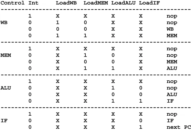
Control Int LoadWB LoadMEM LoadALU LoadIF
---1 X X X X nop
WB 0 1 0 X X nop
0 0 0 X X WB
0 1 1 X X MEM
---1 X X X X nop
MEM 0 X 1 0 X nop
0 X 0 0 X MEM
0 X 1 1 X ALU
---1 X X X X nop
ALU 0 X X 1 0 nop
0 X X 0 0 ALU
0 X X 1 1 IF
---1 X X X X nop
IF 0 X X X 0 IF
0 X X X 1 next PC
---Figure 3-4: Operation of Each Pipestage
3.4 Interrupts
Upon any of a set of special circumstances, the processor interrupts the normal sequence of instruction execution, sets the program status word to kernel mode (interrupts disabled, privileged instructions enabled), disables address translation, and forces the upper 28 bits of the PSW as the new PC. In addition it sets bits in the program status word indicating if a trap instruction or arithmetic overflow was one cause of the interrupt (there may be more than one cause). If an interrupt occurs in kernel mode, the processor follows these same steps. However, since in kernel mode the PCQ does not advance, no record of the trap PC will be saved. Thus, all interrupt generators must check the Kernel bit and only generate interrupts if the Kernel bit is off.
3.4.1 Determining Instructions in Progress
[image:34.612.95.426.71.301.2]Code sequence 51: r1 := 0[r2]; 52: r3 := r1 + r7; 53: pc := pc - 43; 54: r4 := 2[r3];
time ->
PCQ Sequence 1 2 3 4 5 6
WBpc - - - 51 52 52
MEMpc - - 51 52 52 53
ALUpc - 51 52 52 53 54
pc in IF 51 52 52 53 54 10
Figure 3-5: Operation of the PC Queue during Load Interlock
3.4.2 Parity Errors and Interrupts
The MultiTitan chip set maintains parity on its 64-bit local data bus. This parity is odd byte parity. Checking of parity is controlled by the CheckParity signal, output by the CCU from its PSW. On all CPU load and Cop->CPU transfer instructions the CPU checks the parity of the word written into its register file (see Figure 1-4). If the parity is incorrect, and CheckParity is asserted, the CPU asserts interrupt in the following cycle (assuming AllowInt is asserted). Thus, the parity error is associated with the instruction before the instruction recorded in WBpc (unless a stall was in progress with AllowInt asserted at the time of the interrupt). Since the values of LoadWB at the time of the interrupt is not saved, the instuction causing the parity error can not be determined precisely, and is usually not even one of the instructions in the PCQ. But hard parity errors are not restartable in software anyway, so this impreciseness is of little consequence except to diagnostic programs.
The CPU places proper parity on the driven word of the data bus in CPU stores and CPU->Cop transfers. In order to drive the parity bits at the same time as the data bits, the parity bits must be available when the data is read out of the register file (i.e., the parity bits must be stored in the register file too.) Data is written into the register file from two sources: the local data bus, or a functional unit within the CPU (e.g., ALU, barrel shifter, and compare unit). The local data bus has parity; to provide proper parity in the case of results of CPU functional unit results written into the register file, parity is computed on the R bus during the ALU, shift or extract instruction’s normally idle MEM stage. On each write of the register file the parity of the written word is checked. This checks incoming data in the case of a CPU load-class instruction, and also checks the parity generator in the case of a CPU ALU, shift, or extract instruction. Since parity is stored in the register file, parity errors in the register file as well as the external data busses and data cache can also be detected. However, since the CPU does not check the parity of operands read out of the register file, a parity error in the register file is only detected if the erroneous register is written back to main memory or is written into the data cache and loaded back into the register file.
during the write of the requested word in an instruction buffer miss refill sequence, the error is assumed to be in the data busses or external instruction cache; if CheckParity is asserted the CPU asserts interrupt in the following cycle.
A parity error could also occur in two cases during an instruction buffer miss refill sequence on the instruction following the instruction causing a miss. If the following instruction is in the same doubleword as the missing instruction, it will be written into the instruction buffer at the same time as the missing instruction, and when it is read it will be read from the RAM cells instead of from the bypass path. A parity error in this case could originate either in the instruction buffer of in external circuits. If the following instruction is in the non-requested doubleword, when it is read it will read from the bypass path. A parity error in this case would be independent of the instruction buffer RAM array (i.e., it would probably originate externally). Since these two cases are not distinguished, the CPU just forces a miss on a parity error on the instruction following a miss. Then if the parity error occurs on the refetch of the instruction from off chip, the error will occur during the write of the requested doubleword and will cause an interrupt (assuming AllowInt is asserted). Thus a bit cell error in the instruction buffer, whether transient or due to defects, will simply cause additional instruction buffer misses but will not prevent execution of programs. Up to one cell in every byte of every instruction in the instruction buffer may fail and the chip will still work (albeit more slowly).
3.4.3 Returning from an interrupt
In general, the last two uncommitted "valid instructions" must be restarted when returning from an interrupt. If the last valid instruction is in WB, it should only be restarted in the presense of page faults since in other circumstances the instruction in WB will have already committed. Note that in order to be restarted, load instructions cannot have ra=rr since they will have already written rr.
Although there may be as few as two valid instructions in the pipeline, there may be only one restartable instruction in the pipeline after an interrupt. This occurs in the case of a Coprocessor->CPU transfer that follows immediately after a CPU->Coprocessor transfer. The Coprocessor->CPU transfer instruction will have two successive interlocks. At this point, the address of the CPU->Coprocessor instruction will be in WBpc and the address of the Coprocessor->CPU transfer instruction will be in IFpc, ALUpc, and MEMpc. If an I/O interrupt occurs in this situation, the CPU->Coprocessor instruction in WB will not be restarted, which leaves only one valid instruction to restart. In there is only one valid PC in the PCQ, then there can be no pending branches, and the instructions specified by IFpc and IFpc+4 should be restarted.
Once the PC’s to be restarted have been found, they must be placed back into MEMpc and WBpc, with the first instruction to be restarted placed in WBpc. PCQ may be written by specifying it as the rr field in CPU ALU or add immediate instructions. The write will take place in the MEM pipestage; the PCQ is read in the ALU pipestage. Thus writes to the PCQ will commit one cycle earlier than other instructions, and reads will occur one cycle later. (But since all interrupts must be off to execute these instructions, we are safe.)
buffer fault, an interrupt will occur. However, if the TB fault was on the instruction access of the first restarted instruction, the PC queue will contain an undefined value in ALUpc (and hence also the same value in MEMpc and WBpc due to the instruction buffer miss). If after processing this exception, the values in ALUpc and IFpc were restarted, incorrect operation would result from the undefined address in ALUpc. Therefore for correct operation the first return PC must have a valid translation.
4. Interface Architecture
Figure 4-1 summarizes the CPU pin assignments. Pads for the two words in the data bus doubleword plus the address bus are three-way interleaved. Although an entire data bus doubleword may be read into the CPU, at most one data word is written from the CPU. Similarly, data pad drivers are only active during store instructions, and the address bus is not active when the data bus is active. Thus, since there are at most 8 pads between I/O power and ground pins, at most three of these will be active at the same time.
# of Pins Type Function
---64 I/O Data bus
8 I/O Data byte parity 32 O Address bus
1 O Iaddress
1 I address alternate doubleword (CCU -> CPU) 1 I check parity enabled
1 O user/kernel mode 1 I/O NotInterrupt 1 I AllowInterrupts 1 I/O LoadIF
1 I/O LoadALU 1 I/O LoadMem 1 I/O LoadWB
1 I enable data bus drivers (from CCU)
6 O Cr (or ca) register address for FPU and CCU 4 O Instruction opcode for FPU and CCU
3 I PrId
1 I SaveState 4 O phi1..4 output 1 I power-up reset
1 I Clock In
1 I/O Spare
--- ---136 signal pads used of 144 available
plus:
16 I/O Vdd
16 I/O GND
2 internal Vdd
[image:39.612.96.477.159.525.2]2 internal GND
Figure 4-1: CPU Pinout
Table of Contents
1. Introduction
1
2. Instruction Set Architecture
5
2.1 CPU Registers 5
2.2 Coprocessor Registers 6
2.3 Instructions 8
2.3.1 Trap 8
2.3.2 Extract Field 8
2.3.3 Undefined Operation 9
2.3.4 Variable Extract 9
2.3.5 CPU to Coprocessor Transfer 11
2.3.6 Coprocessor to CPU Transfer 11
2.3.7 Coprocessor ALU 12
2.3.8 CPU ALU 12
2.3.9 Undefined Operation (Reserved for CPU Store Byte) 15
2.3.10 Test Operation (Formerly CPU Load Byte) 15
2.3.11 Coprocessor Store 16
2.3.12 Coprocessor Load 16
2.3.13 CPU Store 17
2.3.14 CPU Load 17
2.3.15 Conditional Jump 18
2.3.16 Add Immediate (or Load Address, or ..) 19
3. Exception Architecture
21
3.1 Pipeline Timing 21
3.2 Program Status Words 22
3.3 Pipeline Advancement 24
3.4 Interrupts 26
3.4.1 Determining Instructions in Progress 26
3.4.2 Parity Errors and Interrupts 27
3.4.3 Returning from an interrupt 28
List of Figures
Figure 1-1: Block Diagram of One MicroTitan Processor 1
Figure 1-2: MultiTitan System Block Diagram 2
Figure 1-3: CPU Floorplan 3
Figure 1-4: CPU Pipeline and Machine Organization 4
Figure 2-1: MultiTitan Instruction Opcodes 5
Figure 2-2: Instruction Formats 6
Figure 2-3: CPU Special Registers 6
Figure 2-4: CCU Register Addresses 7
Figure 3-1: Pipeline Phase-by-Phase Timing 21
Figure 3-2: CPU PSW format 22
Figure 3-3: Pipeline Advancement 24
Figure 3-4: Operation of Each Pipestage 26
Figure 3-5: Operation of the PC Queue during Load Interlock 27
Norman P. Jouppi
Digital Equipment Corporation
Western Research Laboratory
100 Hamilton Avenue
Palo Alto, CA 94301
Version of 6 April 1988