Chiral nanoparticle assemblies: circular dichroism, plasmonic interactions,
and exciton effects
Alexander O. Govorov,
*
aYurii K. Gun’ko,
*
bJoseph M. Slocik,
*
cVal
erie A. G
erard,
bZhiyuan Fan
aand Rajesh R. Naik
cReceived 25th May 2011, Accepted 9th August 2011
DOI: 10.1039/c1jm12345a
The paper reviews recent progress on chiral nanocrystal assemblies with induced optical chirality and related circular dichroism. Many natural molecules and biomolecules are chiral and exhibit remarkably strong optical chirality (circular dichroism) due to their amazingly uniform atomic composition in a large ensemble. It is challenging to realize artificial nanoscale systems with optical chirality since the atomic structure of artificial nanostructures may not be always controlled or even known. Nevertheless, the artificial optical chirality has been accomplished and it is the main scope of this review. In particular, we discuss assemblies incorporating chiral molecules, metal nanocrystals, and
semiconductor quantum dots. Plasmon-induced and plasmon-enhanced circular dichroism effects appear in nanoscale assemblies built with metal nanocrystals, while excitonic and surface-states related phenomena are observed in semiconductor quantum dots conjugated with chiral molecules.
Introduction
Chirality and an associated circular dichroism effect are fasci-nating properties of many molecules and bio-molecules. In optical spectroscopy, the circular dichroism (CD) and rotatory dispersion methods are employed to detect subtle conformation changes of biomolecules.1,2The detection of conformation states
of proteins (a-helix, random coil, orb-sheet) is one impressive example. The importance of sensing of chiral states of molecules can also be seen from the fact that an essential part of modern drugs are based on chiral molecules and their chiral purity is often crucial.3 Chirality and a nonzero CD signal are only
present if a molecule has neither mirror-plane symmetries nor a centre of symmetry. Therefore, such a molecule can be found in two enantiomeric states. Such enantiomeric states (or enantio-mers) are mirror images of each other and have opposite hand-edness (or chirality). It is expected that different enantiomers of one molecule should react differently on different chiral states of light that are left- and right-handed circularly polarized photons. This property provides us with the opportunity to measure chirality of molecules using the optical CD method. However, if a molecule is present in both its enantiomeric states in equal amounts, the overall chirality of a solution vanishes and CD
signals are not observed anymore. Another important require-ment for observing a non-vanishing CD signal from a large ensemble of randomly-oriented microscopic objects is a high degree of homogeneity. In the case of molecules, this requirement is certainly satisfied since molecules and biomolecules of the same kind and chirality in a solution are amazingly uniform in composition. On the other hand that last requirement sets a challenge for the case of nanostructures - it seems impossible to control the positions of all atoms in a nanocrystal that has typically a large number of atoms. In fact, any nanocrystal is chiral since it has low symmetry due to bulk defects and the surface. However, nanocrystals in a macroscopic ensemble in a solution typically show no optical chirality (CD) for the reason that nanocrystals chirality is random. Nevertheless, chiral nanocrystals can be designed and fabricated and the purpose of this paper is to review latest results on this interesting and emerging topic.
Chiral nanostructures can be constructed using metal nano-crystals (Sections 1.1 and 1.2) or semiconductor quantum dots (Section 2) and, in many cases, a chiral molecule is an important element of chiral nanostructure. Suggested mechanisms respon-sible for the new CD signals reported in many experimental papers include: (a) CD effects coming from the surface of nanoparticles (semiconductor or metal) conjugated with chiral molecules, from a chiral atomic structure of a metal cluster, or from a chirally changed environment (chiral system around a cluster) creating chirality in the Au cluster,4–8 (b) dynamic
Coulomb interaction between a chiral molecule and a plasmonic metal nanocrystal,9,10 and (c) plasmon-plasmon interactions between non-chiral nanocrystals arranged in a chiral
aDepartment of Physics and Astronomy, Ohio University, Athens, Ohio, 45701, USA. E-mail: [email protected]
bSchool of Chemistry, University of Dublin, Trinity College, Dublin 2, Ireland. E-mail: [email protected]
cAir Force Research Laboratory, Materials & Manufacturing Directorate, Wright-Patterson Air Force Base, Ohio, 45433, USA. E-mail: Joseph. [email protected]
Dynamic Article Links
C
<
Journal of
Materials Chemistry
Cite this:
J. Mater. Chem.
, 2011,
21
, 16806
www.rsc.org/materials
FEATURE ARTICLE
geometry.11–13 The case (a) includes many interesting possibili-ties:4,5,7Chiral adsorbed molecules become orbitally hybridized
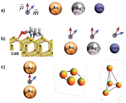
[image:2.595.310.550.52.247.2]with the electronic states of a nanocrystal, which leads to the chirality of electronic surface states of a nanocrystal; a nano-crystal acquires chiral atomistic defects ‘‘imprinted’’ by adsorbed molecules; a very small nano-crystal (cluster) has intrinsically a chiral atomic structure; etc. The mechanism (a) relies on a chiral atomistic structure of a nanocrystal or a cluster, like in the case of purely molecular chiral systems. The mechanism (a) has also close relevance with the effect of chiral footprints on a crystal surface being modified by a chiral adsorbate and, therefore, acquiring interesting chiral and optical properties.14,15 The mechanisms (b) and (c) have, however, a different character. The idea behind these mechanisms is to construct optically-active chiral nanostructures from well-defined, preformed chiral and non-chiral building blocks. This approach is also applicable towards the construction of efficient sensors using optically active nanostructures that may amplify weak optical chiral signals of molecules and bio-molecules. It is challenging to predict chiral atomic ‘‘constructions’’ of nanocrystal surfaces needed for the mechanism (a). On the other hand, the mecha-nisms (b) and (c) do not require new chiral atomistic structures, but they involve new arrangements of interacting chiral and non-chiral nanoscale blocks. The interaction or coupling between these blocks play a key role in the formation of new chiral properties and can be very strong involving dynamic Coulomb and electromagnetic fields.16,17 Of course, the chiral nanoscale assemblies needed for the mechanisms (b) and (c) may also be challenging from the point of view of realization. Section 1.1 will describe a few recent realizations for the mechanisms (b) and (c) when either the plasmon-plasmon Coulomb interaction becomes involved11,18,19 or dynamic chiral molecule-plasmon coupling represents a suitable mechanism for the observed CD signals.20,21 Fig. 1 shows a set of chiral and non-chiral building blocks as well as a few simple assemblies. A chiral chromophore molecule (dye molecule) is depicted as a point-like object with two dipoles,
~
m andm~, that are the optical electric and magnetic moments. Importantly, building blocks depicted in Fig. 1a have very different optical and electromagnetic properties as illustrated by Fig. 2. Molecular systems show mostly strong optical chirality in the spectral UV range. As an example, proteins and DNA have the CD bands in the range of 150–300 nm. A macroscopic ensemble of crystalline nanocrystals (metal and semiconductor) typically does not exhibit any CD and have absorption bands in the visible range. Importantly, metal nanocrystals are able to strongly enhance electromagnetic field in their vicinity (Fig. 2b), whereas molecules do not noticeably change external fields. Semiconductor quantum dots may modify external electromag-netic fields in their vicinity due to the dielectric effects (Fig. 2b). According to the general quantum theory of optical activity, a strength of CD signal of a molecule:1,2,22
CD0Im(m12$m21), (1)
wherem12andm21are quantum matrix elements of the electric
and magnetic dipole operators, respectively, and the indices 1 and 2 denote the ground and excited states of molecule, respec-tively. If a molecule has an orbital interaction with the surface of a nanocrystal via an overlap of electron wave function, the
Fig. 1 Chiral and non-chiral elements, and their complexes. a) Building and non-chiral building blocks: chiral molecule represented by optical electric and magnetic dipoles (~mandm~) and non-chiral nanocrystals of various materials. b) From left to right: Proposed model of binding of a chiral molecule (D-Pen) to a surface of CdS quantum dot;23 dipolar-interaction models of hybrid complexes composed of non-chiral nano-particles (semiconductor or metal) and a point-like chiral molecule. The left panel is reprinted with permission from Ref. 23. Copyright 2008, American Chemical Society. c) From left to right: A chiral dye molecule placed in a plasmonic hot spot between two non-chiral plasmonic nanocrystals and chiral assemblies from non-chiral blocks (spherical metal nanoparticles).
Fig. 2 Optical, chiral, and electrodynamic properties. a) Normalized extinctions of a molecule, Ag and Au nanoparticles, and CdTe quantum dot (2.7nm size).96A chiral molecule has an absorption resonance at 200nm. b) Electromagnetic properties of the nanocrystals. The field enhancement factorPzis calculated at the surface of nanocrystals for the geometry shown in the inset. c) Chiroptical properties of a typical dye molecule with an absorption line in the UV range. Circular dichroism (CD) and optical rotatory dispersion (ORD) come always together and are coupled by the Kramers-Kronig transform.
[image:2.595.322.533.384.625.2]resulting electronic structure and optical spectra should be calculated using atomistic approaches;7,23–27 ref. 4 and 7 may
serve as review papers to learn about the atomistic calculations. A molecule in this case can leave a chiral ‘‘footprint’’ on the surface states of a nanocrystal.4,14Another mechanism of inter-action is a dynamic Coulomb coupling. This coupling is espe-cially strong in the case of plasmonic nanocrystals. Plasmonic nanocrystals are able to strongly enhance both the electromag-netic field of incident wave and the dynamic Coulomb interac-tions between parts of assembly.28,29Then, the CD strength of
a chiral molecule should be rewritten as9,10
CDmoleculeIm[(P^$m12)$m21], (2)
where P^ is the plasmon enhancement matrix for the external electric field. In the case of a spherical nanocrystal, this enhancement matrix is diagonal. The magnitude of the z-element of this matrix at the surface of a nanoparticle is shown in Fig. 2b where the typical plasmonic enhancement peaks can be clearly identified. We should note that, in the case of spherical nano-particles, the maximum plasmonic enhancement factors are only
6 (Au) and 16 (Ag). However, for plasmonic hot spots in metal nanostructures and resonators, these factors can be much larger.30 One realization of a plasmonic resonator is a nano-particle dimer with a molecule placed in the hot spot between the nanoparticles (Fig. 1c, first image from the left). In the following sections, we will discuss this situation in more details. The CD signal CDmolecule (eqn (1)) can be strongly amplified by the
plasmon resonance, but it still appears at the frequency of molecular transition. Here it is important to note that, typically, strong CD transitions of chiral molecules and plasmonic bands of typical metals (Au and Ag) are often not in resonance. Strong molecular CD bands are typically in the UV range, whereas the plasmon resonances of Au and Ag nanocrystals are in the range of 400–800 nm. Therefore, it is not always possible to utilize the plasmon enhancement effect directly for amplification of molecular CD bands. Nevertheless, a molecular CD band and plasmons may strongly interact via the mechanism proposed recently.9,10This mechanism appears in a complex composed of
a chiral molecule and a metal nanocrystal. A plasmon interacts with a chiral moleculeviadynamic Coulomb fields and acquires a chiral character. Consequently, the CD spectrum of such complex acquires a plasmon peak. The plasmon CD strength of a complex composed of chiral molecule and metal nanocrystal includes parameters from both components:
CDplasmon,molecule-nanocrystal(l)Im[(F^plasmon$m12)$m21]$
Im[3metal], (3)
wherelis the photon wavelength,3metalis the dielectric function
of a metal nanocrystal and ^Fplasmon is a tensor that strongly
depends on the geometry and, of course, includes the strong plasmon-enhancement effects. The factor Im[3metal] in eqn (2)
tells us that the optical absorption occurs in the metal compo-nent. Simultaneously, the chirality at the plasmon resonance comes from the molecule since CDplasmon, molecule–nanocrystal
includes the molecular dipole matrix elements,m12andm21. We
can also see that, in general, the chiral plasmon response
CDplasmon,molecule–nanocrystalat the plasmon wavelength originates
from the optical rotatory dispersion of a molecule, ORD0
-(lplasmon), wherelplasmonis the plasmonic-peak spectral position.
We note that, in an isolated molecule, ORD0(u)Im(m12$m21)
(Fig. 2c). At the same time, the CD strength of a molecule can be very weak at the plasmon wavelength since a molecule can absorb at a very different wavelength. This situation is illustrated in Fig. 2. In addition, the plasmon CD decreases with the distance between a molecule and a nanocrystal for the obvious reason that the plasmonic CD originates from the Coulomb interaction between a molecular dipole and a metal nanocrystal. For a spherical nanoparticle, one can obtain an exact result:9,10
CDplasmon;moleculenanocrystal
a3 R3;
whereaandRare a nanoparticle radius and a center-to-center distance in the molecule-nanocrystal pair, respectively. The behavior R3 is typical for the dipole–dipole interaction and the factora3comes from the polarizability of a nanocrystal. The
resultCDplasmon,molecule–nanocrystalR3holds for a nanocrystal
of an arbitrary shape at long molecule-nanocrystal distances. If a nanocrystal has a complex shape or our hybrid system incor-porates a few nanocrystals, eqn (3) will include multipole Coulomb interactions between the plasmonic component and the dipole of a chiral molecule.
Interestingly, the plasmonic CD mechanism described by eqn (3) has its origin in the Fano interference effect31in the
exciton-plasmon system.32The CD signal comes from the interference of the external field and the field induced by the molecular dipole inside the metal nanocrystal.
The plasmonic CD mechanism described above is not the only one. Using non-chiral metal nanocrystals, one can construct a system with optical chirality by arranging nanoparticles in a chiral geometry. Two possible chiral arrangements, short helix and asymmetric pyramid, are shown in Fig. 1c. The optical chirality and CD at the plasmon wavelength appear in this case due to dipole–dipole plasmon–plasmon interactions in a chiral assembly.12,13 Mathematically, the CD signal should be
computed as extinction of an absorptive metal object:
CDplasmonplasmon;nanocrystalðuÞ hQþQiU;
Q¼ 1 2Re
ð
V
j /*
u;ðr
/ Þ$E/0
u;ðr
/Þ
dV; (4)
whereQare the extinction rates of plasmonic NPs for the two incident waves (), and~ju,*and~Eu,are the complex ampli-tudes of the induced electric current and the incident electric field, respectively. The averaging over the solid angle,h/iU, is performed since the complexes are randomly oriented in a solu-tion. Interestingly, the signal depends really strongly on the size and the inter-particle distance:12
CDplasmonplasmon;nanocrystalðuÞ
a12 d8;
whereaanddare the nanoparticle radius and the size of a chiral complex, respectively. The above equation was obtained for the dipole–dipole interaction in a chiral complex made from iden-tical NPs. This CD mechanism somewhat resembles the CD mechanisms in molecular systems that come from interaction of non-chiral chromophores arranged in a chiral geometry.1,33This
situation appears in helical molecules in the spectral UV range (proteins)1,2and it also may occur in assemblies of dye molecules
and DNA in the visible range.34
This review paper is organized into two sections. The first section describes chiral nanostructures based on metals (Au and Ag), whereas the second section deals with chiral semiconductor quantum dots. Along with a description of synthesis and chi-roptical properties, the discussions in this review will include interpretations and some elements of theory.
1.
Chiral metal nanoparticles and their assemblies
1.1 Chiral gold nanoparticles
Due to their biocompatibility and relatively easy functionaliza-tion, gold nanoparticles (NPs) are very attractive for biomedical applications including nucleic acid analysis and gene regula-tion.35Therefore their interactions with DNA have been
inves-tigated depending on the functional groups on their surface. It was thus shown that the binding of DNA to functionalized gold nanoparticles induced a conformational change in the double stranded helix which became denatured. This was translated in the CD spectrum by a shift and decrease in the peak of duplexed DNA.36In a different experiment,37AuNPs were employed to
create DNA-templated AuNP chains and, again, the UV-CD spectroscopy was successfully used to record conformational changes of the DNA template.
The synthesis of chiral gold NPs normally involves the use of chiral thiolated stabilizers such as L-glutathione, penicillamine or N-isobutyrylcysteine to name a few.38However, DNA-gold
nanoparticle systems have not been very much investigated from that point of view. Instead they have been used to form assem-blies which could be made chiral. Controlled, ordered assemassem-blies of gold NPs may find applications in the construction of elec-tronic and optical devices on small scales. The most common strategy for DNA directed assembly is the modification of different batches of nanoparticles with complementary strands of single-stranded (ss)-DNA and subsequent hybridisation.39–41 Other methods include the use of a linker sequence to hybridize
the two ss-DNA strands immobilized on the nanoparticles42,43 but also formation of double-stranded (ds)-DNA prior to binding to nanoparticles on both ends. The latter strategy was proved very efficient for creating dimers.40However, it does not
suit the formation of higher geometry assemblies. All of these nanostructures rely on the binding of thiol-modified DNA sequences to the gold. It was shown that the chain length and sequence as well as the choice of thiol-spacer strongly influence the resulting assemblies.43Chiral assemblies of DNA-modified
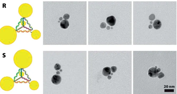
gold nanoparticles was thus made possible by controlling the binding of four different-sized building blocks (Fig. 3).41
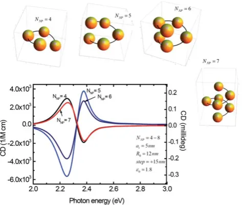
Even though the study41did not report any CD spectra, it is very interesting to model possible chiral optical CD signals for such or similar metal NP assemblies, to identify NP geometries with the strongest CD signals. The related theoretical study was recently reported12,13 and gave very interesting results (Fig. 4). First, since the CD effect here comes from the dynamic Coulomb interaction between non-chiral NPs arranged in a chiral geom-etry, the shape and strength of calculated CD signals are really sensitive to the composition and geometry of NP complex. Removing or shifting one NP in a chiral complex of four nano-crystals can change the overall CD signal or sometimes can cause it to vanish. In the case of a four-NP complex, the reason of this sensitivity is purely geometrical. If we remove just one NP from a complex of four, the remaining system becomes non-chiral since it acquires a symmetry mirror plan. Another example is a chiral pyramid made of four NPs of the same size (Fig. 4, upper part, first two complexes). In this case, if the NP (a) in Fig. 4 (upper part) is moved to the right, the resulting pyramid will become non-chiral because of the symmetry plane coming through the vertical pair of NPs (b and c) and the center on the a–d edge. Chiroptical properties of plasmonic pyramids and tetrapods found by Fan et al.12 can be briefly formulated as follows: (1) Especially strong chirality appears if a frame is chiral; (2) Chiral assemblies with non-chiral frames have typically weaker CD; in this case, it is assumed that at least two NPs out of four should have different sizes; and (3) A CD signal from a chiral complex with an ideal tetrahedral frame seems to vanish in the dipole model; this case assumes that all four NPs have
Fig. 3 Chiral assemblies of gold nanoparticles using DNA scaffolds.41Reprinted with permission from Ref. 41. Copyright 2009, American Chemical Society.
[image:4.595.132.469.520.698.2]different sizes because, otherwise, the complex is not chiral. After evaluating several geometries, the authors12,13 came to the conclusion that the helical geometry of plasmonic NPs is really suitable for the creation of plasmonic CD (Fig. 5). Interestingly, it was found that the CD signals within the dipolar theory of plasmon-plasmon interaction have typically a peak-dip shape (bisignate shape). In a few-NP helices with a relatively small vertical separation between NPs (as shown in Fig. 5), the plas-mon CD band may became inverted as one NP is added. However, if we average over helices with different NP numbers (NNP), the net averaged CD will still remain strong. Moreover, it
was demonstrated theoretically that helixes with a more ‘‘stretched’’ geometry have very stable CD spectra without ‘‘inversion’’ when the NP number increases.13 The overall
conclusions of ref. 12,13 are that: (a) if a system has some degree of helical correlations of NP positions, one can expect a substantial plasmonic CD signal, (b) defects will, of course, somehow reduce the CD strength, and (c) it is possible to find geometries with the plasmonic CD bands that are especially stable against possible defects of structure (missed NPs or a variation of the NP number in a helix). Interestingly, plasmonic peak-dip (bisignate) structures in the CD spectra have been recorded in several experiments.44,18,45,46 The assemblies18,45
involved Ag NPs and will be described in Section 1.2 (Fig. 9 and 11 and related text). In the study44peptide-templated chiral gold nanoparticle assemblies were obtained by thein situgrowth of gold on D- or L-diphenylalanine nanotubes. Diphenylalanine forms chiral nanotubes with either right- or left-handed config-urations from D- or L-isomers, produces tubes with homoge-neous lengths, and represents a scaffold for nanoparticle growth. The tubes were subsequently coated with preformed 4.5 nm ethylene glycol protected gold NPs and then used to seed the selective growth of gold NP bunches along the nanotube surface. After growth, the attached gold bunches showed a bisignate CD signal at the gold plasmon frequency and a symmetrical mirror image of peaks with complementary positive/negative and negative/positive Cotton effects for the D- and L-isomers respectively. For these nanotube-grown gold assemblies, it was suggested that the induction of chirality and creation of CD activity originates from plasmonic resonances of asymmetrically organized gold NPs on the nanotube. This plasmonic CD signal may be either due to the intrinsic chiral properties (chiral shape or chiral surface electronic states) of NPs or to the inter-NP coupling in a chiral NP array. So far, a theory has only been developed for the second case12and it, indeed, predicts bisignate
CD signals. In another assembly approach11DNA has been used to arrange gold nanoparticles in spatially defined 3D geometries using a PCR based method. To obtain assemblies, DNA func-tionalized gold NPs from a diverse pool of shapes and sizes were assembled into multi-NP architectures by varying the density of DNA primers on the Au NP surface and the number of PCR cycles. Under these conditions, NP dimers, trimers, and tetra-mers were formed. Notably, the resulting structures mimicked the chirality of simple few-atomic molecules. Optically, these arrangements produced intense CD signals of complex shapes at
650 nm probably as a result of the collective plasmon coupling. Overall, it may be challenging to identify an exact mechanism of Fig. 4 (Upper part) Models of chiral NP pyramids shown to scale. The
first two models have an asymmetric frame and NPs of the same size. The third model is with a symmetric frame, but with different NPs. (Lower part) Calculated CD spectra of pyramidal complexes with asymmetric frames. (Insert) Calculated CD for the complex with a symmetric frame. The positions of NPs and more description can be found in Fanet al., 2010.12 Reprinted with permission from Ref. 12. Copyright 2010, American Chemical Society.
Fig. 5 Calculated CD spectra of helix complexes (NNP¼4, 5, 6, and 7) with the parameters shown inside the graph;R0is the radius of helix,step is the period (pitch) of helical structure, andaNPis the NP radius. Inserts: models of the complexes shown to scale. Reprinted with permission from Ref. 12. Copyright 2010, American Chemical Society.
[image:5.595.49.281.50.351.2] [image:5.595.312.549.54.255.2]plasmonic chirality in these assemblies since they are non-uniform in composition and the CD spectra in the plasmonic wavelength region have complex shapes.
Very recently, two studies47,48reported Au-nanorod assemblies
demonstrating plasmonic CD responses with the characteristic bisignate shapes. According to the interpretation,47,48these CD responses come from the plasmon-plasmon interaction between nanorods. The first report47 concerns a nanorod structure
assembled with twisted fibers, whereas the second paper48utilizes
soft bio-molecules for a templated assembly. In contrast to spherical-NP assemblies, nanorod complexes have an additional type of disorder - an orientational disorder. In experimental realizations, the control of orientations of nanorods in an assembly can be an additional challenge. The second paper48
demonstrated an interesting effect of flipping of the plasmonic CD pattern using a chemical method. According to the inter-pretation of Wang and co-workers,48the controlling molecules added to the solution create changes in the geometry of the assembly and, in particular, these molecules can cause a change in the pitch of the helical nanorod assembly. This variation of a pitch may result in a flipping of the plasmonic CD spectrum. This flipping effect is supported qualitatively by the theory.13In the theoretical calculations for the helical plasmonic complexes, one can see the effect of inversion of a CD spectrum when a helical complex becomes stretched or compressed.13 The
observed sensitivity of the plasmonic CD spectrum to the geometry of a complex assembled with the help of a biomolecular template suggests interesting possibilities in bio-sensing applications.
On the other hand, an optical activity may, in principle, arise locally from random aggregation of nanoparticles, even without any chiral species in the vicinity, due to the fact that they gather with no centre or plane of symmetry and are therefore likely to exhibit local handedness. Large local optical activity was found in particular in fractal aggregates of plasmonic nanoparticles, while no macroscopic circular dichroism was observed. This phenomenon was explained by the formation of hot spots where the exciting electromagnetic field concentrates and may enhance optical activity.49Another possibility to create plasmonic CD would be the use of random aggregates assembled using chiral molecules. In such aggregates, plasmonic fields may be strongly enhanced in hot spots and, therefore, the interaction between plasmons and chiral molecules can be strongly amplified.9,10This type of optical activity, in principle, may appear in a large collection of random aggregates assembled with molecules of the same kind and chirality. Geometries of random aggregates would be overall non-chiral (i. e.with random chirality), but non-zero optical chirality may come from the uniform chirality of mole-cules. In recent experiments, phosphorothioate-modified
oligo-nucleotides were immobilized on 10 nm-diameter gold
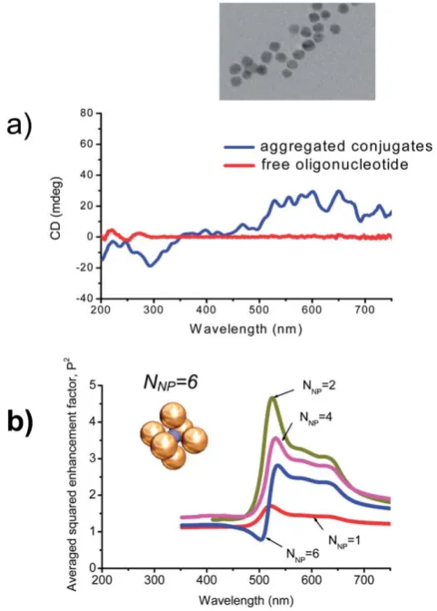
nanoparticles which then exhibited a plasmon-induced CD in the 500–700 nm region21 (Fig. 6). However, this CD was only
observed when the conjugated particles were partially aggre-gated. The reversibility of the phenomenon upon de-aggregation and aggregation suggested that the density of plasmonic particles around the chiral species and possibly the distance between them were key elements in the generation of plasmon-induced CD. Overall this observation of plasmon-induced CD in random aggregates is consistent with the plasmonic dipolar mechanism
described by eqn (3). Importantly, this mechanism creates CD lines in a wavelength region where an attached chiral molecule has not its own absorption. It is expected (eqn (3)) that the appearance of plasmonic lines in the CD spectrum should correlate with the plasmonic enhancement of field inside the system. And, indeed, it is interesting to see such correlation in Fig. 6a and 6b. The calculated plasmon enhancement spectrum in Au-NP assemblies has a characteristic band starting at 500nm and ending at 700nm (Fig. 6b). This is what we also see in the experiment (Fig. 6a). We should note that the calculated Au complex shown in Fig. 6b has a relatively large inter-particle distance and, therefore, the plasmonic enhancement factor is just moderate. For smaller inter-particle separations, one can obtain theoretically very large enhancement factors, for example, an Au-NP dimer with 2nm gap showsPz300.30
It appears that special conditions have to be simultaneously fulfilled for plasmon-induced CD to occur: the plasmonic parti-cles must be densely packed and the chiral species must be close enough to the plasmonic particles. The conditions were achieved Fig. 6 a) CD spectra measured by Gerard and co-workers for oligo-nucleotides alone and for aggregates of 10nm Au NPs conjugated with oligonucleotides. Inset: TEM image of oligonucleotide-conjugated gold NPs.21 Taken from Ref. 21; adapted with permission of The Royal Society of Chemistry. b) Calculated averaged plasmonic enhancement factors (P2) for the plasmonic hot spot in the center of an assembly ofN
Au nanoparticles. Inset: Geometry of one particular complex withNNP¼6; the plasmonic hot spot is located in the center of the system indicated as a blue sphere. Adopted with permission from Ref. 97. Copyright 2006, American Chemical Society.
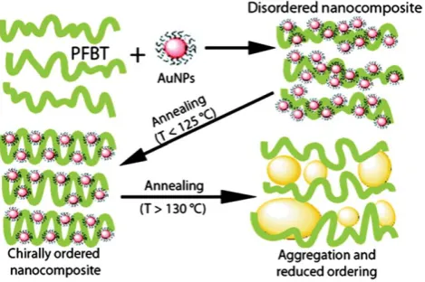
[image:6.595.308.549.53.390.2]by Oh and co-workers19who assembled gold nanoparticles on
a chiral polymer, poly(fluorene-alt-benzothiadiazole) (PFTB), to produce ordered nanocomposites with strong CD at the plasmon resonance wavelength especially after annealing of the produced polymer film (Fig. 7). The observed CD signals were interpreted in terms of the two plasmonic mechanisms:9,10,12(i) plasmonic
coupling between helically arranged gold NPs because of this supramolecular ordering and (ii) the dipole–dipole exciton-plasmon coupling between the polymer and exciton-plasmons resulting in transfer of chirality from the chiral molecules to the Au plasmons. From a close look at the observed CD spectra, it may be observed that the CD spectrum of the chiral nanocomposites19
includes strongly enhanced natural molecular transitions, which are expected within the mechanism (ii). The related simple equation for this mechanism is eqn (2). Thus it seems that the condensed phase would be auspicious to the generation of CD in the plasmonic region on the condition that the inter-particle distances and the particle arrangement can be controlled somehow. This general observation is consistent with the recent theories9,10,12of plasmonic CD appearing in NP assemblies with chiral geometry.
As described in the examples above, a collective response of metal nanoparticles can be essential to enhance molecular CD or to create new plasmonic lines in a CD spectrum. As a result, massive metal nanostructures (plasmonic meta-materials) were employed to increase the sensitivity of CD for the detection of chiral biomolecules50using concepts somewhat related to those
presented above. In an elegant example, Hendry, Kadodwala, and co-authors constructed a planar chiral metamaterial based on an array of right- and left-handed gold gammadions on glass to create chiral plasmonic hotspots for the detection of chiral biomolecules. Analysis of six common proteins (hemoglobin, bovine serum albumin,b-lactogobulin, myoglobin, concanavalin A, outer membrane protein) with their right-handed and left-handed chiral arrays has been performed and the proposed plasmonic meta-material method has shown its potential for sensing.
Another important parameter to take into account is the nature of the chiral molecule itself. While DNA is a long mole-cule subject to many conformational changes, small chiral amino
acids produce very different effects. For instance D- and L-penicillamine were successfully used to stabilize gold clusters produced in their presence which exhibited new spectral CD structures, especially well seen in the anisotropy-factor spec-trum.51 However the immobilization of the same moieties on citrate-stabilized gold nanoparticles through ligand exchange did not give rise to any CD;52the same results were obtained also recently by another research group.21Two main atomistic models
have been argued as for the origin of chirality in these systems. The first one involves the formation of a chiral gold core due to the influence of the chiral ligand; the second model relies on Metal-Based Electronic Transitions (MBET) being linked to a perturbation of the symmetrical core by a chiral field. Chiral thiol-stabilized gold nanoparticles were examined when exposed to the free thiol of opposite configuration, a racemic mixture of thiols and an achiral thiol.38 Ligand exchange was shown to occur and to give rise to an inversion of chirality. The shape of the spectrum was unchanged and the intensity of CD was not sensitive to excess ligand in the solution. This was an indication that the CD could not be solely attributed to a chiral arrange-ment of thiols on an achiral nanocluster. On the other hand, the inversion of chirality with ligand exchange proved that the CD did not come from a chiral gold core. It was postulated from these results that chirality of thiol-stabilized nanoparticles was due to a local distortion of the gold crystal on the surface of the particles through the adsorption of the chiral ligands. That chiral structure was probably not stable enough to withstand ligand exchange.38
The large variety of available chiral molecules brings many interesting possibilities. In one example,53Au NPs with a well
expressed plasmon resonance were conjugated with chiral calix-arene enantiomers. The resulting CD spectrum of the conjugate demonstrated a weak, but well-defined plasmon peak at520 nm. By analyzing their data and structures, the authors concluded that their observation is consistent with the chiral asymmetry effect induced by the chiral adsorbate that influences the electronic structure of the metal nanoparticle core.53It should
be added that the observation is also consistent with the dipolar mechanism of interaction between chiral molecules and plasmons.9,10
Peptides (short chains of amino acids-short proteins) represent another source of biomolecules that can be used to create interesting nanoparticle chirality. Peptides can be engineered to exhibit material specific binding by using combinatorial screening techniques. They can exhibit various secondary struc-tures (a-helix, random coil, b-sheet), can be conjugated with dyes, and can be multi-functional. A complex composed of a chiral peptide, a non-chiral dye molecule, and a silver NP exhibited strong plasmon enhancement of the natural CD lines54 that will be discussed in more details in the next section. Recently, Pradeepet al.showed that the CD response of gluta-thione coated gold can be manipulated by the etching and cavi-tation of the parent particles into quantum clusters of Au15using
excess glutathione and cyclodextrin molecules.55After etching, the quantum particles displayed strong luminescence and intense CD peaks at330–380 and 400–455 nm from the gold cluster core. Other peptide-nanoparticle systems with artificially created CD included gold nanoparticles functionalized with a well established gold-binding or coiled-coil peptide,56,57and peptide Fig. 7 Formation of ordered PFTB and gold nanocomposites with
enhanced chirality. Reprinted with permission from Ref. 19. Copyright 2010, American Chemical Society.
[image:7.595.50.285.54.210.2]templated silver-silica core shell hybrid nanoparticles.58For the
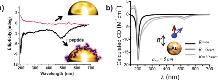
gold-binding and coiled-coil peptides, Slociket al.56observed the
creation of moderately strong visible CD signals at the plasmon frequency of gold (Fig. 8). This observation was attributed to the mechanism due to the interaction of dipoles from the chiral peptides with the plasmons of the gold nanoparticle (eqn (3)). It is interesting to note that while these peptides had differing secondary structures (unstructuredvs.a-helical), they produced CD signals with similar magnitude and ellipticity. By compar-ison, the strength of a dipole in ana-helical peptide is larger than in an unstructured peptide and is expected to induce a stronger CD response from gold, however, the unstructured peptide binds in a multi-dentate fashion and interacts with more of the gold surface than the a-helical E5 coil peptide which binds through a single cysteine residue extending the dipole farther away from the gold surface.56 This could reduce the transfer of chirality
from the helical E5 coil peptide to the Au NPs.
The influence of Au NP’s core diameter was investigated in the work of Schaaff and Whetten.59 Small glutathione-stabilized nanoparticles (less than 2 nm) were synthesized, which can also be viewed as large clusters (20–40 atoms). Their UV-visible absorption spectra were very different from the usual plasmon peak at 520 nm that is typically observed for Au NPs with diameters larger than 5nm. Due to quantization of the electronic transitions, they demonstrated a step-like structure ranging from red to near-IR. It also differs from smaller clusters which typi-cally exhibit a strong blue absorption band. This peculiar elec-tronic structure was also reflected in their CD spectra where several very intense bands and frequent changes of sign could be observed. These bands were further evidence for a series of distinct electronic transitions, but also strongly suggested that the core AuNPs were intrinsically chiral. Similarly to previously reported chiral fullerenes60 and helicenes,61 these large gold
clusters are thought to assemble in a helical or generally low symmetry way.59
1.2 Chiral silver nanoparticles
Silver ions have been known to complex with nucleic acids via
interactions with the heterocyclic bases and to consequently alter their optical properties. This affinity has been used to grow silver
nanoparticles assemblies on DNA templates. Reducing silver ions previously complexed to 700 base pair poly(dG)-poly(dC) lead to the formation of linear chains of silver nanoparticles.45 The initial complexation induced an inversion in the CD band of DNA at 260 nm, while the formation of nanoparticles lead to the appearance of a new band at 425 nm which was the plasmon resonance frequency of the silver particles (Fig. 9). On the other hand, pre-made nanoparticles subsequently mixed with DNA did not give rise to that new CD. It was thus concluded that DNA directed the asymmetric growth of nanoparticles.
Regarding Ag-based hybrids, it was postulated that the interactions of Ag+ with DNA induces some conformational
changes and that the modification of the bases arrangement relatively to the helical axis is responsible for the changes in CD. Silver nanoparticles in turn induce different alterations of the DNA conformation and consequently of the CD spectrum.62
Very recently, the modification of citrate-stabilized silver nanoparticles with a range of small thiolated chiral molecules through ligand exchange showed that the availability of a protonated amine group may give rise to a CD signal in the plasmon region (350–550 nm), the sign of which did not depend on the handedness of the ligand.63Rezankaet al.63attributed this
CD generation to the mechanism due to the dipole-plasmon interaction.9,10 Cysteine, penicillamine and glutathione which
interact with silver nanoparticles through their thiol group produced a new CD signal in the 240–300 nm range (around the optical activity region of initial biomolecules). In the case of cysteine, the generation of that new CD signal was attributed to hydrogen bonding between amine and carboxylic acid moieties of neighbouring cysteine-capped silver nanoparticles.52 Interest-ingly, the new CD was not generated when the same molecules were bound to gold nanoparticles.
Lieberman et al.54 conjugated Ag NPs and a peptide-dye
complex (Fig. 10). The fluorescent dye (bromobimane) was nonchiral. In this case, the optical transition in a peptide-dye complex (400nm) and plasmon Ag NPs were in resonance (400nm). As a result, the CD signal of a peptide-dye complex was amplified by two orders of magnitude.54The authors attributed
this CD amplification to the plasmon enhancement of absorption in the system.54Since the CD spectrum of the complex included
structures at the natural wavelength of the dye, we can estimate Fig. 8 a) Plasmon enhanced CD spectrum of Au nanoparticles functionalized by a peptide-dye conjugate and Au nanoparticles coated by a gold-binding peptide. b) The calculated CD spectra for a dipole of a generic chiral molecule mimicking peptide chromophores (black curve forR¼N) and for a dipole-nanoparticle complex with two separations (R¼5.3 and 6 nm); the absorption wavelength of the dipoleldipole¼200nm. Inset shows the model used. Reprinted with permission from Ref. 56. Copyright 2011, American Chemical Society.
[image:8.595.117.485.55.191.2]theoretically the plasmon enhancement effect using eqn (2). The plasmon enhancement of natural molecular CD line is propor-tional to the plasmonic factorP. At the surface of a spherical Ag NP, the plasmon enhancement is moderate:P16(Fig. 2b). This is not enough to explain the observed 100-fold enhancement.54
Au-NPs were however likely to be partially aggregated and besides Ag NPs involved in this study were relatively large (2– 50nm). Therefore, hot plasmonic spots could appear in this system. For example, a 20nm-Ag NP dimer with a gap of 1 nm creates a plasmonic hot spot in the center withP700.30This is even larger than the observed enhancement. In the real system, not all chromophores can be located in hot spots and the resulting CD increase will be smaller than the maximum enhancement factor. From the above theoretical number for the factorPin the hot spots, we see that the plasmon-enhancement mechanism is a resonable explanation for the important obser-vation of Liebermanet al.54
Similarly to the case of Au NPs, peptide molecules can be used for conjugation with silver NPs. Taubert et al.58used peptide molecules to produce chiral silver nanoparticles coated with a thin optically transparent silica shell. These core-shell particles displayed a positive plasmon-induced CD peak for silver which was red-shifted by 37 nm upon addition of the silica coating. The origin of CD activity is believed to be the peptide altered crys-tallographic structure of silver and possibly the disordered crystal interface determined by X-ray diffraction. This suggested mechanism differs from the dipole-plasmon interaction mecha-nism which was assumed for the plasmonic CD signals of peptide functionalized chiral gold particles56as it was described above, in
Section 1.1. We note that, in principle, the dipole-plasmon
interaction mechanism is also applicable to the interesting structures realized by Taubert and co-workers.58Clearly, more
studies and more specially-designed structures are needed to distinguish and to uniquely identify the involved CD mechanisms and it can be that a few mechanisms can act simultaneously.
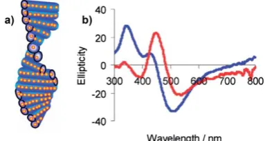
Another recent and interesting experimental realization of a chiral system with a strong plasmon-related optical activity was reported by Qi and colleagues (Fig. 11).18The authors employed
nematic porous silica films with embedded silver NPs and observed characteristic plasmonic structures in the visible spec-tral range (Fig. 11).18 The CD spectra in this study exhibited positive and negative bands that are quite typical of the CD mechanism based on the plasmon-plasmon Coulomb interaction between metal NPs.12One can see similar bisignate structures in
calculated CD spectra of NP complexes of various geometries, including the related helical geometry (Fig. 4 and 5).
2.
Chiral semiconductor quantum dots (QDs)
[image:9.595.95.500.54.205.2]Over the last decade much attention has been directed towards II–VI semiconductor nanoparticles such as CdS, CdSe and CdTe quantum dots (QDs).64–74 It is the ability to finely tune their optical properties through chemical control of their size and shape (i.e. their degree of quantum confinement) that makes quantum dots particularly interesting. This level of optical control combined with QDs resistance to photobleaching and Fig. 9 The plasmonic CD band of Ag NPs assembled on DNA (left) and the geometry of the system including a TEM image of the Ag NP chain (right). Reprinted with permission from Ref. 45. Copyright 2006, American Chemical Society.
Fig. 10 CD from the peptide-dye-Ag NP complex; inset shows a model of the system. Reprinted with permission from Ref. 54. Copyright 2008, Wiley.
Fig. 11 a) A model of nematic porous silica films with embedded interacting Ag NPs. b) CD spectra taken from this system before (blue) and after (red) soaking with water. Reprinted with permission from Ref. 18. Copyright 2011, American Chemical Society.
[image:9.595.110.225.255.324.2] [image:9.595.332.524.573.675.2]their high level of solubility in practically any solvent (depending on the stabilizer used) makes these nanomaterials potentially suited for roles as diverse as light emitting diodes,75biological
sensors76and photovoltaic devices.77–79Thiol group containing
amino acids have proved to be excellent stabilizers, with L-cysteine becoming one of the most popular surface capping molecules for CdX (X¼S, Se, Te) nanoparticles.67,80–86Recently the use of stereospecific chiral stabilizing molecules opened another avenue of interest in the area of quantum dot research, as chirality is a key factor in biological and biochemical inter-actions. However this is a very new area. There are currently only a limited number of relatively recent reports dealing with chiral
light emitting semiconducting nanocrystals (quantum
dots).23,27,87–89
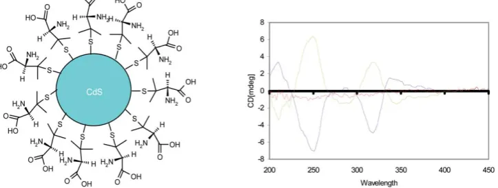
Initially chiral CdS QDs were prepared using microwave induced heating with the racemic (Rac),D- andL-enantiomeric forms of penicillamine (Pen) as the stabilizers.87 Circular dichroism (CD) studies of these QDs have shown that D- and L-penicillamine stabilized particles produced mirror image CD spectra (Fig. 12) while the particles prepared with a Rac mixture showed only a weak signal. Because the particles are optically active from 200–360 nm, the chirality cannot be simply attributed to the penicillamine ligand and therefore the QDs themselves can be considered chiral. It was also demon-strated that all three types of CdS particles (D-, L-, and Rac
penicillamine) show very broad emission bands between 370 and 710 nm with the maximum wavelength in the range 485– 505 nm due to defects or trap states on the surfaces of the crystals. DFT calculations of electronic states have demon-strated that the longer-wavelength circular dichroism is asso-ciated with near-surface Cd atoms that are enantiomerically distorted by the penicillamine ligands.23Models of the CdS QD surface show that the penicillamine ligand bondsviaN and S to one surface-Cd, and introduces chiralityviaadditional bonding of carboxylate to a neighboring Cd. The interaction between ligand and cluster is strong, as is the interaction between ligands on the surface, compared to the weaker CdS surface structure. The ligands thus pack into helical bands on the surface and strongly distort the outermost Cd atoms of the QD, transmitting an enantiomeric structure to the surface layers. However, there is little distortion of the CdS geometry in the QD core, which remains achiral.
More recently aqueous chiral CdSe quantum dots have also been synthesized using microwave heating.90These nanoparticles
also showed a very broad distribution of photoluminescence which originates from emissive defect states. According to time resolved photoluminescence spectroscopy studies, there is a range of defect states associated with each individual quantum dot as well as a shift of the emission band to longer wavelengths at longer times after excitation which suggests the existence of traps of varying depth.
The concept of chiral surface defects of QDs (distorted QD shell) was also confirmed by experiments with CdTe nanocrystals bearing chiral D- and L-cysteinemethylester hydrochloride ligands.88 Interestingly, the chirality of the QD surface was
maintained even after ligand exchange with an achiral thiol (Fig. 13) and transfer of CdTe QDs into a different (organic) phase. In this case chiral QDs have demonstrated an extraordi-nary chiral memory effect (Fig. 13).
It has also been demonstrated that the chirality of cysteine stabilizers has an effect on both the growth kinetics and the optical properties of CdTe nanocrystals.27,85This work suggested
[image:10.595.326.534.405.487.2]that the topological origin of chiral sites in nanocrystals is similar to that in organic compounds. Quantum mechanical calculations have shown that the thermodynamically preferred configuration of CdTe nanocrystals isStype when the stabilizer isD-cysteine andRtype whenL-cysteine is used as a stabilizer (Fig. 14). These calculations correlated well with the experimental kinetics of particle growth.27
Fig. 12 Left panel: Schematic of a chiral penicillamine capped CdS nanoparticle. Right panel: CD spectra ofL-penicillamine (green),D-penicillamine
[image:10.595.119.481.562.699.2](blue) and racemic (red) CdS nanoparticles.87Taken from Ref. 87. reproduced by permission of The Royal Society of Chemistry.
Fig. 13 Chiral memory of thiol-capped CdTe nanocrystals.88 QDs stabilized with chiral ligands retained their optical activity even after exchange with an achiral thiol. Reprinted with permission from Ref. 88. Copyright 2009, American Chemical Society.
In addition to QDs more complex chiral quantum structures have been reported. Unusual chiral CdS nano-tetrapods have been produced by heating of a basic aqueous solution of CdCl2, thioacetamide and racemic,D- orL-
enan-tiomeric forms of penicillamine (Pen) under reflux.91 These
materials have also shown a very broad emission band between 400 and 700 nm, which is indicative of defect emission. CD spectra of the D- and L- Pen stabilized samples showed clear CD responses within the band-edge region of the spectrum from 300– 400 nm, while the Rac-Pen samples as expected show no CD activity at all. It was found that further heating of the tetrapodal structures leads to the formation of chiral assemblies and their precipitation from solution. Preliminary biological testing showed that these materials demonstrate a very low cytotoxicity, which could be potentially useful forin vitrocellular imaging and biological sensing.
Self-assembly of CdS nanocrystals on chiral nanofibers have been recently reported.92The synthesis was achieved by growth
of CdS on the surface of synthetic self-assembled helical or nonhelical nanofibers after the immobilization of a peptide capping agent. It was found that there are differences in shape, size, and photoluminescence properties of the CdS nanocrystals depending on the chiral nature of the nanofibers on which they were grown.
Finally very interesting chiral CdS QDs have been prepared in ferritin protein nanocage.93These QDs have showed left-handed circularly polarized luminescence from both direct transition and surface-trapping sites. The authors have also demonstrated that the chiral luminescence can be modulated by laser photoetching. It was found that after photoetching the luminescent bands from surface trapping sites blue-shifted with a decrease in QD size, while bands from the direct transition band disappeared. Thus, chiral QDs demonstrate unique photophysical properties. It is expected that chiral QDs and their assemblies will find a range of potential applications including chiroptical memory and circular polarized light emitting devices, and assays for biological and biochemical analysis. The use of chiral QDs for recognition and analysis of chiral mixtures of enantiomers,89amino94and nucleic
acids,83 and for in vitro cellular testing95 have already been
demonstrated.
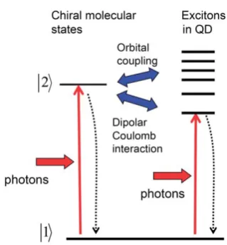
From a theoretical point of view, the induced optical chirality in semiconductor QDs reviewed in Sec. 2 can be explained by an orbital coupling or by the Coulomb interaction between a QD and a chiral molecule (Fig. 15). The first CD mechanism is microscopic and can only be treated using atomistic calcula-tions.23,27 In these calculations the electronic states of a QD
become hybridized with the orbital wave functions of a chiral molecule. In this way, i.e. via the orbital hybridization, the molecular chirality can be transferred to the excitons in a semi-conductor component. The second mechanism is similar to the plasmonic Coulomb-induced CD considered in Introduction.9,10
The theory of the Coulomb-induced CD developed for plasmons in metal nanocrystals can be easily extended to the case of excitons in semiconductor QDs.9,10 In a semiconductor QD, excitons become coupled with a molecular transition via the dipolar Coulomb interaction. The corresponding dipolar contribution to the CD spectrum at the excitonic wavelengths can be written as:9,10
CD exciton;moleculesemiconductor QDðuÞ
Im½ð^Fexciton$m12Þ$m21
R3
uu0 ðuu0Þ2þG2$Im
aQDðuÞ
; (5)
whereuandu0are the frequencies of the incident photon and the molecular transition, respectively;F^excitonis a dipole orientation
matrix. Importantly,aQD(u) is the polarizability of a QD which
contains the inter-band exciton resonances. The quantity Im [aQD(u)] is directly proportional to the QD absorption cross
section, sQD. Therefore, CDexciton, molecule–semiconductor QD(u) sQD(u). In other words, as expected, the dipolar CD spectrum contains the excitonic peaks observed in the absorption of an isolated QD. We also note that eqn (3) and 5 (which describe plasmons and excitons, respectively) have a somewhat similar structure. In addition, a simple theory predicts another dipolar mechanism of interaction between a chiral molecule and a non-chiral QD.9This mechanism arises from the modification of the
external electric field due to the high dielectric constant of a semiconductor. Such dielectric effect is expected to modify the intrinsic CD properties of a molecule due to the field enhance-ment factor,P^, in eqn (2).9
Conclusions and perspectives
The field of chiral nanoscale structures incorporating both nanocrystals and molecules is really exploding. There are several
[image:11.595.348.508.47.220.2]motivations for pursuing the development of chiral
Fig. 14 Quantum dot models of two different chiral arrangements of cysteine and CdTe. Reprinted with permission from Ref. 27. Copyright 2010, American Chemical Society.
Fig. 15 Quantum transitions in the chiral molecule-QD system. The solid vertical arrows represent light induced transitions, and the hori-zontal blue arrows depict the orbital and Coulomb couplings. The dotted vertical arrows show relaxation processes.
[image:11.595.48.286.56.146.2]nanostructures. Construct nanoscale systems with optical chirality in the visible range is very attractive since the majority of natural molecules exhibit a strong CD in the UV and a very weak CD in the visible range. Strong optical activity in the visible can be used to construct new media for optical devices. A large number of modern drugs are chiral and it would be very bene-ficial to have additional optical means - using the visible light - to identify their chiral states. Another motivation is the ability to sense chiral secondary structure of biomolecules (proteins, DNA,
etc) with light in the visible range. In that respect, plasmonic nanoscale assemblies look especially attractive because of the following opportunities: (i) Molecule-plasmon interaction can be made strong and local, applied only to the selected components of the system being sensed; this can be realized by attaching metal nanocrystals to selected parts of a complex bio-molecular system. (ii) Plasmon resonances can strongly enhance weak CD signals of molecules; (iii) Using plasmon resonances, one can bring the molecular CD responses to the visible range; this is especially attractive since all parts of a bio-system have typically very strong absorption and CD signals in the UV range.
The approaches to construct chiral nano-materials described in recent literature may be roughly divided into two groups. The first group is based on an assembly at the atomic level. This may involve metal/semiconductor nano-clusters with an intrinsic chiral structure (intrinsic chirality) or a surface chiral molecular adsorbate that induces chirality on a crystalline nanoparticle. Since nano-clusters, and especially nanoparticles, have a large number of atoms, it is challenging to control and predict their atomistic structure. This brings us to the second group of approaches. It concerns constructions of chiral nano-materials from well-defined building blocks using dipolar and electro-magnetic interactions. One advantage of this strategy is that it involves the controlled assembly of preformed building blocks and does not rely on the atomistic structure that may not be fully controlled. Overall we believe that new chiral nano-materials will find a range of potential applications and open up new horizons for unique optical devices, new approaches in asymmetric catalysis and chiral sensing.
Acknowledgements
This work was supported by NSF (A.O.G., Z. F.; project: CBET-0933415), Air Force Research Laboratories, Dayton, Ohio (A.O. G., J. M. S, R.R.N.), by Volkswagen Foundation (A.O.G.), and by Science Foundation of Ireland and Higher Education Authority (Y. K.G. and V. A. G.).
References
1 G. D. Fasman,Circular dichroism and the conformational analysis of biomolecules, Plenum, New York, 1996.
2 N. N. Berova, K. Nakanishi, R. W. Woody, Circular Dichroism: Principles and Applications, 2nd ed., Wiley-VCH, USA, 2000. 3 M. Goozner,The $800 Million Pill: The Truth Behind the Cost of New
Drugs, Berkeley and Los Angeles, 2004.
4 C. Gautier and T. B€urgi,ChemPhysChem, 2009,10, 483–492. 5 V. Kitaev,J. Mater. Chem., 2008,18, 4745–4749.
6 Y. Xia, Y. Zhou and Z. Tang,Nanoscale, 2011,3, 1374–1382. 7 C. Noguez, A. Sanchez-Castillo and F. Hidalgo,J. Phys. Chem. Lett.,
2011,2, 1038–1044.
8 M.-R. Goldsmith, C. B. George, G. Zuber, R. Naaman, D. H. Waldeck, P. Wipf and D. N. Beratan, Phys. Chem. Chem. Phys., 2006,8, 63–67.
9 A. O. Govorov, Z. Fan, P. Hernandez, J. M. Slocik and R. R. Naik,
Nano Lett., 2010,10, 1374–1382.
10 A. O. Govorov,J. Phys. Chem. C, 2011,115, 7914–7923.
11 W. Chen, A. Bian, A. Agarwal, L. Liu, H. Shen, L. Wang, C. Xu and N. A. Kotov,Nano Lett., 2009,9, 2153–2159.
12 Z. Fan and A. O. Govorov,Nano Lett., 2010,10, 2580–2587. 13 Z. Fan and A. O. Govorov,J. Phys. Chem. C, 2011, 115, 13254–
13261.
14 V. Humblot, S. Haq, C. Muryn, W. A. Hofer and R. Raval,J. Am. Chem. Soc., 2002,124, 503–510.
15 N. Bovet, N. McMillan, N. Gadegaard and M. Kadodwala,J. Phys. Chem. B, 2007,111, 10005–10011.
16 E. Prodan, C. Radloff, N. J. Halas and P. Nordlander,Science, 2003, 302, 419–422.
17 S. A. Maier, P. G. Kik and H. A. Atwater,Phys. Rev. B: Condens. Matter, 2003,67, 205402.
18 H. Qi, K. E. Shopsowitz, W. Y. Hamad and M. J. MacLachlan,J. Am. Chem. Soc., 2011,133, 3728–3731.
19 H. S. Oh, S. Liu, H. Jee, A. Baev, M. T. Swihart and P. N. Prasad,J. Am. Chem. Soc., 2010,132, 17346–17348.
20 J. M. Slocik, A. O. Govorov and R. R. Naik,Nano Lett., 2011,11, 701–705.
21 V. A. Gerard, Y. K. Gun’ko, E. Defrancq and A. O. Govorov,Chem. Commun., 2011,47, 7383–7385.
22 L. Rosenfeld,Zeitschrift fur Physik A Hadrons and Nuclei€ , 1929,52, 161–174.
23 S. D. Elliott, M. c. l. P. Moloney and Y. K. Gun’ko,Nano Lett., 2008, 8, 2452–2457.
24 I. L. Garzon, J. A. Reyes-Nava, J. I. H. Rodrıguez, I. Sigal, M. R. Beltran and K. Michaelian,Phys. Rev. B: Condens. Matter, 2002,66, 073403.
25 H. Hakkinen, M. Walter and H. Gronbeck,J. Phys. Chem. B, 2006, 110, 9927–9931.
26 C. Gautier and T. Burgi,J. Am. Chem. Soc., 2006,128, 11079–11087. 27 Y. Zhou, M. Yang, K. Sun, Z. Tang and N. A. Kotov,J. Am. Chem.
Soc., 2010,132, 6006–6013.
28 X. M. Hua, J. I. Gersten and A. Nitzan,J. Chem. Phys., 1985,83, 3650–3659.
29 A. O. Govorov, J. Lee and N. A. Kotov,Phys. Rev. B: Condens. Matter Mater. Phys., 2007,76, 125308.
30 F. J. Garcia de Abajo,J. Phys. Chem. C, 2008,112, 17983–17987. 31 U. Fano,Phys. Rev., 1961,124, 1866.
32 J.-Y. Yan, W. Zhang, S. Duan, X.-G. Zhao and A. O. Govorov,Phys. Rev. B: Condens. Matter Mater. Phys., 2008,77, 165301.
33 W. Moffitt,J. Chem. Phys., 1956,25, 467–479.
34 A. Mammana, G. Pescitelli, T. Asakawa, S. Jockusch, A. G. Petrovic, R. R. Monaco, R. Purrello, N. J. Turro, K. Nakanishi, G. A. Ellestad, M. Balaz and N. Berova,Chem.–Eur. J., 2009,15, 11853–11866. 35 N. L. Rosi, D. A. Giljohann, C. S. Thaxton, A. K. R. Lytton-Jean,
M. S. Han and C. A. Mirkin,Science, 2006,312, 1027–1030. 36 C. M. Goodman, N. S. Chari, G. Han, R. Hong, P. Ghosh and
V. M. Rotello,Chem. Biol. Drug Des., 2006,67, 297–304.
37 H. Jaganathan, J. M. Kinsella and A. Ivanisevic,ChemPhysChem, 2008,9, 2203–2206.
38 C. Gautier and T. Burgi,J. Am. Chem. Soc., 2008,130, 7077–7084. 39 D. Zanchet, C. M. Micheel, W. J. Parak, D. Gerion and
A. P. Alivisatos,Nano Lett., 2001,1, 32–35.
40 Y. Hui, Y. Changqing, T. Chi-Hung, Z. Jungie and Y. Megsu,
Nanotechnology, 2007,18, 015102.
41 A. J. Mastroianni, S. A. Claridge and A. P. Alivisatos,J. Am. Chem. Soc., 2009,131, 8455–8459.
42 R. C. Mucic, J. J. Storhoff, C. A. Mirkin and R. L. Letsinger,J. Am. Chem. Soc., 1998,120, 12674–12675.
43 S.-J. Park, A. A. Lazarides, J. J. Storhoff, L. Pesce and C. A. Mirkin,
J. Phys. Chem. B, 2004,108, 12375–12380.
44 J. George and K. G. Thomas,J. Am. Chem. Soc., 2010,132, 2502–2503. 45 G. Shemer, O. Krichevski, G. Markovich, T. Molotsky, I. Lubitz and
A. B. Kotlyar,J. Am. Chem. Soc., 2006,128, 11006–11007. 46 N. Hendler, L. Fadeev, E. D. Mentovich, B. Belgorodsky, M. Gozin
and S. Richter,Chem. Commun., 2011,47, 7419–7421.
47 A. Guerrero-Martınez, B. Auguie, J. L. Alonso-Gomez, Z. D zolic, S. Gomez-Gra~na, M. Zini c, M. M. Cid and L. M. Liz-Marzan,
Angew. Chem., 2011,123, 5613–5617; B. Auguie, J. L. Alonso-Gomez, A. Guerrero-Martınez and L. M. Liz-Marzan,J. Phys. Chem. Lett., 2011,2, 846–851.
48 R.-Y. Wang, H. Wang, X. Wu, Y. Ji, P. Wang, Y. Qu and T.-S. Chung,Soft Matter, 2011, DOI: 10.1039/C1SM05590A. 49 V. P. Drachev, W. D. Bragg, V. A. Podolskiy, V. P. Safonov,
W.-T. Kim, Z. C. Ying, R. L. Armstrong and V. M. Shalaev,J. Opt. Soc. Am. B, 2001,18, 1896–1903.
50 E. Hendry, T. Carpy, J. Johnston, M. Popland, R. V. Mikhaylovskiy, A. J. Lapthorn, S. M. Kelly, N. Barron, N. Gadegaard and M. Kadodwala,Nat. Nanotechnol., 2010,5, 783–787.
51 H. Yao, K. Miki, N. Nishida, A. Sasaki and K. Kimura,J. Am. Chem. Soc., 2005,127, 15536–15543.
52 L. Taihua, P. Hyun Gyu, L. Hee-Seung and C. Seong-Ho,
Nanotechnology, 2004,15, S660.
53 J.-M. Ha, A. Solovyov and A. Katz, Langmuir, 2009, 25, 10548– 10553.
54 I. Lieberman, G. Shemer, T. Fried, E. M. Kosower and G. Markovich,Angew. Chem., Int. Ed., 2008,47, 4855–4857. 55 E. S. Shibu and T. Pradeep,Chem. Mater., 2011,23, 989–999. 56 J. M. Slocik, A. O. Govorov and R. R. Naik,Nano Lett., 2011,11,
701–705.
57 J. M. Slocik, M. O. Stone and R. R. Naik,Small, 2005,1, 1048–1052. 58 P. Graf, A. Mantion, A. Haase, A. F. Thunemann, A. Masic,
W. Meier, A. Luch and A. Taubert,ACS Nano, 2011, 820–833. 59 T. G. Schaaff and R. L. Whetten,J. Phys. Chem. B, 2000,104, 2630–
2641.
60 C. Thilgen, A. Herrmann and F. Diederich,Angew. Chem., Int. Ed. Engl., 1997,36, 2268–2280.
61 K. Meurer and F. V€ogtle, inOrganic Chemistry, Springer Berlin/ Heidelberg, 1985, pp. 1–76.
62 J. T. Petty, J. Zheng, N. V. Hud and R. M. Dickson,J. Am. Chem. Soc., 2004,126, 5207–5212.
63 P. Rezanka, K. Zaruba and V. Kral,Colloids Surf., A, 2010,374, 77– 83.
64 M. A. Hines and P. Guyot-Sionnest,J. Phys. Chem., 1996,100, 468– 471.
65 C. Burda, S. Link, M. Mohamed and M. El-Sayed,J. Phys. Chem. B, 2001,105, 12286–12292.
66 F. Shieh, A. E. Saunders and B. A. Korgel,J. Phys. Chem. B, 2005, 109, 8538–8542.
67 N. Gaponik, D. V. Talapin, A. L. Rogach, K. Hoppe, E. V. Shevchenko, A. Kornowski, A. Eychmuller and H. Weller,J. Phys. Chem. B, 2002,106, 7177–7185.
68 Y. Tian, T. Newton, N. A. Kotov, D. M. Guldi and J. H. Fendler,J. Phys. Chem., 1996,100, 8927–8939.
69 S. J. Byrne, S. A. Corr, T. Y. Rakovich, Y. K. Gun’ko, Y. P. Rakovich, J. F. Donegan, S. Mitchell and Y. Volkov, J. Mater. Chem., 2006,16, 2896–2902.
70 S. J. Byrne, B. le Bon, S. A. Corr, M. Stefanko, C. O’Connor, Y. K. Gun’ko, Y. P. Rakovich, J. F. Donegan, Y. Williams, Y. Volkov and P. Evans,ChemMedChem, 2007,2, 183–186.
71 S. J. Byrne, Y. Williams, A. Davies, S. A. Corr, A. Rakovich, Y. K. Gun’ko, Y. P. Rakovich, J. F. Donegan and Y. Volkov,
Small, 2007,3, 1152–1156.
72 J. Conroy, S. J. Byrne, Y. K. Gun’ko, Y. P. Rakovich, J. F. Donegan, A. Davies, D. Kelleher and Y. Volkov,Small, 2008,4, 2006–2015. 73 E. Jan, S. J. Byrne, M. Cuddihy, A. M. Davies, Y. Volkov,
Y. K. Gun’ko and N. A. Kotov,ACS Nano, 2008,2, 928–938. 74 B. Prasad, N. Nikolskaya, D. Connolly, T. Smith, S. Byrne,
V. Gerard, Y. Gun’ko and Y. Rochev,J. Nanobiotechnol., 2010,8, 7. 75 M. Achermann, M. A. Petruska, D. D. Koleske, M. H. Crawford and
V. I. Klimov,Nano Lett., 2006,6, 1396–1400.
76 Q. Zhang, T. P. Russell and T. Emrick,Chem. Mater., 2007,19, 3712– 3716.
77 J. Liu, T. Tanaka, K. Sivula, A. P. Alivisatos and J. M. J. Frechet,J. Am. Chem. Soc., 2004,126, 6550–6551.
78 J. Locklin, D. Patton, S. Deng, A. Baba, M. Millan and R. C. Advincula,Chem. Mater., 2004,16, 5187–5193.
79 C. Querner, A. Benedetto, R. Demadrille, P. Rannou and P. Reiss,
Chem. Mater., 2006,18, 4817–4826.
80 J. Chen, Y. Gao, C. Guo, G. Wu, Y. Chen and B. Lin,Spectrochim. Acta, Part A, 2008,69, 572–579.
81 Y. Chen and Z. Rosenzweig,Anal. Chem., 2002,74, 5132–5138. 82 H. Bao, E. Wang and S. Dong,Small, 2006,2, 476–480.
83 F. Huang and G. Chen,Spectrochim. Acta, Part A, 2008,70, 318–323. 84 F.-C. Liu, T.-L. Cheng, C.-C. Shen, W.-L. Tseng and M. Y. Chiang,
Langmuir, 2008,24, 2162–2167.
85 W. Liu, H. S. Choi, J. P. Zimmer, E. Tanaka, J. V. Frangioni and M. Bawendi,J. Am. Chem. Soc., 2007,129, 14530–14531.
86 Y.-h. Zhang, H.-s. Zhang, X.-f. Guo and H. Wang,Microchem. J., 2008,89, 142–147.
87 M. P. Moloney, Y. K. Gun’ko and J. M. Kelly,Chem. Commun., 2007, 3900–3902.
88 T. Nakashima, Y. Kobayashi and T. Kawai,J. Am. Chem. Soc., 2009, 131, 10342–10343.
89 C. Carrillo-Carrion, S. Cardenas, B. M. Simonet and M. Valcarcel,
Anal. Chem., 2009,81, 4730–4733.
90 S. A. Gallagher, M. P. Moloney, M. Wojdyla, S. J. Quinn, J. M. Kelly and Y. K. Gun’ko,J. Mater. Chem., 2010,20, 8350–8355.
91 J. E. Govan, E. Jan, A. Querejeta, N. A. Kotov and Y. K. Gun’ko,
Chem. Commun., 2010,46, 6072–6074.
92 P. P. Bose and A. Banerjee,J. Nanopart. Res.,12, 713–718. 93 M. Naito, K. Iwahori, A. Miura, M. Yamane and I. Yamashita,
Angew. Chem., Int. Ed.,49, 7006–7009.
94 C. P. Han and H. B. Li,Small, 2008,4, 1344–1350.
95 V. V. Breus, C. D. Heyes, K. Tron and G. U. Nienhaus,ACS Nano, 2009,3, 2573–2580.
96 I. Nabiev, A. Rakovich, A. Sukhanova, E. Lukashev, V. Zagidullin, V. Pachenko, Y. P. Rakovich, J. F. Donegan, A. B. Rubin and A. O. Govorov,Angew. Chem., Int. Ed., 2010,49, 7217–7221. 97 A. O. Govorov, G. W. Bryant, W. Zhang, T. Skeini, J. Lee,
N. A. Kotov, J. M. Slocik and R. R. Naik,Nano Lett., 2006,6, 984–994.