Customisable Model Transformations based on Non-functional Requirements
Ashley Sterritt and Vinny Cahill
Distributed Systems Group, Trinity College Dublin
{
sterrita, vinny.cahill
}
@cs.tcd.ie
Abstract
The Model-to-Model (M2M) transformation stage in a Model-Driven Engineering (MDE) tool chain is used to bridge the large semantic gap between problem-domain ab-stractions and software artefacts. This transformation is typically specified in a closed, monolithic way. Since no two systems have identical requirements, some work has been done to create explicit support for customisation of the transformation process based on functional requirements. The same is not true for non-functional requirements.
The contribution of this paper is a customizable M2M transformation process that takes as an input the users pri-orities, in terms of non-functional properties, to select be-tween design offs in the transformation. These trade-offs are expressed as contrasting architectural styles, which describe common patterns of interactions and constraints with well understood non-functional implications. The tar-get of the M2M transformation is an Architecture Descrip-tion Language (ADL) that can be used to express styles. Model checking tools can be used to ensure that styles are adhered to during the entire MDE process. This early work focuses on describing contrasting architectural styles that address distribution issues, such as fault tolerance.
1. Introduction
The goal of a Domain-Specific Modelling Language (DSML) is to allow the system being designed to be described using abstractions and notation familiar to the domain expert, and to hide software design issues. A Model-Driven Engineering tool chain can then be used to (fully or partially) automate the generation of software artefacts. When there is a large semantic gap between problem domain abstractions and software artefacts, a M2M transformation stage is essential to bridge the gap. In MDA terminology, this transformation converts a platform-independent model (PIM) to a platform-specific model (PSM) [10], where the PIM is the model expressed in the DSML. The PIM and PSM conform to source and
target metamodels respectively. The value of the PSM is twofold: firstly, it facilitates analysis, communication and understanding of the system design at a higher level than code. Secondly, in the transformation from PSM to code, the PSM can act as a PIM (independent of programming language abstractions), allowing multiple mappings from model to code. This makes the approach more flexible and more easily adapted to the ‘next big thing’ in programming models.
Typically, M2M transformations are specified in a closed manner. Viewing M2M transformations as pattern matching processes, a given source pattern is converted into a corresponding target pattern according to fixed rules. Conceivably, there are situations where different target patterns are suitable e.g. in different deployment environments. Some work in the Product-Line Engineering community using MDE techniques has addressed the modelling of variants, allowing instance models to select between functional alternatives (e.g. 2-door or 4-door variants of a control unit) [11]. While this approach provides a mechanism for modelling variability based on functional requirements, no such support exists for customisation based on non-functional requirements. There are two primary reasons why such a mechanism is useful. Firstly, each instance of a software family will have similar but different non-functional requirements. For example, in a family of driver information systems, a driver warning system should be optimised for performance, while a real-time traffic data system that collects data from many vehicles should be optimised for scalability. Secondly, a system that is intended to be deployed to different platforms requires optimisations that suit the underlying software and hardware capabilities. For example, deployment in a sensor network would apply more stringent resource constraints than a web application.
In our proposed approach, the target metamodel is an Architecture Description Language (ADL) and the PSM is an architectural description of the modelled software system, expressed in the ADL. We believe there are a
number of benefits to this approach. ADLs provide a notation that allows the system to be visualized at different levels of detail. They are based upon precise semantics, forcing often tacit design decisions to be explicitly ad-dressed, avoiding vague descriptions that lead to difficulties and inconsistencies in the mapping to code. Finally, a combination of powerful existing model checking tools for ADLs and a round-trip engineering (model-to-code and code-to-model) infrastructure could be used to ensure code modifications during development and maintenance do not violate initial design constraints.
An architectural description consists of the components, their interfaces, the connectors and the overall configura-tion of the system. Architectural styles place constraints on one or many of these elements, in order to induce certain desired properties. For example, the loose coupling of com-ponents in the pipe and filter style makes the system more extensible and facilitates reuse. Very different styles, how-ever, frequently offer similar benefits and the exact effect of applying the style is often difficult to quantify. For ex-ample, consider the styles pipe and filter and event-based integration. Both are widely agreed to facilitate reuse, but it is difficult to say which style isbetterat facilitating reuse. This makes the automated selection of software architecture styles from domain-specific models more difficult.
Fortunately, a new style can be formed simply by adding a software architecture constraint to an existing style. It is thus possible to draw a derivation tree with the null style as the root, with each child node adding a constraint to its parent node [2]. A style can then be described as having non-functional implications relative to its parent, or another node at the same level of the tree. For example, client-cache-stateless-server adds a caching mechanism to the client-stateless-server style. Relative to its parent, it has the benefits of improving the performance from the perspective of the user, and using less bandwidth, while it requires more disk space and, because of the extra cache-checking stage, has a less predictable latency (undesirable if real-time was a non-functional requirement). Identifying clear design trade-offs is thus much easier when using closely-related styles. In the approach outlined in this paper, assertions can be made about the non-functional properties (NFPs) of design trade-offs, as the choice at each trade-off point involves applying one or the other closely-related style. More detail on the approach is given in Section 3.
The remainder of the paper is structured as follows. Sec-tion 2 presents the related work. SecSec-tion 3 describes the pro-posed approach to customisation of M2M transformations based on non-functional requirements. Section 4 briefly in-troduces a few ADLs that were considered for this project, then describes the application of the chosen ADL to
describ-ing two simplified styles. Section 5 describes the process of creating the customisable M2M transformation from the perspective of the developer. Finally, Section 6 provides a summary and an overview of planned future work.
2. Related work
The related work can be separated into two cate-gories: model-driven approaches that provide explicit support for variability at the modelling stage, and software architecture-based research that seeks to automate or guide the selection of architectural styles. In the MDE community, a number of tools are beginning to emerge that support Product-Line Engineering. A product line is described using a model with a set of variation points; an instantiation of the model thus describes a variant. The AutoFOCUS tool [11] provides its own component-based metamodel and a variability metamodel. Product lines are modelled by “explicitly combining the concepts” from the two metamodels, so a model contains elements such as
component, port and state, as well as alternative and
variation point. AutoFOCUS allows a product line to be modelled clearly and intuitively and provides a useful means of describing variants. Combining abstractions based on components, state-machines (state, transition) and product lines produces an amorphous model that may be difficult to analyse. This combination also involves weakening the semantics of the AutoFOCUS metamodel e.g. a port may be linked to several channels from different alternatives. The most obvious deficiency, however, is that it provides no explicit support for variability based on non-functional properties.
openArchitectureWare (oAW) [4] takes an aspect-based approach to software product lines, allowing the description of variants of M2M transformations or code generation templates. Selection of a variant can be done using a plaintext file (with a plus or minus in front of a variation point/aspect to signal its inclusion or non-inclusion) or can be based on more sophisticated input from a variant man-agement tool. oAW itself is not aware of mutually exclusive (either/or) variants and also provides no information on the non-functional implications of applying an variant. Finally, it makes a distinction between ‘positive’ and ‘negative’ variability (adding and removing model elements or code), requiring the user to learn two separate mechanisms to model a product line.
framework, to model both requirements and architectures. i* provides guidelines for the generation of alternative ar-chitectures, and some metrics for analysing their suitability, especially in terms of coupling and cohesion. The use of the same language for requirements and architecture is con-fusing, as they address quite different concepts. The actor (use-case-like) style of modelling architecures is informal and unlikely to be suitable for analysis. It is also not clear to what extent the selection of alternative architectures is automated or guided.
Navarro et al [9] describes the addition of MDE tool-support to ATRIUM, an aspect-oriented software development methodology that, among other things, seeks to automate the generation of prototypical architectures from a set of ‘aspectual scenarios’. The tool uses a UML 2.0 profile to extend Sequence diagrams to model scenarios, and these are transformed using the ModelMorf tool [13] with implicit traceability support. It is questionable whether the diagrams created at the ‘scenario environment’ stage are rich enough to generate software architectures from. Also, there is no explicit support for architectural alternatives, and the use of an AOSD methodology is enforced. As the description of the requirements is independent of a domain-specific language, the mappings to software architectures are necessarily generic and less likely to be suitably optimised for their target environment. Our approach also seeks to place as few constraints as possible on the systems development life cycle, and is not dependent on a particular requirements specification methodology.
3. Customisable transformation
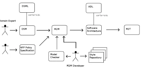
This section outlines the MDE tool chain and workflow proposed in this paper (see Figure 1). In our proposed approach, the domain expert creates a domain-specific model of the system, which conforms to a DSML. A user (who may or may not be the domain expert) chooses between a number of design trade-offs, expressed in terms of non-functional properties, which forms the NFP policy specification. This model (DSM) and specification are input into the M2M transformation engine, where the NFP policy is used to select between a number of trade-offs in the transformation. The output of this stage is a software architecture description which conforms to an ADL. This description can then be used to generate software arte-facts (e.g. code, CORBA Component Model deployment descriptors, Web Service Description Language) at the model-to-text (M2T) stage. While supported by this approach, mappings to multiple platforms and round-trip engineering are outside the scope of this paper.
The M2M transformation developer has access to a
repository of architectural styles in the form of reusable component and connector types. These are used while specifying the M2M transformation, to create the patterns in the target model. Section 5 describes in more detail what the customisable transformation specification might look like in a declarative M2M language. The developer has the option to reuse these styles without modification, use inher-itance to extend existing styles or develop target patterns that conform to no style. The M2M developer specifies trade-off (variability) points, where complementary styles can be applied (to provide the same functional behaviour) depending on the non-functional priorities of the system. A model checker is applied to the M2M specification to verify that each style has been applied correctly and that each trade-off choice leaves the system in a consistent state. When this is the case, the non-functional implications associated with the contrasting styles are reflected in additional options in the NFR policy specification. For example, in a trade-off between Client-Stateless-Server and Remote Session, the policy specification will show the options Scalability Vs. Simplicity of Client.
Note that this methodology does not dictate how styles are collected in the repository, and how it is verified that they offer the non-functional properties that are associated with them. Also, complementary styles need to be chosen that have non-functional implicationsrelativeto each other. Future work will focus on not just the non-functional impli-cations but also theapplicabilityof styles. While the NFPs related to a style are true in general, there are functional characteristics of systems that often make the application of a style unsuitable. For example, it is generally agreed that the pipe and filter style is unsuitable for systems that have frequent user interaction.
4. Software architecture and style description
4.1
Choice of ADL
An ADL is required to provide explicit support for modelling components, their interfaces, connectors and configurations. Component configuration should also support hierarchy, to handle models of anything but the most trivial systems. Many ADLs are tightly coupled to the platform that they were developed to describe. These have been classified as implementation constraining [7]. As our approach aims at targeting multiple platforms, it requires a non-implementation constraining ADL. Explicit support for software architecture styles is also required. Finally, precise behavioural semantics are necessary for facilitating analysis as well as capturing all the behaviour that a DSML specifies.
Figure 1. Proposed MDE Tool chain
used ADLs were considered: ACME [12], Rapide [6] and WRIGHT [1]. Rapide is a popular ADL, which has been used to model numerous real-world system and supports di-rect simulation of its specifications. It is based on poset se-mantics, with semantics definable for both components and connectors and is implementation-independent. Connectors are not first-class entities and are specified in-line, so are not named or reusable. Configuration is likewise done inline, which raises issues of scalability, and there is no support for styles.
ACME was initially designed as an architecture in-terchange language, and supported the lowest common denominator of other ADLs. It thus supports compo-nents, connectors and hierarchical configurations. It is implementation-independent and has been extended to ex-plicitly support styles [8]. While its simplicity is appealing, it lacks the semantics to be applicable to every domain. Despite this, it has good tool support, including analysis tools.
The WRIGHT ADL supports the description of compo-nents, connectors and configurations using CSP-like seman-tics. It is non-implementation constraining and has explicit support for styles with both structural and behavioural in-variants. WRIGHT thus satisfies all of the requirements stated above, and was selected for this initial study. How-ever, it has not been previously used to generate software artefacts.
4.2. Design trade-off case study
This section describes two complementary styles of replication, active and passive, and describes their structural invariants using WRIGHT. This case study assumes there is a model element in the DSML representing a server structure that requires replication. This model element can be mapped to either of the replication styles depending on the desired non-functional properties of the modelled
system. In the passive replication style, at any time there is one primary replica manager that handles communication to all front-ends. When the primary replica manager completes the operation, it sends a copy of the updated data to all the backups. If the primary fails, one of the backups is then promoted to act as the primary. In the active repli-cation scheme, front-ends multicast their request to every replica manager. Replica managers play equivalent roles, processing the request independently but also identically. If one crashes, there is no impact on performance as the remaining managers can still respond. Passive and active replication are illustrated in Figure 2.
the generic RequestResponse connector. This connector description is used for illustration purposes only:
Connector RequestResponse
Role FE= ¯request→response→FEu I
Role Server=request→¯response→Server]
I
Glue=FE.request→S¯erver.request→Glue Server.response→F¯E.response→Glue
]
I
The roles describe the pattern of interaction required of the two components attached to the connector. The glue indicates how the behaviour of the roles corresponds, and represents a full be-havioural specification of the connector. The FE role initiates the request (indicated by the overbar) and observes a response. It then makes an internal choice (indicated by theusymbol) be-tween making another request or successfully terminating (H
). An internal choice is a choice made without consulting the environ-ment, indicating that clients decide when to initiate a request. The second role observes the request and initiates a response. It then makes an external choice (]) between handling another request or successfully terminating. This external choice means that the server must react to its environment (the client), and handle re-quests when needed. The active replication style constraint can then be expressed thus:
∀comp:Components|T ype(comp) =ReplicaM anager; ∃conn:Connectors|T ype(conn) =RequestResponse
•r:Role;p:P ort|((comp, p)(conn, r))∈Attachments
which states that every component of the typeReplicaManager is attached to a connector of typeRequestResponse. Attachments is the set of all attachments in the configuration. Attachments are always expressed as a pair of pairs ((Component, Port)(Connector, Role)). A port of a component indicates an interaction that it can take part in. A component also includes a full behavioral specifica-tion, like Glue called Computation. This must match the behaviour specified in the Role of the Connector for the attachment to be valid. The passive replication style constraint can be expressed as:
∃primaryRM:
Components|T ype(primaryRM) =ReplicaM anager• ∀conn:Connectors|T ype(conn) =RequestResponse;
r:Role, p:P ort|((primaryRM, p)(conn, r)) ∈Attachments
which states that there exists a component of the type Repli-caManagerthat is attached to everyRequestResponseconnector. When these styles are added to the style repository, they are associ-ated with the non-functional implications which they have relative to their contrasting style (see Figure 5).
5. Specifying customisable transformations
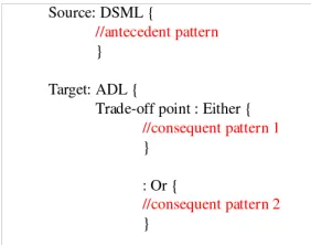
The previous section showed how software architectures and styles are described in the WRIGHT ADL. This section describes how they are used to create customisable transformations. Figure 3 illustrates how a transformation might be specified in a declar-ative M2M language. The either/or trade-off points behave like if/else constructs in a programming language, allowing multiple or options to be connected. In specifying the consequent patterns in ADL, the developer can reuse the pre-specified component and connector types available (e.g. ReplicaManager and RequestRe-sponse above).
Checking and compiling of the specification then occurs in three stages. Firstly, the transformation is checked that it is valid according to the rules of the M2M language. Secondly, each consequent pattern must, when applied, describe a consistent configuration. For example, the interaction (Computation in WRIGHT) that the component supports must match one of the roles specified in the connector. The WRIGHT ADL prescribes how this checking can be done. Finally, the developer can choose to check either/or consequent patterns for conformity to contrasting architectural styles. If both patterns conform to their respective styles, the non-functional implications associated with the styles are then reflected in additional options in the user policy specification.
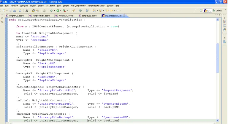
Supporting trade-offs in M2M transformations requires a small syntax extension to existing languages. Figure 4 shows an ATLAS transformation language (ATL) [5] rule that specifies a transformation from a model element conforming to the DWS metamodel to a group of model elements in the WrightADL metamodel. The code after the from keyword specifies the antecedent pattern, which in this case is aContextElementwith a boolean attributerequiresReplicationset to true. The consequent pattern (after the to keyword), creates seven model elements that create a configuration that meets the constraints imposed by the passive replication style. The rule is applied only once, and in natural language states that ‘if any ContextElement is encountered that requires replication, create a configuration that provides replication functionality in the software architecture.’ Three components of type ReplicaManager are created. One of these (namedPrimaryRM) is connected directly to the front end using a connector of typeRequestResponse. The two other replica managers (backupRM1 and backupRM2) are connected to the primary replica manager only, through connectors of type SynchroniseRM. The component FrontEnd is created in this example rule for illustration purposes only, and in a complete transformation specification would probably be created in another rule. The definition of the complementary rule replicatedCon-text2ActiveReplicationis omitted here for the sake of brevity.
Figure 2. Passive (left) and Active (right) Replication
Figure 3. Customisable Model-to-Model Transformation
the complex formal specification of component and connector be-haviour contained separately in the ADL repository, only being re-ferred to here using their type name. Once the ADL type has been defined in the repository, it can be completely reused in multiple transformation rules.
Figure 5 shows how the active replication style might be rep-resented in the style repository. The invariant is described in both natural language and using the preferred ADL. The non-functional implications of applying a style are always described relative to a direct parent or sibling in the tree of styles. In this case, Active and Passive Replication are siblings in the tree of data replication styles. Non-functional implications expressed are either positive or negative, indicated by a plus or minus sign.
6. Summary and future work
This paper proposed a novel MDE toolchain based around a customisable M2M transformation, which allows the selection of alternative software architectures depending on non-functional pri-orities. The M2M developer creates a transformation by reusing predefined components and connectors to produce patterns that conform to a software architecture style. The non-functional prop-erties of these styles are then presented to the modeller as options. The input to the transformation is a DSML that describes a family of software systems with variability in terms of NFR.
The tool chain offers many of the benefits associated with model-driven techniques: 1) it allows the system to be described using abstractions and notation from the problem domain, 2) it supports the application of proven best practices in design, 3) it fa-cilitates system analysis early in the software development lifecy-cle and 4) it automates the generation of software artefacts. These four benefits are often cited, but rarely delivered in an integrated tool chain.
6.1. Future work
Figure 4. Sample ATL transformation rule, creating a pattern that conforms to the passive replication style
Figure 5. Active replication entry in the style repository
References
[1] R. Allen.A Formal Approach to Software Architecture. PhD thesis, Carnegie Mellon, School of Computer Science, Jan-uary 1997. Issued as CMU Technical Report CMU-CS-97-144.
[2] R. T. Fielding. Architectural Styles and the Design of Network-based Software Architectures. PhD thesis, Informa-tion and Computer Science, University of California, Irvine, 2000.
[3] G. Grau and X. Franch. A Goal-Oriented Approach for the Generation and Evaluation of Alternative Architectures. In European Conference on Software Architecture, pages 139– 155. Springer-Verlag LNCS, 2007.
[4] A. Haase, M. Volter, S. Efftinge, and B. Kolb. Introduction to openArchitectureWare 4.1.2. InMDD Tool Implementers Forum, 2007.
[5] F. Jouault and I. Kurtev. Transforming Models with ATL. InSatellite Events at the MoDELS 2005 Conference, pages 128–138. Springer LNCS, 2005.
[6] D. C. Luckham, J. J. Kenney, L. M. Augustin, J. Vera, W. Mann, W. Mann, D. Bryan, and W. Mann. Specifi-cation and Analysis of System Architecture Using Rapide. IEEE Transactions on Software Engineering, 21(4):336– 355, 1995.
[7] N. Medvidovic and R. N. Taylor. A Classification and Com-parison Framework for Software Architecture Description Languages. IEEE Transactions on Software Engineering, 26(1):70–93, 2000.
[8] R. Monroe. Rapid Development of Custom Software Archi-tecture Design Environments. PhD thesis, Carnegie Mellon, School of Computer Science, 1999.
Conference on Software Architecture (ECSA), pages 325– 329. Springer-Verlag LNCS, 2007.
[10] OMG. MDA Guide. http://www.omg.org/docs/omg/03-06-01.pdf, 2003.
[11] B. Sch¨atz. Combining Product Lines and Model-Based De-velopment. Electronic Notes in Theoretical Computer Sci-ence (ENTCS), 182:171–186, 2007.
[12] B. Schmerl and D. Garlan. AcmeStudio: Supporting Style-Centered Architecture Development (Research Demonstra-tion). InProceedings of the 26th International Conference on Software Engineering (ICSE), 23-28 May 2004. [13] TCS. ModelMorf: A Model Transformer.