XVME-983
Software Support
Library
P/N 74983-001C
Xycom Revision Record
Revision Description Date
A Manual Released 11/90
B Manual Updated 5/92
C Manual Updated 11/93
Trademark Information
Brand or product names are registered trademarks of their respective owners.
Windows is a registered trademark of Microsoft Corp. in the United States and other countries.
Copyright Information
This document is copyrighted by Xycom Incorporated (Xycom) and shall not be reproduced or copied without expressed written authorization from Xycom.
TABLE OF CONTENTS
CHAPTER TITLE PAGE
1 INTRODUCTION
1.1 Manual Structure 1-1
1.2 Overview 1-1
1.2.1 VMEbus Boards Supported with C Language Subroutines 1-2
1.2.2 VMEbus Boards Supported with MS-DOS Drivers 1-3
1.3 Library Organization 1-4
1.4 Installation 1-5
1.4.1 \EXAMPLES Directory 1-5
1.4.2 \INCLUDE Directory 1-8
1.4.3 \LIB Directory 1-8
1.4.4 \SERIAL Directory 1-9
1.5 Development Notes 1-9
2 XVME GENERAL PURPOSE LIBRARY
2.1 Introduction 2-1
2.2 Real Mode Window 2-1
2.3 Interrupts 2-2
2.4 General Purpose Routines 2-2
2.4.1 Initial XVME Library 2-3
2.4.2 Initialize XVME Library 2-4
2.4.3 Release the VMEbus 2-4
2.4.4 Access the VMEbus 2-5
2.4.5 Set Real Mode Window 2-5
2.4.6 Read VMEbus Memory Through The Real Mode Window 2-6
2.4.7 Write VMEbus Memory Through The Real Mode Window 2-7
2.4.8 Read VMEbus Memory In Protected Mode 2-8
2.4.9 Write VMEbus Memory In Protected Mode 2-9
2.4.10 Set Interrupt Vector 2-10
2.4.11 Read Interrupt Vector 2-10
2.4.12 Mask the Interrupt Controller 2-11
2.4.13 Disable VME Interrupts 2-11
2.4.14 Enable VME Interrupts 2-11
2.4.15 Set NMI Interrupt Vector 2-12
2.4.16 Read NMI Vector 2-12
2.4.17 Enable Auxiliary NMI 2-13
2.4.18 Disable Auxiliary NMI 2-13
2.4.19 Generate VMEbus Interrupt 2-14
2.4.20 Enable the Watchdog Timer 2-14
Table of Contents
CHAPTER TITLE PAGE
3 MODULE LIBRARY: DIGITAL I/O BOARDS
3.1 Introduction 3-1
3.2 XVME-200/290 Digital I/O Module 3-2
3.2.1 Initialize 3-2
3.2.2 Set the Counter Pre-Load Register 3-3
3.2.3 Set Port A Direction 3-3
3.2.4 Set Port B Direction 3-4
3.2.5 Set Port A Sub Mode 3-4
3.2.6 Set Port B Sub Mode 3-5
3.2.7 Read a Byte 3-5
3.2.8 Write a Byte 3-6
3.2.9 Interrupt Example 3-6
3.3 XVME-201 Digital I/O Module 3-7
3.3.1 Initialize 3-8
3.3.2 Set Port Direction 3-8
3.3.3 Set Port C Direction 3-9
3.3.4 Set the Counter Pre-Load Register 3-9
3.3.5 Read a Byte 3-10
3.3.6 Write a Byte 3-10
3.4 XVME-202 PAMUX Controller 3-11
3.4.1 Initialize 3-11
3.4.2 Read a Byte 3-12
3.4.3 Write a Byte 3-12
3.4.4 Reset 3-13
3.5 XVME-212 Digital Input Module 3-14
3.5.1 Initialize 3-14
3.5.2 Read a Byte 3-15
3.5.3 Write a Byte 3-15
3.5.4 Read a Word 3-16
3.5.5 Write a Word 3-16
3.5.6 Read Scan 3-17
3.5.7 Read Word Scan 3-18
3.5.8 Interrupt Disable 3-18
3.5.9 Read a Channel 3-19
XVME-983 Manual November 1993
CHAPTER TITLE PAGE
3.6.9 Reset 3-24
3.7 XVME-240 Digital I/O Module 3-25
3.7.1 Reset 3-25
3.7.2 Read a Byte 3-26
3.7.3 Read a Word 3-26
3.7.4 Write a Byte 3-27
3.7.5 Write a Word 3-27
3.7.6 Interrupt Example 3-28
3.8 XVME-244 Digital Output Module 3-29
3.8.1 Read a Channel 3-29
3.8.2 Read a Byte 3-30
3.8.3 Read a Word 3-30
3.8.4 Read All 3-31
3.8.5 Write a Channel 3-31
3.8.6 Write a Byte 3-32
3.8.7 Write a Word 3-32
3.8.8 Write All 3-33
3.8.9 Reset 3-33
3.9 XVME-260 Digital Output Module 3-34
3.9.1 Read a Channel 3-34
3.9.2 Read a Byte 3-35
3.9.3 Read a Word 3-35
3.9.4 Read All 3-36
3.9.5 Write a Channel 3-36
3.9.6 Write a Byte 3-37
3.9.7 Write a Word 3-37
3.9.8 Write All
4 MODULE LIBRARY: ANALOG I/O BOARDS
4.1 Introduction 4-1
4.2 XVME-500/590 Analog Input Module 4-2
4.2.1 Read a Byte 4-2
4.2.2 Write a Byte 4-3
4.2.3 Wait 4-3
4.2.4 Force an A/D Conversion 4-4
4.2.5 Set Interrupt 4-4
4.2.6 Set Conversion Mode 4-5
4.2.7 Reset 4-5
4.2.8 Analog to Digital 4-6
4.2.9 Set Gain Factor 4-7
4.2.10 Read Gain Factor 4-8
Table of Contents
CHAPTER TITLE PAGE
4.3.1 Channel Output 4-10
4.4 XVME-530 Analog Output Module 4-11
4.4.1 Read a Byte 4-11
4.4.2 Write a Byte 4-12
4.4.3 Reset 4-12
4.4.4 Wait 4-13
4.4.5 Channel Output 4-13
4.5 XVME-540 Analog I/O Module 4-14
4.5.1 Read a Byte 4-14
4.5.2 Write a Byte 4-15
4.5.3 Wait 4-15
4.5.4 Force an A/D Conversion 4-16
4.5.5 Set Interrupt 4-16
4.5.6 Set Conversion Mode 4-17
4.5.7 Reset 4-17
4.5.8 Analog to Digital 4-18
4.5.9 Set Gain Factor 4-18
4.5.10 Read Gain Factor 4-19
4.5.11 Channel Output 4-19
4.6 XVME-560 Analog I/O Module 4-20
4.6.1 Read a Byte 4-21
4.6.2 Write a Byte 4-21
4.6.3 Wait 4-22
4.6.4 Force an A/D Conversion 4-22
4.6.5 Set Interrupt 4-23
4.6.6 Set Conversion Mode 4-23
4.6.7 Reset 4-24
4.6.8 Analog to Digital 4-24
4.6.9 Set Gain Factor 4-25
4.6.10 Interrupt Example 4-26
4.7 XVME-566 High-Performance Analog Input Module 4-27
4.7.1 Read a Byte 4-27
4.7.2 Write a Byte 4-28
4.7.3 Write a Word 4-28
4.7.4 Set Sample Clock 4-29
XVME-983 Manual November 1993
CHAPTER TITLE PAGE
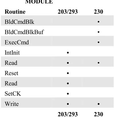
5 MODULE LIBRARY: COUNTER MODULES
5.1 Introduction 5-1
5.2 XVME-203/293 Counter Module 5-2
5.2.1 Read a Byte 5-2
5.2.2 Write a Byte 5-3
5.2.3 Reset 5-3
5.2.4 Set Clock 5-4
5.2.5 Initialize Interrupt 5-4
5.2.6 Interrupt Example 5-5
5.3 XVME-230 Intelligent Counter Module 5-5
5.3.1 Read a Byte 5-6
5.3.2 Write a Byte 5-6
5.3.3 Build a Command Block 5-7
5.3.4 Build a Command Block with Operand Buffer 5-7
5.3.5 Execute Command Block 5-8
5.3.6 Interrupt Example 5-8
6 MODULE LIBRARY:
MS-DOS COMMUNICATION DRIVERS
6.1 Introduction 6-1
6.2 VMEbus Base Address Jumpers 6-1
6.3 Address Modifier Jumpers 6-1
6.4 CONFIG.SYS 6-2
6.4.1 File Name Field 6-2
6.4.2 Base Address Field (bbbb) 6-3
6.4.3 Channel Number (c) 6-3
6.4.4 Speed or Baud Rate (ss) 6-3
6.4.5 Parity (p) 6-3
6.4.6 Databits (d) 6-3
6.4.7 Stopbits (q) 6-3
6.5 Examples 6-4
6.6 Troubleshooting 6-4
7 XVME PC/AT INTERRUPT ROUTINES
7.1 Introduction 7-1
7.2 Auxiliary Non-maskable Interrupt 7-1
7.3 BERR 7-4
Table of Contents
LIST OF TABLES
TABLE TITLE PAGE
2-1 Reserved Constants 2-3
3-1 Digital I/O Routine Matrix 3-1
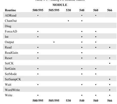
4-1 Analog I/O Routine Matrix 4-1
Chapter 1 - INTRODUCTION
1.1 MANUAL STRUCTURE
This manual is designed to help you understand and use the Xycom XVME-983 MS-DOS Software Support Library. Chapter 1 gives an overview of the package and directions on how to start using the library. Chapters 2-8 each describe a set of routines for a specific category of XVME boards.
This outline of the manual structure will help you find the specific sections containing information relevant to your system needs:
Chapter 1 Introduction
Chapter 2 XVME General Purpose Routines Chapter 3 Module Library: Digital I/O Boards Chapter 4 Module Library: Analog I/O Boards Chapter 5 Module Library: Counter Modules Chapter 6 Module Library: Bitbus Module
Chapter 7 Module Library: MS-DOS Communication Drivers Chapter 8 XVME PC/AT Interrupt Routines
1.2 OVERVIEW
The XVME-983 MS-DOS Software Support Library (MS-DOS SSL) is a collection of routines designed to provide a consistent, easy-to-use tool for developing application programs for Xycom VMEbus board products. The routines in this library contain the low-level coding necessary to configure the supported hardware modules and perform I/O. You spend less time and effort programming since you do not need to write any module-specific codes or program any routines.
The XVME-983 MS-DOS SSL is distributed on one 3.5-inch, 1.44 Mbyte MS-DOS diskette. It runs on Xycom VMEbus PC/AT processor modules (XVME-674, 677, 678 and 688). The README.DOC file describes the contents of the disk and the location of specific files.
In addition to XVME module-specific routines, the SSL contains general purpose routines which, when run on PC/AT processor modules, can access either Xycom or non-Xycom hardware. Real and Protected mode routines provide access to VMEbus address spaces. There are also routines to set up, enable, and disable interrupts and their respective handlers.
Chapter 1 - Introduction
The SSL diskette contains:
• Object code libraries to be linked with application programs • Device drivers for Xycom VME communication boards • Sample programs for every VME board supported • Source code and make files for all programs and libraries
The object code libraries contain routines needed to communicate with Xycom VME boards. The object code libraries are available in all memory models supported by Microsoft C (version 7.0), Microsoft QuickC (version 2.5), and Borland Turbo C++ (version 3.0). You can simply link in the memory model library corresponding to your configuration to develop an application.
The device drivers for Xycom VME communication boards are compatible with MS-DOS version 3.0 or higher. The drivers provide all the necessary facilities to use these boards as additional serial I/O modules.
The sample programs in the Software Support Library (SSL) use each of the defined library routines. The SSL specifies all source files and make files needed to build any of the sample programs. You can use these source files and make files to integrate the SSL into application programs written for your Xycom products.
Most sample programs in this manual were compiled using Microsoft C 7.0. The \EXAMPLES\QCEXAMPL files explain how to use these routines with the Microsoft QuickC compiler; the \EXAMPLES\TCEXAMPL files pertain to the Borland Turbo C++ compiler (Section 1.2.1). If you want to recompile the example programs using Borland Turbo C++, you must refer to your compiler manual and the information in the appropriate directory to achieve the same results.
1.2.1 VMEbus Boards Supported with C Language Subroutines
PC/AT Processors:
XVME-674 33 MHz 80486DX or 66 MHz 80486DX2 processor; 4, 16, or 32 Mbytes DRAM; IDE hard disk and floppy disk controllers; two serial ports and one parallel port
XVME-677 33 M;Hz 80486SX; 4, 16, or 32 Mbytes DRAM; IDE hard disk and floppy disk controllers; Super VGA graphics controller; two serial ports; and one parallel port.
XVME-983 Manual November 1993
Digital I/O:
XVME-200/29032-channel DIO with interrupts
XVME-201 48-channel DIO without interrupts XVME-202 PAMUX controller
XVME-212 32-channel isolated digital input module with change-of-state detection XVME-220 32-channel isolated digital output module
XVME-240 80-channel digital TTL I/O module XVME-244 64-channel isolated digital I/O module XVME-260 32-channel relay output module
Analog I/O:
XVME-500/59016SE/8DI-channel analog input XVME-505/5954-channel analog output
XVME-530 8-channel isolated analog output module
XVME-540 32/16-channel analog input, 4-channel analog output, 12-bit A/D XVME-560 64/32-channel analog input module
XVME-566 100 KHz, 32/16-channel analog input module
Counter Modules:
XVME-203/29310-channel counter
XVME-230 16-channel intelligent counter module
1.2.2 VMEbus Boards Supported with MS-DOS Drivers
Communication Modules:
XVME-400/4904-channel RS-232C serial I/O
XVME-401/4914-channel RS-422A/RS-485 serial I/O
Chapter 1 - Introduction
1.3 LIBRARY ORGANIZATION
Each library module name references the type and memory model of the compiler which it is designed to support. The library names are all set up in this format:
XVME{compiler type}{memory model}.{library extension}
For example, XVMEMSCC.LIB is the XVME compact memory model library for the Microsoft C 7.0 compiler. The memory models and library extensions are compiler specific, as described below:
For Microsoft C 7.0
XVMEMSCS.LIB for small memory model XVMEMSCC.LIB for compact memory model XVMEMSCM.LIB for medium memory model XVMEMSCL.LIB for large memory model XVMEMSCH.LIB for huge memory model
For Microsoft QuickC 2.5
XVMEMQCS.LIB for small memory model XVMEMQCC.LIB for compact memory model XVMEMQCM.LIB for medium memory model XVMEMQCL.LIB for large memory model
For Borland Turbo C++ 3.0
XVME-983 Manual November 1993
1.4 INSTALLATION
You do not have to load the SSL files onto the hard disk to run the routines, but we suggest you install the files as directed in this chapter.
The directories on the XVME-983 SSL diskette are:
\EXAMPLES \INCLUDE \LIB \SERIAL
The INSTALL.BAT file on the SSL diskette can be used to create these directories (and their subdirectories) in a target directory and copy the files from the SSL diskette into these directories.
To install XVME983 on a hard disk directory, follow these steps (user input shown in boldface):
1. At the C:> prompt, type MD XVME983 to create the XVME983 directory.
2. Type CD XVME983 to get into the directory.
3. Put diskette into drive A.
4. Type A:INSTALL to run the install batch file.
Read the note in the section describing the \INCLUDE directory for additional installation instructions.
1.4.1 \EXAMPLES DIRECTORY
The \EXAMPLES directory contains example programs for Xycom XVME modules. This directory is divided into the following subdirectories:
NOTE
Chapter 1 - Introduction
ANALOG.xxx Menu-driven program that allows users to call each of the routines. Users are prompted for the parameters for the routines. Help screens are provided to describe the routines and their parameters. The routines physically read and write to the XVME-5xx boards in the VMEbus. X5xxDISP.xxx Modules linked into ANALOG.xxx for each of the XVME-5xx boards. X5xxTEXT.H Include files for X5xxDISP.C files.
ALOG.MAK Make file for ANALOG.EXE.
X5xxINT.xxx Programs that show how to use the routines/boards with interrupts. AINT.MAK Make and Link file for all X5xxINT.EXE programs.
\EXAMPLES\BITBUS
BITBUS.xxx A program that shows how to use the XVME-402 with interrupts. BITPOLL.xxx A program that shows how to use the XVME-402 in polled mode. BIT.MAK Make and Link file for BITBUS and BITPOLL.
\EXAMPLES\COUNTER
COUNTER.xxx Menu-driven program that lets users call each of the routines. Users are prompted for the routine parameters. Help screens are provided to describe the routines and their parameters. The routines physically read and write to the XVME-2xx boards on the VMEbus.
X2xxDISP.xxx Modules linked into COUNTER.xxx for each of the XVME-2xx boards. X2xxTEXT.H Include files for X2xxDISP.C files.
COUNT.MAK Make file for COUNTER.EXE.
X2xxINT.xxx Programs that show how to use the routines/boards with interrupts. CINT.MAK Make and Link file for all X2xxINT.EXE programs.
\EXAMPLES\DIGITAL
DIGITAL.xxx Menu-driven program that lets users call each of the routines. Users are prompted for the routine parameters. Help screens are provided to describe the routines and their parameters. The routines physically read and write to the XVME-2xx boards in the VME bus.
X2xxDISP.xxx Modules linked into DIGITAL.xxx for each of the XVME-2xx boards. X2xxTEXT.H Include files for X2xxDISP.C files.
XVME-983 Manual November 1993
\EXAMPLES\INCLUDE
This directory contains include files used by the utility routines for the example programs. In order for the make files and C programs to compile, the environmental variable INCLUDE should be set up to include this directory. This is done by executing the following command (as long as XVME983 was created in the root directory):
SET INCLUDE=%INCLUDE%;c:\XVME983\EXAMPLES\INCLUDE
\EXAMPLES\INT
ANMI.xxx A program that shows how to handle NMI interrupts.
BERR.xxx A program that shows how to handle BUS ERROR interrupts. WDTIMER.xxx A program showing how to handle interrupts from the watch-dog-timer.
DUALPORT.xxx A program showing how to handle dual-port interrupts.
\EXAMPLES\QCEXAMPL\IDE(compiled with Microsoft QuickC 2.5)
QCEXAM.BATA batch file that shows how to invoke the QuickC interactive environment when integrating the XVME-983 software support library.
\EXAMPLES\QCEXAMPL\CMDLINE
QCEXAM.BATA batch file that shows how to make a QuickC program in the non-interactive environment when integrating the XVME-983 software support library.
\EXAMPLES\TCEXAMPL (compiled with Borland Turbo C++ 3.0)
TCEXAM.BAT A batch file that shows how to invoke the Turbo C interactive environment when integrating the XVME-983 software support library.
\EXAMPLES\UTILS
Chapter 1 - Introduction
1.4.2 \INCLUDE DIRECTORY
The \INCLUDE directory contains include files used by the library routines and the example programs. In order for the make files and C programs to compile, the environmental variable INCLUDE should be set up to include this directory. This is done by or executing the following command (as long as XVME983 was created in the root directory):
SET INCLUDE=%INCLUDE%;c:\XVME983\INCLUDE
1.4.3 \LIB DIRECTORY
The \LIB directory contains the XVME-983 software support library. Included in the \LIB\SOURCES subdirectory is the source code and make files necessary to recreate the libraries. This subdirectory contains the following files:
BTCLIBS.BAT Batch file that builds the XVMEBTCx.LIB library files.
BUILDALL.BAT Batch file that builds all the XVMExxxx.xxx library files. MQCLIBS.BAT Batch file that builds the XVMEMQCx.LIB library files. MSCLIBS.BAT Batch file that builds the XVMEMSCx.LIB library files.
The \LIB\SOURCES directory is further divided into the following subdirectories:
\LIB\SOURCES\ANALOG
XVME5xx.xxx Support routines for each board.
\BTCLIB\ANALLIB.MAK Make file for the support routines (Turbo C). \MQCLIB\ANALLIB.MAK Make file for the support routines (QuickC). \MSCLIB\ANALLIB.MAK Make file for the support routines (MSC).
\LIB\SOURCES\COUNTER
XVME2xx.xxx Support routines for each board.
\BTCLIB\COUNTLIB.MAK Make file for the support routines (Turbo C). \MQCLIB\COUNTLIB.MAK Make file for the support routines (QuickC). \MSCLIB\COUNTLIB.MAK Make file for the support routines (MSC).
\LIB\SOURCES\DIGITAL
XVME2xx.xxx Support routines for each board.
XVME-983 Manual November 1993
\LIB\SOURCES\XVME
XVME.C VMEbus general purpose routines.
P286MT.ASM 80286 protected mode memory transfer routine. P386MT.ASM 80386 protected mode memory transfer routine.
NONANSI.ASM Rewritten C library routines that were not ANSI standard. \BTCLIB\XVMELIB.MAK Make file for the support routines (Turbo C).
\MQCLIB\XVMELIB.MAK Make file for the support routines (QuickC). \MSCLIB\XVMELIB.MAK Make file for the support routines (MSC).
1.4.4 \SERIAL DIRECTORY
The \SERIAL directory contains the files for the XVME-400 and 428 device drivers. This directory is divided into subdirectories:
\SERIAL\X40X
X40X.SYS Device driver for XVME-400/401 boards.
\SOURCE Subdirectory containing C and assembly source code and a make file for the driver. \SERIAL\X42X
X42X.SYS Device driver for XVME-428
\SOURCE Subdirectory containing C and assembly source code and a make file for the driver.
1.5 DEVELOPMENT NOTES
Development was performed on a 80486 AT machine using DOS 5.0.
Development tools were as follows:
For Microsoft (R) C: Those supplied with version 7.0. CL.EXE, LINK.EXE, LIB.EXE, MAKE.EXE, and MASM 5.1
For Microsoft (R) QUICKC: Those supplied with version 2.5. QC.EXE, QCL.EXE, LINK.EXE, LIB.EXE, MAKE.EXE, and MASM 5.1
Chapter 2 - XVME GENERAL PURPOSE LIBRARY
2.1 INTRODUCTION
These general purpose routines are designed to let users easily program Xycom's VMEbus PC/AT processor modules (see Section 1.2.1). This chapter deals with two areas: transferring data to and from the VMEbus address space and supporting VMEbus interrupts. These routines form the basis of all of the specialized routines found in the XVME-983 MS-DOS Software Support Library.
2.2 REAL MODE WINDOW
Some of the general purpose routines use the Real Mode Window (RMW). The RMW provides a mechanism for addressing the entire VMEbus memory space without the need to run the CPU in protected mode. It is 64 Kbytes long and resides at addresses 0E0000-0EFFFF. The window can be configured, via software, to address one of the following: VMEbus Short I/O, VMEbus Standard Address Space, VMEbus IACK Space, or EPROM. You can also configure some PC/AT modules to address VMEbus Extended Address Space. Refer to your PC/AT module manual to determine if you can access Extended Address Space.
When the RMW is configured for VMEbus Short I/O, the 64 Kbyte Short I/O Address Space may be accessed through the 64 Kbyte window. Any references to the RMW will map directly into the VMEbus Short I/O Space.
When the RMW is configured for VMEbus Standard Address Space, the 64 Kbyte window may be used to access any 64 Kbyte block of the VMEbus Standard Address space. In this mode, the 16 Mbyte Standard Address Space is logically divided into 256 64 Kbyte blocks that are configured through software.
When the RMW is configured for VMEbus IACK, a byte read from specific locations in the RMW will cause the PC/AT processor to perform a VMEbus IACK cycle. The data returned from the byte read will be the status ID vector returned from the responding interrupter.
When the RMW is configured for EPROM, the lower 64 Kbytes of the PC/AT's EPROM will appear in the window. This is the mode selected after reset. This mode is compatible with the IBM PC/AT architecture.
Chapter 2 - XVME General Purpose Library
2.3 INTERRUPTS
All Xycom VMEbus PC/AT processor modules are capable of handling interrupts on all seven VMEbus interrupt levels. The XVME-674 and 677 also contain a VMEbus interrupter circuit. This local interrupter allows the local CPU to generate a VMEbus interrupt on any of the seven VMEbus interrupt levels.
2.4 GENERAL PURPOSE ROUTINES
The routines in this section are designed to either process interrupts or transfer memory on any of Xycom VMEbus PC/AT processor modules. Functions unique to a specific CPU are called out.
The parameters you use when implementing the general purpose routines must match the type expected by the routine. If you pass an invalid parameter, the routine will operate erratically.
Parameters:
AccessType = 1 byte Address = 4 bytes Block64K = 2 bytes BlockSize = 2 bytes Buffptr = Pointer to 1st byte of data buffer CPU = 2 bytes EnableFlag = 1 byte EndianType = 1 byte IntHandler = 4 bytes IRQLevel = 1 byte
Level = 1 byte TimeOut = 1 byte
XVME-983 Manual November 1993
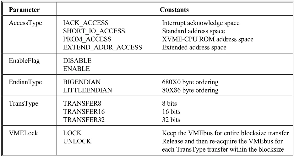
[image:21.612.69.537.125.373.2]Certain parameters for the general purpose routines have reserved constants, as shown in Table 2-1.
Table 2-1. Reserved Constants
Parameter Constants
AccessType IACK_ACCESS Interrupt acknowledge space SHORT_IO_ACCESS Standard address space
PROM_ACCESS XVME-CPU ROM address space EXTEND_ADDR_ACCESS Extended address space
EnableFlag DISABLE ENABLE
EndianType BIGENDIAN 680X0 byte ordering LITTLEENDIAN 80X86 byte ordering
TransType TRANSFER8 8 bits TRANSFER16 16 bits TRANSFER32 32 bits
VMELock LOCK Keep the VMEbus for entire blocksize transfer UNLOCK Release and then re-acquire the VMEbus for
each TransType transfer within the blocksize
These constants are defined in the file \INCLUDE\XVMEDEFS.H.
Source Code Location:\LIB\SOURCES\XVME\XVME.C
2.4.1 Initial XVME Library
Syntax:
AutoInitLib()
Function:
Dynamically determines which XVME-CPU module is being used and initializes the XVME SSL. This routine or the InitLib routine must be called initially for the library to function correctly.
Return Value:
Type of CPU module (674, 677, 678, or 688)
Chapter 2 - XVME General Purpose Library
Where:
CPU = Type of XVME CPU module (674, 677, 678, or 688)
Function:
This routine initializes the XVME SSL for a particular XVME CPU model. It must be called initially with the appropriate CPU value for the library to function correctly.
Return Value: None
2.4.3 Release the VMEbus
Syntax:
ReleaseVMEBus()
Function:
This routine releases the VMEBus from CPU control.
Return Value: None
2.4.4 Access the VMEbus
Syntax:
LockVMEBus(TimeOut)
Where:
TimeOut = Amount of time to wait for the bus
Function:
XVME-983 Manual November 1993
Where:
AccessType = Type of VMEbus access desired
IACK_ACCESS - interrupt acknowledge space SHORT_IO_ACCESS - short I/O space
STAND_ADDR_ACCESS - standard address space PROM_ACCESS - XVME-CPU ROM address space EXTEND_ADDR_ACCESS - extended address space (XVME-674, 677)
Block64 = Which 64 Kbyte block to map in if standard or extended access is desired.
Function:
This routine maps the Real Mode Window (0xE0000 - 0xEFFFF) to the desired VMEbus address space.
Chapter 2 - XVME General Purpose Library
2.4.6 Read VMEbus Memory Through The Real Mode Window
Syntax:
ReadVMEBusMemoryRM(Buffptr,TransType,EndianType,BlockSize,AccessType,Address, VMELock)
Where:
Buffptr = A byte pointer to the local storage area TransType = Type of data transfer
TRANSFER8 - 8 bits TRANSFER16 - 16 bits TRANSFER32 - 32 bits
EndianType = BIGENDIAN(680x0) or LITTLEENDIAN(80x86) BlockSize = Number of bytes to read (1 to 64K)
AccessType = Type of VMEbus access
IACK_ACCESS - Interrupt Acknowledge Space SHORT_IO_ACCESS - Short I/O Space
STAND_ADDR_ACCESS - Standard Address Space PROM_ACCESS - XVME-CPU Local EPROM Space EXTEND_ADDR_ACCESS - Extended Address Space Address = Specifies starting address for the transfer (32-bit address)
VMELock = Set TRUE to lock the VMEbus for the entire BlockSize transfer. Else the VMEBus will be locked and then released for each transfer within BlockSize.
Function:
This routine reads a block of memory on the VMEbus through the Real Mode Window (0xE0000 -0xEFFFF). This routine cannot be used to read the local dual-port memory on the PC/AT processor.
Return Value:
XVME-983 Manual November 1993
2.4.7 Write VMEbus Memory Through The Real Mode Window
Syntax:
WriteVMEBusMemoryRM(Buffptr,TransType,EndianType,
BlockSize,AccessType,Address,VMELock)
Where:
Buffptr = A byte pointer to the local storage area TransType = Type of data transfer
TRANSFER8 - 8 bits TRANSFER16 - 16 bits TRANSFER32 - 32 bits
EndianType = BIGENDIAN(680x0) or LITTLEENDIAN(80x86) BlockSize = Number of bytes to write (1 to 64K)
AccessType = Type of VMEbus access
IACK_ACCESS - Interrupt Acknowledge space SHORT_IO_ACCESS - Short I/O Space
STAND_ADDR_ACCESS - Standard Address Space PROM_ACCESS - XVME-CPU EPROM Address Space EXTEND_ADDR_ACCESS - Extended Address Space Address = Specifies starting address for the transfer (32-bit address)
VMELock = Set TRUE to lock the VMEbus for the entire BlockSize transfer. Else the VMEBus will be locked and then released for each transfer within BlockSize.
Function:
This routine writes a block of memory out on the VMEbus through the Real Mode Window (0xE0000 - 0xEFFFF). This routine cannot be used to write to local dual port memory.
Return Value:
Chapter 2 - XVME General Purpose Library
2.4.8 Read VMEbus Memory In Protected Mode
Syntax:
ReadVMEBusMemoryPM(Buffptr,TransType,EndianType,BlockSize,Address,VMELock)
where:
Buffptr = A byte pointer to the local storage area TransType = Type of data transfer
TRANSFER8 - 8 bits TRANSFER16 - 16 bits TRANSFER32 - 32 bits
EndianType = BIGENDIAN(680x0) or LITTLEENDIAN(80x86) BlockSize = Number of bytes to read (1 to 64K)
Address = Specifies starting address for the transfer (32-bit address)
VMELock = Set TRUE to lock the VMEbus for the entire BlockSize transfer. Else the VMEBus will be locked and then released for each transfer within BlockSize.
Function:
This routine reads a block of memory out on the VMEbus with the CPU in Protected Mode. This routine can be used to read from local dual-port memory.
Return Value:
Zero if successful; non-zero if not
NOTE
XVME-983 Manual November 1993
2.4.9 Write VMEbus Memory In Protected Mode
Syntax:
WriteVMEBusMemoryPM(Buffptr,TransType,EndianType,BlockSize,Address,VMELock)
Where:
Buffptr = A byte pointer to the local storage area TransType = Type of data transfer
TRANSFER8 - 8 bits TRANSFER16 - 16 bits TRANSFER32 - 32 bits
EndianType = BIGENDIAN(680x0) or LITTLEENDIAN(80x86) BlockSize = Number of bytes to write (1 to 64K)
Address = Specifies starting address for the transfer (32-bit address)
VMELock = Set TRUE to lock the VMEbus for the entire BlockSize transfer. Else the VMEBus will be locked and then released for each transfer within BlockSize.
Function:
This routine writes a block of memory out on the VMEbus with the CPU in Protected Mode. This routine can be used to write to local dual-port memory.
Return Value:
Zero if successful; non-zero if not
NOTE
Chapter 2 - XVME General Purpose Library
2.4.10 Set Interrupt Vector
Syntax:
SetIntVect(IRQLevel, IntHandler)
Where:
IRQLevel = AT IRQ (0-15) level whose interrupt vector is to be replaced. IntHandler = Address of user-defined interrupt handler
Function:
This routine sets the desired IRQ (0 - 15) vector to point to the user-defined interrupt handler. It returns the IRQ vector that is being replaced so it can be restored at a later time if desired.
Return Value:
Address of original IRQ vector
2.4.11 Read Interrupt Vector
Syntax:
ReadIntVect(IRQLevel)
Where:
IRQLevel = AT IRQ (0-15) level whose interrupt vector is to be read
Function:
This routine returns the current interrupt vector for the desired IRQ (0 - 15) level.
Return Value:
Address of IRQ vector
2.4.12 Mask the Interrupt Controller
Syntax:
Mask8259(IRQLevel, EnableFlag)
XVME-983 Manual November 1993
2.4.13 Disable VME Interrupts
Syntax:
DisableVMEInterrupts()
Function:
This routine disables the AT Auxiliary Maskable Interrupts used for VME interrupt levels 1-7 and the dual-port interrupt.
Return Value: None
2.4.14 Enable VME Interrupts
Syntax:
EnableVMEInterrupts()
Function:
This routine enables the AT Auxiliary Maskable Interrupts used for VME interrupt levels 1-7 and the dual-port interrupt.
Chapter 2 - XVME General Purpose Library
2.4.15 Set NMI Interrupt Vector
Syntax:
SetNMIVect(IntHandler)
Where:
IntHandler = Address of user-defined interrupt handler.
Function:
This routine sets the NMI vector to point to the user-defined interrupt handler. It returns the NMI vector that is being replaced so it can be restored at a later time if desired.
Return Value:
Address of the original NMI vector
2.4.16 Read NMI Vector
Syntax:
ReadNMIVect()
Function:
This routine returns the current NMI interrupt vector.
Return Value:
XVME-983 Manual November 1993
2.4.17 Enable Auxiliary NMI
Syntax:
EnableNMIInt()
Function:
This routine enables Auxiliary NMIs.
Return Value: None
2.4.18 Disable Auxiliary NMI
Syntax:
DisableNMIInt()
Function:
This routine disables Auxiliary NMIs.
Return Value: None
2.4.19 Generate VMEbus Interrupt
Syntax:
GenVMEBusInt(Level,Vector)
Where:
Level = VMEbus interrupt level (1-7) Vector = Interrupt vector (0-255)
Function:
This routine generates a VMEbus interrupt on the specified level. An error value will be returned if the XVME-CPU board cannot generate a VMEbus interrupt.
Return Value:
Zero if successful; non-zero if not
NOTE
Chapter 2 - XVME General Purpose Library
2.4.20 Enable the Watchdog Timer
Syntax:
EnableWDTimer()
Function:
This routine enables the Watchdog Timer.
Return Value: None
NOTE
XVME-983 Manual November 1993
2.4.21 Disable the Watchdog Timer
Syntax:
DisableWDTimer()
Function:
This routine disables the Watchdog Timer.
Return Value: None
2.4.22 Strobe the Watchdog Timer
Syntax:
StrobeWDTimer()
Function:
This routine retriggers the Watchdog Timer. This routine must be executed at least once every 150 ms to keep the Watchdog Timer from generating an Auxiliary NMI (if enabled).
Return Value: None
NOTE
This function is not available on the XVME-678 or 688.
NOTE
Chapter 2 - XVME General Purpose Library
2.4.23 Reset the Watchdog Timer
Syntax:
ResetWDTimer()
Function:
This routine resets the Watchdog Timer after it has timed out.
Return Value: None
NOTE
Chapter 3 - MODULE LIBRARY: DIGITAL I/O BOARDS
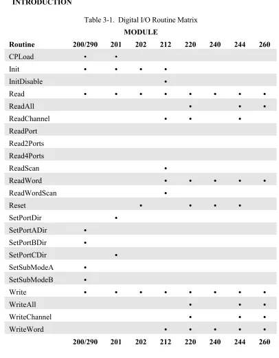
[image:35.612.101.507.166.686.2]3.1 INTRODUCTION
Table 3-1. Digital I/O Routine Matrix
MODULE
Routine 200/290 201 202 212 220 240 244 260
CPLoad • •
Init • • • •
InitDisable •
Read • • • • • • • •
ReadAll • • •
ReadChannel • • •
ReadPort Read2Ports Read4Ports
ReadScan •
ReadWord • • • • •
ReadWordScan •
Reset • • • •
SetPortDir •
SetPortADir •
SetPortBDir •
SetPortCDir •
SetSubModeA •
SetSubModeB •
Write • • • • • • • •
WriteAll • • •
WriteChannel • • •
WriteWord • • • • •
Chapter 3 - Module Library: Digital I/O Boards
3.2 XVME-200/290 DIGITAL I/O MODULE
The XVME-200 is a Digital I/O Module consisting of a VMEbus interface, two 68230 PI/T chips, and TTL buffers. The two PI/T chips provide 32 bits of digital I/O. The XVME-200 provides VMEbus interrupts and makes the PI/T timer available to users. The XVME-290 is a 6U version of the XVME-200 with the I/O routed to the VMEbus P2 connector.
The parameters used in the XVME-200/290 routines must match the type expected by the routine. If you pass an invalid parameter, the routine will operate erratically.
Parameters:
ByteData = 1 byte Direction = 1 byte PITNum = 1 byte Register = 2 byte SubMode = 1 byte TimerVal = 4 bytes X200Base = 2 bytes
Source Code Location:LIB\SOURCES\DIGITAL\XVME200.C
The routines in the following sections are available to the user in the XVME-983 Software Support Library.
3.2.1 Initialize
Syntax:
X200Init(X200Base)
Where:
X200Base = board address in VMEbus short I/O space
Function:
This function initializes Port C and Data Direction Registers on both PI/T chips to prevent unintentional interrupts.
MS-DOS Software Support Library November 1993
3.2.2 Set the Counter Pre-Load Register
Syntax:
X200CPLoad(X200Base,PITNum,TimerVal)
Where:
X200Base = Board address in VMEbus short I/O space PITNum = Number of PI/T chip (0 or 1)
TimerVal = Value to write into register (24 bit)
Function:
This routine writes a value between 0 and 16,777,215 to the Counter Pre-Load Register of the indicated PI/T chip.
Return Value: None
3.2.3 Set Port A Direction
Syntax:
X200PortADir(X200Base,PITNum,Direction)
Where:
X200Base = Board address in VMEbus short I/O space PITNum = Number of PI/T chip (0 or 1)
Direction = Sets port to either IN (0) or OUT (1)
Function:
This routine sets the data direction for Port A, as well as the transceiver direction, on the desired PI/T chip.
Chapter 3 - Module Library: Digital I/O Boards
3.2.4 Set Port B Direction
Syntax:
X200PortBDir(X200Base,PITNum,Direction)
Where:
X200Base = Board address in VMEbus short I/O space PITNum = Number of PI/T chip (0 or 1)
Direction = Sets port to either IN (0) or OUT (1)
Function:
This routine sets the Port B Data Direction, as well as the transceiver direction, on the desired PI/T chip.
Return Value: None
3.2.5 Set Port A Sub Mode
Syntax:
X200SubModeA(X200Base,PITNum,SubMode)
Where:
X200Base = Board address in VMEbus short I/O space PITNum = Number of PI/T chip (0 or 1)
SubMode = Sets Sub Mode 0 = 0 or 0X 1 = 1 2 = 1X
Function:
This routine sets the Port A Sub Mode in the Port A control Register on the desired PI/T chip.
MS-DOS Software Support Library November 1993
3.2.6 Set Port B Sub Mode
Syntax:
X200SubModeB(X200Base,PITNum,SubMode)
Where:
X200Base = Board address in VMEbus short I/O space PITNum = Number of PI/T chip (0 or 1)
SubMode = Sets Sub Mode 0 = 0 or 0X 1 = 1 2 = X
Function:
This routine sets the Port B Sub Mode in the Port B control register on the desired PI/T chip.
Return Value: None
3.2.7 Read a Byte
Syntax:
X200Read(X200Base,PITNum,Register)
Where:
X200Base = Board address in VMEbus short I/O space PITNum = Number of PI/T chip (0 or 1)
Register = Address offset of register to Read
Function:
This routine reads and returns a byte from a desired register in the chosen PI/T chip. The XVME-200/290 manual contains all of the register definitions and corresponding addresses.
Return Value:
Chapter 3 - Module Library: Digital I/O Boards
3.2.8 Write a Byte
Syntax:
X200Write(X200Base,PITNum,Register,ByteData)
Where:
X200Base = Board address in VMEbus short I/O space PITNum = Number of PI/T chip (0 or 1)
Register = Address offset of register to Read ByteData = The byte value to be written
Function:
This routine writes a given byte to a desired register in the chosen PI/T chip. The XVME-200/290 manual contains all of the register definitions and corresponding addresses.
Return Value: None
3.2.9 Interrupt Example
There are two types of interrupts on the XVME-200/290: port and timer. For your system to acknowledge either type of interrupt, you must set your jumpers and/or switches as detailed below. You can also refer to the XVME-200/290 manual for further details.
An example program for each type of interrupt can be found in the library. The file for the port interrupt example is:
\EXAMPLES\DIGITAL\X200PINT.EXE
The file for the timer interrupt example is:
\EXAMPLES\DIGITAL\X200TINT.EXE
Port Interrupt Jumpers:
MS-DOS Software Support Library November 1993
Timer Interrupt Jumpers:
XVME-290: JA1 - JA3 configured to enable on VMEbus interrupt level
XVME-200: JA1 - JA3 configured to enable on VMEbus interrupt level
An interrupt will occur approximately every 0.5 sec. A Timer Int n message will appear on the screen.
3.3 XVME-201 DIGITAL I/O MODULE
The XVME-201 is a Digital I/O Module consisting of a VMEbus interface, two 68230 PI/T chips, and TTL buffers. The two PI/T chips provide 48 bits of digital I/O. The XVME-201 also makes the PI/T timer available to the user. The XVME-201 is not capable of generating interrupts.
The parameters used in the routines for the XVME-201 must match the type expected by the routine. If you pass an invalid parameter, the routine will operate erratically.
Parameters:
ByteData = 1 byte Direction = 1 byte PITNum = 1 byte Register = 2 bytes TimerVal = 4 bytes X201Base = 2 bytes
Chapter 3 - Module Library: Digital I/O Boards
The routines in the following sections are available to the user in the XVME-983 Software Support Library.
3.3.1 Initialize
Syntax:
X201Init(X201Base)
Where:
X201Base = Board address in VMEbus short I/O space
Function:
This function initializes the two PI/T chips to Mode 0, Submode 1X, and sets Port C by disabling Timer and Port Interrupts.
Return Value: None
3.3.2 Set Port Direction
Syntax:
SetPortDir(X201Base,PITnum,Direction)
Where:
X201Base = Board address in VMEbus short I/O space PITNum = Number of PI/T chip (0 or 1)
Direction = Sets port to either IN or OUT
Function:
This routine sets the data direction for Port A, as well as the transceiver direction, on the desired PI/T chip.
If Direction = 0 (IN): all pins on Ports A and B are set up as inputs, then the transceiver set to input.
MS-DOS Software Support Library November 1993
Where:
X201Base = Board address in VMEbus short I/O space PITNum = Number of PI/T chip (0 or 1)
Direction = Sets port to either IN or OUT
Function:
This routine sets the Port C pins as either all inputs or all outputs.
If Direction = 0 (IN): All pins on Port C are set up as inputs and the transceiver set to input. If Direction = 1 (OUT): The transceiver is set to output, then all pins on Port C are set up as
outputs.
Return Value: None
3.3.4 Set the Counter Pre-Load Register
Syntax:
X201CPLoad(X201Base,PITNum,TimerVal)
Where:
X201Base = Board address in VMEbus short I/O space PITNum = Number of PI/T chip (0 or 1)
TimerVal = Value to write into register (24 bit)
Function:
This routine writes a value between 0 - 16,777,215 to the Counter Pre-Load Register of the indicated PI/T chip.
Chapter 3 - Module Library: Digital I/O Boards
3.3.5 Read a Byte
Syntax:
X201Read(X201Base,PITNum,Register)
Where:
X201Base = Board address in VMEbus short I/O space PITNum = Number of PI/T chip (0 or 1)
Register = Address offset of register to Read
Function:
This routine reads and returns a byte from a desired register in the chosen PI/T chip. The XVME-201 manual contains all of the register definitions and corresponding addresses.
Return Value:
Byte read from register
3.3.6 Write a Byte
Syntax:
X201Write(X201Base,PITNum,Register,ByteData)
Where:
X201Base = Board address in VMEbus short I/O space PITNum = Number of PI/T chip (0 or 1)
Register = Address offset of register to Read ByteData = The byte value to be written
Function:
This routine writes a given byte to a desired register in the chosen PI/T chip. The XVME-201 manual contains all of the register definitions and corresponding addresses.
MS-DOS Software Support Library November 1993
3.4 XVME-202 PAMUX CONTROLLER
The XVME-202 PAMUX Interface Module is a single-high VMEbus compatible board that allows a VMEbus master to communicate with a PAMUX I/O subsystem.
The parameters used in the routines for the XVME-202 must match the type expected by the routine. If you pass an invalid parameter, the routine will operate erratically.
Parameters:
Bank = 1 byte
ByteData = 1 byte X202Base = 2 bytes
Source Code Location:\LIB\SOURCES\DIGITAL\XVME202.C
The routines in the following sections are available to the user in the XVME-983 Software Support Library.
3.4.1 Initialize
Syntax:
X202Init (X202Base)
Where:
X202Base = Board address in VMEbus short I/O space.
Function:
This routine deactivates the reset line to enable the module.
Chapter 3 - Module Library: Digital I/O Boards
3.4.2 Read a Byte
Syntax:
X202Read (X202Base,Bank)
Where:
X202Base = Board address in VMEbus short I/O space Bank = Bank register to read from (0-63)
Function:
This routine reads a byte value from the desired PAMUX bank. The XVME-202 manual contains information on bank register parameters.
Return Value:
Byte read from bank
3.4.3 Write a Byte
Syntax: X202Write (X202Base,Bank,ByteData)
Where:
X202Base = Board address in VMEbus short I/O space Bank = Bank register to write to
ByteData = The byte value to be written
Function:
This routine writes a byte value to the desired PAMUX bank. The XVME-202 manual contains information on bank register definitions.
Return Value: None
3.4.4 Reset
Syntax:
MS-DOS Software Support Library November 1993
Chapter 3 - Module Library: Digital I/O Boards
3.5 XVME-212 DIGITAL INPUT MODULE
The XVME-212 is a Digital Input Module consisting of a VMEbus interface with 32 isolated digital input channels. The XVME-212 features a programmable scanner which can detect a change of state on any input line and generate a VMEbus interrupt on any level when a change of state is detected.
The parameters used in the routines for the XVME-212 must match the type expected by the routine. If you pass an invalid parameter, the routine will operate erratically.
Parameters:
Channel = 1 byte CRStatus = Pointer to 1st byte of data buffer ByteData = 1 byte DRStatus = Pointer to 1st byte of data buffer Port = 1 byte Register = 2 bytes
RegisterSet = 1 byte StartPort = 1 byte WordData = 2 bytes X212Base = 2 bytes
Source Code Location:\LIB\SOURCES\DIGITAL\XVME212.C
The routines in the following sections are available to the user in the XVME-983 Software Support Library.
3.5.1 Initialize
Syntax:
X212Init(X212Base)
Where:
X212Base = Board address in VMEbus short I/O space
Function: This function will clear all of the Change Registers by reading all of the corresponding Data Registers. The FAIL LED will go out and the PASS LED will light.
MS-DOS Software Support Library November 1993
3.5.2 Read a Byte
Syntax:
X212Read(X212Base,Register)
Where:
X212Base = Board address in VMEbus short I/O space Register = Address offset of register to Read
Function:
This routine reads and returns a byte from a desired register. The XVME-212 manual contains all of the register definitions and corresponding addresses.
Return Value:
The byte read at the desired register
3.5.3 Write a Byte
Syntax:
X212Write(X212Base,Register,ByteData)
Where:
X212Base = Board address in VMEbus short I/O space Register = Address offset of register to Read
ByteData = The byte value to be written
Function:
This routine writes a given byte to a desired register. The XVME-212 manual contains all of the register definitions and corresponding addresses.
Return Value: None
NOTE
Chapter 3 - Module Library: Digital I/O Boards
3.5.4 Read a Word
Syntax:
X212ReadWord(X212Base,Register)
Where:
X212Base = Board address in VMEbus short I/O space Register = Address offset of first register to Read
Function:
This routine reads and returns a word (2 byte) value from two consecutive registers. The XVME-212 manual contains all of the register definitions and corresponding addresses.
Return Value:
The word value read starting at the specified register
3.5.5 Write a Word
Syntax:
X212WriteWord(X212Base,Register,WordData)
Where:
X212Base = Board address in VMEbus short I/O space Register = Address offset of register
WordData = The word value to be written
Function:
This routine writes a given word (two bytes) to a desired register. The XVME-212 manual contains all of the register definitions and corresponding addresses.
MS-DOS Software Support Library November 1993
3.5.6 Read Scan
Syntax:
X212ReadScan(X212Base,CRStatus,DRStatus,Port)
Where:
X212Base = Board address in VMEbus short I/O space
CRStatus = Pointer to a byte Where Change Register status can be stored DRStatus = Pointer to a byte Where Data Register status can be stored Port = One of four ports
0 = Port 1 1 = Port 2 2 = Port 3 3 = Port 4
Function:
This routine first reads the Change Register status for the specified port. This causes the XVME-212 Scanner to stop. The routine then reads that same port's Data Register status. Reading the Data Register status restarts the Scanner.
Return Value: None
NOTE
Chapter 3 - Module Library: Digital I/O Boards
3.5.7 Read Word Scan
Syntax:
X212ReadWordScan(X212Base,CRStatus,DRStatus,StartPort)
Where:
X212Base = Board address in VMEbus short I/O space
CRStatus = Pointer to a word Where Change Register status can be stored DRStatus = Pointer to a word Where Data Register status can be stored StartPort = Identifies the first of four ports
If StartPort is: Data is read from: 0 Ports 1 and 2 1 Ports 2 and 3 2 Ports 3 and 4
Function:
This routine performs the same function as ReadScan, except that it reads two bytes.
3.5.8 Interrupt Disable
Syntax:
X212IntDisable(X212Base)
Where:
X212Base = Board address in VMEbus short I/O space
Function:
This function will disable the Interrupt Enable bit in the Status Control Register.
MS-DOS Software Support Library November 1993
3.5.9 Read a Channel
Syntax:
X212ReadChannel(X212Base,Channel,RegisterSet)
Where:
X212Base = Board address in VMEbus short I/O space Channel = Channel containing status information RegisterSet = Indicates which register to read channel from
0 = Change Register 1 = Data Register
Function:
This routine reads a channel from a Data or Change Register and returns: 0 = Channel is low
1 = Channel is high
Return Value: 0 or 1
3.5.10 Interrupt Example
For your system to acknowledge interrupts generated by the board, you must set your jumpers and or switches as detailed below. Please refer to the XVME PC/AT manual and the XVME-212 manual for further details.
An example program for the use of these interrupts can be found in the library. The file for the example is as follows:
\EXAMPLES\DIGITAL\X212INT.EXE
Jumpers:
XVME-212: Switch SW2 configured to enable one of the VMEbus interrupt levels.
An Interrupt Occurred message will appear on screen each time a change of state occurs on any one of the 32 input channels.
3.6 XVME-220 DIGITAL OUTPUT MODULE
Chapter 3 - Module Library: Digital I/O Boards
pass an invalid parameter, the routine will operate erratically.
Parameters:
ByteData = 1 byte Channel = 1 byte DWordData = 4 bytes Register = 2 bytes Start = 2 bytes WordData = 2 byte X220Base = 2 bytes
Source Code Location:\LIB\SOURCES\DIGITAL\XVME220.C
The routines in the following sections are available to the user in the XVME-983 Software Support Library.
3.6.1 Read a Channel
Syntax:
X220ReadChannel(X220Base,Channel)
Where:
X220Base = Board address in VMEbus short I/O space Channel = Channel containing status information (0-31)
Function:
This routine reads a specified channel and returns: 0 = Channel is low
1 = Channel is high
MS-DOS Software Support Library November 1993
3.6.2 Read a Byte
Syntax:
X220Read(X220Base,Register)
Where:
X220Base = Board address in VMEbus short I/O space Register = Address offset of register or port to Read
Function:
This routine reads and returns a byte value from a register or port. The XVME-220 manual contains all of the register definitions and corresponding addresses.
Return Value:
Byte value read from desired register
3.6.3 Read a Word
Syntax::
X220ReadWord(X220Base,Start)
Where:
X220Base = Board address in VMEbus short I/O space Start = Address offset of first register or port to Read
Function:
This routine reads and returns a word value from two consecutive registers or ports. The XVME-220 manual contains all of the register definitions and corresponding addresses.
Return Value:
Chapter 3 - Module Library: Digital I/O Boards
3.6.4 Read All
Syntax:
X220ReadAll(X220Base)
Where:
X220Base = Board address in VMEbus short I/O space
Function:
This routine reads and returns a four byte (2 word) value from all four output status registers. The XVME-220 manual contains all of the register definitions and corresponding addresses.
Return Value:
The double word status of all four ports
3.6.5 Write a Channel
Syntax:
X220WriteChannel(X220Base,Channel,ByteData)
Where:
X220Base = Board address in VMEbus short I/O space Channel = Channel to write status information (0-31) ByteData = Information to configure output Channel
0 = Channel set low 1 = Channel set high
Function:
This routine sets a specified channel to the desired polarity
MS-DOS Software Support Library November 1993
3.6.6 Write a Byte
Syntax:
X220Write(X220Base,Register,ByteData)
Where:
X220Base = Board address in VMEbus short I/O space Register = Address offset of register or port to write ByteData = The byte value to be written
Function:
This routine writes a given byte to a desired register or port. The XVME-220 manual contains all of the register and port definitions and corresponding addresses.
Return Value: None
3.6.7 Write a Word
Syntax:
X220WriteWord(X220Base,Start,WordData)
Where:
X220Base = Board address in VMEbus short I/O space Start = Address offset of first register or port to write WordData = The word value to be written
Function:
This routine writes a given word (two bytes) to two consecutive registers or ports. The XVME-220 manual contains all of the register and port definitions and corresponding addresses.
Chapter 3 - Module Library: Digital I/O Boards
3.6.8 Write All
Syntax:
X220WriteAll(X220Base,DWordData)
Where:
X220Base = Board address in VMEbus short I/O space DWordData = The double word value to be written
Function:
This routine writes two words (four bytes) to all four configuration ports, configuring all 32 output channels.
Return Value: None
3.6.9 Reset
Syntax:
X220Reset(X220Base)
Where:
X220Base = Board address in VMEbus short I/O space
Function:
This routine sets all of the output port configuration registers to 0.
MS-DOS Software Support Library November 1993
3.7 XVME-240 DIGITAL INPUT/OUTPUT MODULE
The XVME-240 is a Digital Input/Output Module that provides 80 TTL-level channels. Sixty-four of these channels are organized as eight ports of 8 bits each. All of the ports can be programmed individually as either input or output. The XVME-240 also provides eight edge-selectable inputs that can be programmably masked to generate VMEbus interrupts. Eight flag outputs are also provided.
The parameters used in the routines for the XVME-240 must match the type expected by the routine. If you pass an invalid parameter, the routine will operate erratically.
Parameters:
ByteData = 1 byte Register = 2 bytes Start = 2 bytes WordData = 2 bytes X240Base = 2 bytes
Source Code Location:\LIB\SOURCES\DIGITAL\XVME240.C
The routines in the following sections are available to the user in the XVME-983 Software Support Library.
3.7.1 Reset
Syntax:
X240Reset(X240Base)
Where:
X240Base = Board address in VMEbus short I/O space
Function:
This routine sets the interrupt mask to 0, sets the output flags as low, clears the interrupt latches, and sets all ports as inputs. The PASS LED will be ON and the FAIL LED will be OFF
Chapter 3 - Module Library: Digital I/O Boards
3.7.2 Read a Byte
Syntax:
X240Read(X240Base,Register)
Where:
X240Base = Board address in VMEbus short I/O space Register = Address offset of register or port to Read
Function:
This routine reads and returns a byte value from a register or port. The XVME-240 manual contains all of the register definitions and corresponding addresses.
Return Value:
Byte value read from specified port or register
3.7.3 Read a Word
Syntax:
X240ReadWord(X240Base,Start)
Where:
X240Base = Board address in VMEbus short I/O space Start = Address offset of first register or port to Read
Function:
This routine reads and returns a word (two byte) value from two consecutive registers or ports. The XVME-240 manual contains all of the register definitions and corresponding addresses.
Return Value:
The word value read starting at the specified port or register
3.7.4 Write a Byte
Syntax:
MS-DOS Software Support Library November 1993
Return Value: None
3.7.5 Write a Word
Syntax:
X240WriteWord(X240Base,Start,WordData)
Where:
X240Base = Board address in VMEbus short I/O space Start = Address offset of first register or port to write WordData = The word value to be written
Function:
This routine writes a given word (two bytes) to two consecutive registers or ports. The XVME-240 manual contains all of the register and port definitions and corresponding addresses.
Chapter 3 - Module Library: Digital I/O Boards
3.7.6 Interrupt Example
The XVME-240 board will generate an interrupt whenever one of the eight edge-selectable inputs is toggled.
For your system to acknowledge interrupts generated by the board, you must set your jumpers and or switches as detailed below. Please refer to the XVME PC/AT manual and the XVME-240 manual for further details.
An example program for the use of interrupts can be found in the Library. The file for the example is:
\EXAMPLES\DIGITAL\X240INT.EXE
Jumpers:
XVME-240: One of the interrupts must be enabled via switch S2.
MS-DOS Software Support Library November 1993
3.8 XVME-244 DIGITAL OUTPUT MODULE
The XVME-244 is a Digital Output Module consisting of a VMEbus interface with 64 isolated digital I/O channels, 32 input channels, and 32 output channels. The inputs are arranged in four groups of eight each. Each group is optically isolated from the others.
The parameters used in the routines for the XVME-244 must match the type expected by the routine. If you pass an invalid parameter, the routine will operate erratically.
Parameters:
ByteData = 1 byte STATUS_REG = 129 (0x81) DWordData = 4 bytes OUTPUT_REG = 130 (0x82)
Start = 2 bytes FILTERED_REG = 160 (0xA0) X244Base = 2 bytes INPUT_REG = 192 (0xC0) Channel = 1 byte
Register = 2 bytes WordData = 2 byte
Source Code Location:\LIB\SOURCES\DIGITAL\XVME244.C
The routines in the following sections are available to the user in the XVME-983 Software Support Library.
3.8.1 Read a Channel
Syntax:
X244ReadChannel(X244Base,Channel,Type)
Where:
X244Base = Board address in VMEbus short I/O space Channel = Channel containing status information (0-31)
Type = Register type (INPUT_REG, FILTERED_REG, or OUTPUT_REG)
Function:
This routine reads a specified channel and returns: 0 = Channel is low
1 = Channel is high
Return Value: 0 or 1
Chapter 3 - Module Library: Digital I/O Boards
Where:
X244Base = Board address in VMEbus short I/O space Register = Address offset of register or port to Read
Type = Register type (STATUS_REG, INPUT_REG, FILTERED_REG, or OUTPUT_REG)
Function:
This routine reads and returns a byte value from a register. The XVME-244 manual contains all of the register definitions and corresponding addresses.
Return Value:
Byte value read from desired register
3.8.3 Read a Word
Syntax::
X244ReadWord(X244Base,StartReg,Type)
Where:
X244Base = Board address in VMEbus short I/O space StartReg = Address offset of first register or port to Read
Type = Register type (INPUT_REG, FILTERED_REG, or OUTPUT_REG)
Function:
This routine reads and returns a word value from two consecutive registers. The XVME-244 manual contains all of the register definitions and corresponding addresses.
Return Value:
MS-DOS Software Support Library November 1993
3.8.4 Read All
Syntax:
X244ReadAll(X244Base,Type)
Where:
X244Base = Board address in VMEbus short I/O space
Type = Register type (INPUT_REG, FILTERED_REG, or OUTPUT_REG)
Function:
This routine reads and returns a four byte (2 word) value from all four output status registers. The XVME-244 manual contains all of the register definitions and corresponding addresses.
Return Value:
The double word status of all four ports
3.8.5 Write a Channel
Syntax:
X244WriteChannel(X244Base,Channel,Data)
Where:
X244Base = Board address in VMEbus short I/O space Channel = Channel to write status information (0-31) Data = Information to configure output Channel
0 = Channel set low 1 = Channel set high
Function:
This routine sets a specified channel to the desired polarity
Chapter 3 - Module Library: Digital I/O Boards
3.8.6 Write a Byte
Syntax:
X244Write(X244Base,Register,Type,Data)
Where:
X244Base = Board address in VMEbus short I/O space Register = Address offset of register to write (0-3)
Type = Register type (STATUS_REG or OUTPUT_REG) Data = The byte value to be written
Function:
This routine writes a given byte to a desired register or port. The XVME-244 manual contains all the register definitions and corresponding addresses.
Return Value: None
3.8.7 Write a Word
Syntax:
X244WriteWord(X244Base,StartReg,WordData)
Where:
X244Base = Board address in VMEbus short I/O space StartReg = Address offset of first register to write (0 or 2) WordData = The word value to be written
Function:
This routine writes a given word (two bytes) to two consecutive output registers. The XVME-244 manual contains all of the register and port definitions and corresponding addresses.
MS-DOS Software Support Library November 1993
3.8.8 Write All
Syntax:
X244WriteAll(X244Base,LongData)
Where:
X244Base = Board address in VMEbus short I/O space LongData = The double word value to be written
Function:
This routine writes two words (four bytes) to all four output registers, configuring all 32 output channels.
Return Value: None
3.8.9 Reset
Syntax:
X244Reset(X244Base)
Where:
X244Base = Board address in VMEbus short I/O space
Function:
This routine sets all of the output registers to 0.
Chapter 3 - Module Library: Digital I/O Boards
3.9 XVME-260 DIGITAL OUTPUT MODULE
The XVME-260 is a Digital Relay Output Module that provides 32 channels of relay output, 300 VDC isolation, and transient suppression. The outputs are capable of switching either AC or DC loads. All outputs are software readable and disabled whenever the module is set to run diagnostics. All relays return to a Normally Open (NO) state when the module is reset for standard operation.
The parameters used in the routines for the XVME-260 must match the type expected by the routine. If you pass an invalid parameter, the routine will operate erratically.
Parameters:
ByteData = 1 byte Channel = 1 byte DWordData = 4 bytes Register = 2 bytes Start = 2 bytes WordData = 2 bytes X260Base = 2 bytes
Source Code Location:\LIB\SOURCES\DIGITAL\XVME260.C
The routines in the following sections are available to the user in the XVME-983 Software Support Library.
3.9.1 Read a Channel
Syntax:
ReadChannel(X260Base,Channel)
Where:
X260Base = Board address in VMEbus short I/O space Channel = Channel containing status information (0-31)
Function:
This routine reads a specified channel and returns: 0 = Channel relay is open
1 = Channel relay is closed
MS-DOS Software Support Library November 1993
3.9.2 Read a Byte
Syntax:
X260Read(X260Base,Register)
Where:
X260Base = Board address in VMEbus short I/O space Register = Address offset of port register to Read
Function:
This routine reads and returns a byte value from a port register. The XVME-260 manual contains all of the register definitions and corresponding addresses.
Return Value:
The inverted byte value read at the specified port register
3.9.3 Read a Word
Syntax:
X260ReadWord(X260Base,Start)
Where:
X260Base = Board address in VMEbus short I/O space Start = Address offset of first register or port to Read
Function:
This routine reads and returns a word value from two consecutive port registers. The XVME-260 manual contains all of the register definitions and corresponding addresses.
NOTE
Chapter 3 - Module Library: Digital I/O Boards
Return Value:
The inverted word value read starting at the specified port register
3.9.4 Read All
Syntax:
X260ReadAll(X260Base)
Where:
X260Base = Board address in VMEbus short I/O space
Function:
This routine reads and returns a four byte (2 word) value from all four port status registers. The XVME-260 manual contains all of the register definitions and corresponding addresses.
NOTE
This routine will invert the bits read from the port register, showing the actual state of the port.
NOTE
MS-DOS Software Support Library November 1993
Syntax:
X260WriteChannel(X260Base,Channel,ByteData)
Where:
X260Base = Board address in VMEbus short I/O space Channel = Channel to write status information
ByteData = Information to configure output channel (0-31) 0 = Channel set low
1 = Channel set high
Function:
This routine sets a specified channel relay to the desired position.