Zendex Corporation
microcomputer
system
products
6644 Sierra Lane· Dublin, California 94566.415/828-3000
WARRANTY
All products are warranted against defects in material and workmanship under
normal and proper use and in their original unmodified condition. If found defective
by Zendex Corp. within the terms of this warranty, Zendex Corp.'s sole obligation
shall be to repair or replace at Zendex Corp.'s option the defective product. If
Zendex Corp. determines that the product is not defective within the terms of this
warranty, customer shall pay all costs of handling and return transportation. All
replaced products become the property of Zendex Corp. As a condition of this
warranty, customer must obtain a Zendex Corp. Return Material Authorization
Number, and must return all products, transportation prepaid and insured, to
Zendex Corp.'s Dublin, CA facility or other specified location.
Transportation charges for the return to customer shall be paid by Zendex
Corp. within the contiguous United States only. These warranties outside the
contiguous United States are limited to repair or replacement only and exclude all
costs of shipping, customers clearance, and other related charges, Except for the
express warranties stated above, Zendex Corp. disclaims all warranties on
prod-ucts, including all implied warranties of merchantability and fitness; and the stated
express warranties are in lieu of all obligations or liabilities on the part of Zendex
Corp. for damages, the use or performance with this product.
Warranty period is one (1) year from date of original shipment. Warranty
regis-tration card must be returned to Zendex for warranty to be in effect.
SERVICE POLICY
If a product should fail during the warranty period, it will be repaired for free.
There will be a service charge for repair of a product after the warranty period. If a
product exhibits misuse, negligence, or user misconnection, the failure will be
treated as an out-of-warranty repair.
To return a product for in-warranty repair, first reverify that the unit is indeed
at foult. Then, call the factory for Return Material Authorization (RMA) Number.
The product should be carefully packaged and shipped prepaid using the
pro-vided RMA number on the outside of the package. Include a short statement of the
malfunction, along with return address information, and the telephone number of
technical contact, in case the need arises.
For out of warranty repairs, a purchase order for repair charges must also be
included.
Items should not be returned freight collect, as they will not be accepted. It is
absolutely necessary to return products in the manner stated here, otherwise
considerable delay will result in processing the return.
OUT OF WARRANTY REPAIRS
Zen
de/<
®----6-64-4-S-I-ER-R-A-LA-N-E-. D-U-B-L-I-N-, C-A-94-S-6-6 -. -41-S-'S-2-S--3-00--:0-.-=T=-W:-:::X-=-9-=-1--:0--=-3--:S-=-9---:40=0=-=-9Catalog Seven 1982 OEM Price List
Effective January 1, 19S2 (Subject to change without notice)DATA
ORDER NO. DESCRIPTION 1 - 9 10 -24 SHEET
ZX-80/15 Single Board Computer. 3 SBX stations. 5 MHz CPU speed. $ 550 $ 490 Pg. 7
ZX-85 Single Board Development System. MUL TIBUS card CPU is software $2660 $2414 Pg.11 and hardware compatible to M DS-220 and 230. Features 10 MHz 8085A-2
CPU, 2732A fast EPROM and 64K byte RAM. Includes two 8251A USARTs and two 8259A PIC. Monitor program on EPROM.
ZX-86 Single Board Computer. Based on 8086.Replaces SBC-86/05. Has3SBX $1612 $1422 Stations, Static RAM, MK 3884 SIO.
ZX-88 Same as above with 8088 CPU and support chips. Includes 8088 boot! $2750 $2503 Pg. 11 monitor with source listings.
ZX-012 512 Byte Ram Board with error check & correct. $4218 $3818 Pg. 6
ZX-028B 128K byte Random Access Memory Card. Byte swapping for compati
bility with SBC-80 and SBC-86. Disable any 16K byte block. 1M range. $1280 $1050 Pg. 15
ZX-118 Quad serial & 16K RAM combo. Uses 8251 A USART 8237 DMAC. $1504 $1312
ZX-200A Single Board Diskette Controller. Intel Media Compatible. $1500 $1362 Pg. 17
ZX-203 Disk System Controller & Interface. Replaces SBC-201, 202, 206. $2818 $2183
ZX--204 Economical Diskette Controller. Plugs into one slot of MUL TIBUS. Con- $ 506 $ 478 Pg. 19 trois either Single or Double Density Mini or Standard Flexible Diskette
Drives. CP/M BIOS listing included.
ZX-208A Single Board Disk Controller. Features PLL Data Separator and advance $ 980 $ 896 Pg. 21 DMA Controller. Substitute for SBC-208 from Intel. FM/MFM Single or
Double Density operation.
ZX-602 2-Slot Flat MUL TIBUS. $ 550 $ 491
ZX-609 9-Slot MUL TIBUS Backplane. Accepts ZX-85, 88 IPB. $ 774 $ 705 Pg. 23
ZX-635 Vendor Supplied Power Supply. Identical to SBC-635. ±5V and ±12V. $ 485 $ 410 Will fit in 3.5" chassis. AC-Low TTL output signal.
ZX-640 Vendor Supplied Power Supply. Identical to SBC-640. ±5V and ±12V. $ 591 $ 503 wil fit in 7" chassis. AC-Low TTL output signal. 30 Amps +5 Volts + others.
ZX-655A System Chassis. 3.5" high. Contains one ZX-604 4-slot cardcase com- $1467 $1218 Pg. 29 patibleto MULTIBUS. Includes ZX-63515 amp power supply,
fourwhis-per fans and AC cord, all in a 16-gauge steel 19" rack mountable chassis painted sky blue. Delivered with rubber feet for table top use. Matches ZX-700, 710/720, 730 disk drive cabinets.
ZX-660A Seven-Inch High System Chassis. Contains 9-slot MUL TIBUS ZX-609 $1755 $1515 Pg. 27 Backplane/Cardcase 30 AMP ZX-640 power supply, three whisper fans,
pop-off front, user control panel all in a 19" rack mountable 16-gauge steel chassis painted sky blue. Delivered with rubber feet for table-top use. Matches ZX-700 series drive chassis.
ZX-700A Diskette Drive Chassis. For dual 8" drives, comes with power supply, fan $ 950 $ 825 and cables. Same as ZX-730 but no drives included. 16-Gauge steel
DATA
ORDER NO. DESCRIPTION 1 - 9 10- 24 SHEET
ZX-705A Diskette Hardware System. Includes ZX-204 Controller, ZX-730 Dual $3980 $3522 Pg. 30 Drives, interconnecting cables and AC cord. (Shipping weight 60 Ibs.)
ZX-708 Diskette Hardware Subsystem. Includes ZX-208A Controller, ZX-730 $4120 $3709 Pg. 22
Drives, and Cables. Picture
ZX-71 01720 Diskette System. Combines ZX-200 Controller and ZX-730 Drives for $4987 $4538 Pg.31 MOD 200 a complete system that can substitute Intel MDS-710 or MDS-720
Sys-tems. Needs only one MUL TIBUS card slot.
ZX-730 Double Density Add-On Drives. Fits where Intel MDS-730 does. Includes $3867 $3123 rack mountable chassis with two Shugart SA801 Drives and power supply.
ZX-740WC 20 M Byte Hard Disk System. 10 M Byte removable/10 M fixed. SA1004 $13,450 Pg.35 Fixed, DP100 Cartridge, DTC-900 Controller, FNBB-120 P.S. & DTC-86
I/F. Includes CP/M-80 CBIOS Listings ..
ZX-740WF Hard Disk and Floppy Disk System - includes cabinet with one SA 1004 $10,450 Winchester Drive, SA 801 R FDD, CP384 Power Supply, SA 1403
Control-ler and cables. Includes MUL TIBUS Interface. Dual Winchester Disk System.
ZX-740WW 20 M Byte Dual SA1004.lncludes SA1403 Controller and DTC-86 $11,980 Multibus Interface.
ZX-904 Parallel 10 Module for TTY, CRT, LPT, & UPP. Connects to P2 of ZX-85 $ 768 or ZX-88 through ZX-609.
ZX-905 MUL TIBUS Prototyping Card. Includes 5 edge connectors and enough $ 98 $ 82 Pg.45 room for 84 14-pin integrated circuit packs.
ZX-906A MUL TIBUS Display. 20-Bit Address and 16-Bit Data Hexadecimal Dis- $ 650 $ 512 Pg. 46 plays and Single Stepper Circuits.
ZX-907 MUL TIBUS Tracer. Design aid for system integrator. $2900 $2205 Pg. 25
ZX-908A PROM Programmer. Fits in one slot of MUL TIBUS. Programs 2716, $ 720 $ 655 Pg.48 2732 or 2732A type EPROMs. Software compatible to Intel UPM and
hardware substitute for UPP-103. Includes CP/M & ISIS-II utility files on diskette (ZPP).
ZX-909 EPROM Programmer. Upgrade to Zendex Development Systems. Like $ 880 $ 720 Pg. 49 ZX-908A but EPROM sockets are remote and can be mounted on front
panel. Includes ZPP utility.
ZX-955 Six-foot cable to connect J3 serial connector of SBC-80/XX CPU to CRT. $ 80 $ 75
ZX-957 Bus Extender. To adapt SBC card to an otherwise full 604/614 Chassis. $ 95 $ 72 Pg. 45 ZX-958 25-pin "D" shell male connectors on 6"ribbon for CRT to systems I/F. $ 80 $ 75
CHANGEOVER KITS
KIT-85 Kit to convert ZX-88 to ZX-85. $ 350
ORDER NO. ZBX-218A ZBX-324 ZBX-349 ZBX-350 ZBX-351 ZBX-391 ZBX-488 ZBX-960 ZBX-970 MODEL 235
1110 VAG)
MODEL 805
MODEL 835 (110VAC)
MODEL 838
MODEL 855 (110 VAC)
DESCRIPTION
ZBX SERIES OF BOARD MODULES
SBX-Module for Single/Double Density Disk Control. Includes 765 FDC Controller chip on SBX Card and cables for Shugart SA 801.
Two 8-Bit ADC and two 8-Bit DAC Analog 10 channel board.
Centronics Line Printer Interface on an SBX-Module; includes printer cable.
SBX-Module for 24-line Digital I/O Expansion. Includes 8255A PIO.
Serial 10 Module. Includes 8251A USART and 8253 Timer.
Prototype Board for single wide SBX Designs.
SBX-Module IEEE-488 Interface. Uses T.I. TMS 9914 GPIB VLSI CHIP.
SBX Male (Module) Connector.
SBX Female (baseboard) Connector.
ZENDEX DEVELOPMENT SYSTEMS
Compact Zendex Microcomputer Development System. CPU chassis suitable for 19" RETMA rack mounting. Does include ZX-904 PIO. 64K bytes of RAM on ZX-85 CPU and ZX-200 Disk Controller. 7" tall rack-mountable chassis includes two Shugart SA 801 R diskette drives. Comes with MP/M-II single user operating system.
Complete Development System, similar to Model 835 but less CPU board. Use leftover Inte11PB-80 or IPC-85 board to complete system. Does not include Disk Operating System.
Microcomputer Development System. This microcomputer development system package includes the basic system box with a dual drive FM and MMFM Intel compatible format floppy system. This is a complete micro-computer development center capable of running any standard software in Intel format that will run on the MDS-230. Includes MP/M-II Single user software, ZX-85 CPU with 64K bytes RAM, ZX-200 Diskette Control-ler, ZX-730 Dual drive chassis, ZX-660A nine-slot chassis, ZX-903 Inter-rupt panel, ZX-904 Parallel 10 board, and 30 amp power supply. ZX-909 EPROM Programmer, and ZX-906 Bus Display.
Same as Model 835 except CPU is ZX-88 and includes CP/M-86 Disk Operating System, and additional ZX-028 128K BYTE RAM Board.
This package consists of three cabinets that form a complete hard disk-based development system.
Cabinet (1) is a ZX-660A nine-slot chassis with ZX-903lnterrupt control panel, ZX-904 Parallel 10 module for LPT, UPP, TTY and CRT, ZX-85 CPU with 64K bytes RAM, ZX-200 Intel format diskette controller, and DTC-1403D hard disk controller.
Cabinet (2) is a ZX-730 dual diskette drive chassis with two Shugart SA801 R floppy disk drives.
Cabinet (3) is a Zendex ZX-740WC Hard Disk Subsystem. System includes MP/M software.
DATA
1 - 9 10 - 24 SHEET
$ 480 $ 402 Pg. 50
$ 291 $ 283 Pg. 52
$ 141 $ 123 Pg. 54
$ 141 $ 128 Pg. 55
$ 209 $ 190 N.A.
$ 90 $ 80 N.A.
$ 534 $ 483 Pg. 56
$ 25 $ 19 N.A.
$ 24 $ 18 N.A.
$7595 Pg.41
$6740 Pg. 36
$12,123 Pg. 37
$12,423 Same as 37
ORDER NO. DESCRIPTION 1 - 9 ZENDEX SYSTEM SOFTWARE
CP/M-80 Digital Research's CP/M disk operating system with Zendex custom $ 450 BIOS and special utilities like CP/M
< - >
ISIS file translator, and ZX-908PROM programmer utility ZPP. System may run a number of disk con-figurations with up to four double density, two single density floppy, and four hard disk drives. Check with factory for latest configuration step-ping. Compatible also to Intel Series II development systems.
Licenses to run Intel software on Zendex products must be obtained from Intel Corporation. Zendex and Quota are trademarks of Zendex Corporation.
CP/M-86 Digital Research's CP/M-86 hosted for Zendex/lntel systems. Supports $ 450 hard disk (ZX-740WC). Includes PROM programmer utility (ZPP-86)
for ZX-908A & ZX-909. Compatible with Zendex ZX-88 CPU and ZX-200A. FDC.
MP/M-86 Multi-user System Software supports ZX-88, ZX-200A, ZX-118, and up to $ 750 1M byte RAM. Hosted as above for CP/M-86.
ZX-CRT Sorac 10-130 CRT to complement series 400, 800, and 900 systems. $ 850
TERMS: Shipped open accoont to acceptably rated firms listed in Dunn & Bradstreet. FOB Dublin, CA $100 minimum billing. 6V2%
sales tax for non-resale within CA. Master Charge and Visa accepted. Intel and MUL TIBUS are Intel Corporation's trademarks. CP/M is a trademark of Digital Research, Inc. Prices subject to change without notice.
MODEL 235 238 925 928 935 938 945 948 955 958 965 968
ZENDEX
SERIES 900 SYSTEMS
PROCESSOR - MEMORY - DISK CONFIGURATION
ZX-85 / 64KB / 2 Floppy Disks ZX-88 / 64KB / 2 Floppy Disks ZX-85 / 64KB / 3 Floppy Disks ZX-88 / 192KB / 3 Floppy Disks
ZX-85 / 64KB / 2 Floppy Disks 1 fixed Winchester Hard Disk ZX-88/ 192KB / 2 Floppy Disks /1 fixed Winchester Hard Disk ZX-85 / 64KB / 1 Floppy Disk / 2 fixed Winchester Hard Disks ZX-88/ 192KB /1 Floppy Disk / 2 fixed Winchester Hard Disks ZX-85 / 64KB / 1 Floppy Disk / 1 fixed Winchester /
1 removable Winchester
ZX-88/ 192KB / 1 Floppy Disk / 1 fixed Winchester / 1 removable Winchester
ZX-85 / 64KB / 2 fixed Winchester 1 removable Winchester
ZX-88/ 192KB / 2 fixed Winchester 1 removable Winchester
All Systems Include CP/M Disk Operating System
ZX-900 CHASSIS
STORAGE
1-4
5-9 1 MB $ 7595 $ 6000 1 MB $ 7995 $ 6400 1.5 MB $ 8610 $ 7900 1.5 MB $10355 $ 9500 11 MB $15800 $14500 11 MB $17330 $15900 20.5 MB $20165 $18500 20.5 MB $21690 $19900 10.5 MBF10 MBR $22345 $20500 10.5 MB F
10 MB R $23870 $21900 20 MB F
10 MB R $26705 $24500 20 MB F
10 MB R $28230 $25900
Includes chassis, card cage, power supplies, fans. Does not include disk drives, boards, or disk drive signal cables.
1 - 9 10 - 24 25 - 100
$2799 $2520 $2270
Quantity discounts apply only when total quantity is placed on a single purchase order with scheduled deliveries notto exceed 12 months.
ORDER NO. DESCRIPTION
ZX-9700 8.5" system chassis for 19" Retma racks. Uses ZX-640 power supply and ZX-609 card case. Provides trough for large cable bundles to card
1 - 9 $2388
10 - 24 DATA SHT.
ZX-012 512KB RAM BOARD
• 20-BIT ADDRESSING
• FULL ECC
• BYTE-SWAPPING
• 20,000 HR MTBF
• 5 VOLTS ONLY
• 300 nS ACCESS
The ZX-012 provides 1h million bytes of dynamic ram storage on a single card. A two board set can provide a fully expanded memory system for 8088 or 8086 based systems.
The ZX-012 is reliable. 5 bit syndrome enables 2 bit error detect and single bit error correct. Prime quality RAMs are used on this vendor supplied product. Zendex backs up this product with it's one year warranty followed by it's fixed low-price swap/repair policy. Given the calculated 20,000 HR MTBF this board should provide up to 10 years error free service.
Capacity - 512K x 8 or 256K x 16 Access - 300 nS
Cycle - 500 nS Power - 5 Volt 2A Max
@1982 Zendex Corporation
SPECIFICATIONS
FIG.1: ZX-012 RAM
Weight - 280 g.
Environment - 0-55°c to 95% R.H.
Adjustments - 16K or 32K Address Boundaries AACK/ or XACK/
Zende;><~
ZX-80/15 SINGLE
BOARD COMPUTER
• REPLACEMENT FOR INTEL SBC-SO/OS
&
SBC-SO/10B
• THREE EXPANSION 10 MODULE SOCKETS
• ACCEPTS
2716/2732/2764
TYPE EPROMS
• MUL TIBUS BUS-MASTER
• 3.9/9.S MHZ CPU CLOCK
SELECTABLE FOR SOSSAH-2
• HARDWARE TRANSPARENT TO
SBC-SO/OS SOFTWARE
• 1 K
x S RAM ON-BOARD
• SOCKETS FOR UP TO 32K BYTES
EPROM
The Zendex ZX-80/15 is a 6.75" x 12" Multibus compatible single board computer. The ZX-80/15 is designed to be software
transparent to code written for the Intel SBC-80105 and is therefore preferred as a replacement to the Intel. The ZX-80/15
has four times the capacity for EPROM (32K) and double the RAM (1 K) over the SBC-80105.
The product features three expansion 10 interface jacks to accept the Zendex series of ZBX modules that include analog,
digital, time keeping and disk 10 functions. The 10 jacks meet the Intel SBX specification.
FIG. 1: ZX-80/1S SINGLE BOARD COMPUTER
Functional Description
The central processor of the ZX-SO/15 is the SOS5AH-2 CPU. Four 24/2S pin sockets are provided for SK bytes of EPROM with 2716, 16K bytes with 2732, or 32K bytes with type 2764 EPROMS. 1K byte of static RAM is implemented with the Mostek MK411S. A block diagram of the ZX-SO/15 is shown in Figure 2.
Parallel 10 Interface
The ZX-SO/15 contains 22 programmable parallel 10 lines using the ports of an S155 RAM/IO/Timer Chip. 14-pin sockets are provided for interchangeable 10 line drivers and term inators. This enhancement of the 10 interface flexibi I ity allows the capability to select an appropriate combination of optional line drivers and terminators to provide the required sink current, polarity, and drive/termination characteristics.
Expansion 10 Interface
Three plug jacks are provided to the Intel SBX specification for the inclusion by the user of any of a numberof small modu-lar 10 piggy-back boards. Current modules available now from Zendex include:
ZBX-349 Centronics Printer I/F ZBX-350 Parallel 10 (S255A) ZBX-351 Serial RS-232 I/F (S251A)
ZBX-21S Floppy Disk Controller (NEC uPD765) ZBX-324 Dual Analog ADC and DAC, 8-Bit ZBX-4SS IEEE-4SS Interface Bus (TI TMS 9914A)
Multimaster Capability
The ZX-SO/15 provides full Multibus arbitration control logic through the use of an IntelS219 Chip. The control logic allows up to three masters on the Multibus using serial priority resolution or up to 16 masters using parallel priority resolution schemes. This capability makes the ZX-SO/15 particularly suited for systems using bus master boards like other SBC CPUs, DMA, and disk controllers. The ZX-SO/15 is the unit of choice over the SBC-SO/10B in multi-master systems.
Serial 10 Interface
The ZX-SO/15 incorporates serial 10 ability in the SOS5A SID and SOD lines. These lines are controlled by the execution of RIM and SIM instructions in the control software. The baud rate capability of the ZX-SO/15 is improved over the SBC-SO/05 due to the faster CPU clocking rate available. The board may have its serial 10 capability expanded by using the optional ZBX-351 module. This module would then provide an S251A USART and S253 Programmable Timer with RS-232 Interfaces.
Interrupt System
Several bus and on-board interrupt sources may be wire-wrap selected to the 4 interrupt inputs of the SOS5A. The inputs to the SOS5A are Trap, RST 5.5, RST 6.5 and RST 7.5. The Trap interrupt, since it is not maskable, is typically used for cata-strophic events, like power fail and other events that always require immediate attention.
Line Drivers and Terminators
10 Drivers - The following line drivers are all compatible with the 10 Driver sockets on the ZX-SO/15:
DRIVER CHARACTERISTIC SINK (mA)
7438
I,OC48
7437
I48
7432
NI16
7426
I,OC16
7409
NI,OC16
7408
NI16
7403
I,OC16
7400
I16
22 PROGRAMMABLE
liD LINES
'"
'"
DRIVERI TERMINATOR INTERFACE (SOCKETS)r---,
I I
I 1Kx8 MAX RAM I
512>8 RAM MEMORY
I
FIG. 2: ZX-80/15 WITH OPTIONAL ZBX-218 FLOPPY DISK CONTROLLER
110 PORTS
EXTERNAL INTERRUPT REQUEST LINE
SERIAL 110
INTERFACE (TTL LEVELS)
/ ) .
2 110 INTERRUPT REQUEST LINES
~
REQUEST LliE1
..
.. ..
INTERRUPT 4---SBX 1
I-!: SELECTOR 4---SBX 2
J
a: (JUMPERS) 4---SBX 3 ...
..
:E;::
'"
r-4 INTERRUPT \ 8085A REQUEST LINES/ CPU
V
TIMER
9 INTERRUPT REQUEST LINES
INTERNAL ADDRESSIDATA BUS
INTERNAL CONTROL BUS
r---
ADDRESS BUS MULTIMASTERI
MULTIBUSBUS ARBITRA nON
r---
DATA BUSINTERFACE LOGIC
r---
CONTROL BUSZX-80/15 BLOCK DIAGRAM
SERIAL 110 INTERFACE (RS232C LEVELS)
r-""
!>-RS232C DRIVERS a RECEIVERS
(SOCKETS)
iJ
r---,
I 32Kx8 MAX I I ROMIEPROM I4Kx8 ROMIEPROM MEMORY (SOCKETS)
1
V
SBX MODULE (SOCKETS
J3.J4.J5)
Word Size
Instruction - 8, 16, 24-Bits Data - 8 Bits
Address - 16 Bits
Cycle Time
Basic 4 Clock Instruction - 814 nSEC
Memory Addressing
SPECIFICATIONS
ROM/EPROM - O-OFFFH 2716 SBC-80/05 Mode 0-1FFFH 2716 Full (4 Sockets) 0-3FFFH 2732
0-7FFFH 2732 0-7FFFH 2764
3EOO-3FFFH SBC-80/05 Mode 3COO-3FFFH Full Mode 7COO-7FFFH 2732 System BCOO-BFFFH 2764 System
ROM/EPROM/RAM type selection and addressing selected by dip switch programming and bipolar mapping PROM.
ROM sockets may be populated by Byte-wide 1 K or 2K static Ram chips.
10 Capacity
Parallel - 22 Programmable Lines
Serial - 1 TxD, 1 RxD RS232 for CPU SID/SOD SBX - 3 Jacks for Multimodules (J3, J4, J5)
Timer
Input Rate - 122.88 KHZ (8.14 uS Period) Output Rates - Pulse 8.14 uS/66.67 uS
Sq. Rate Gen. 7.50 HZ/61.44 KHZ Strobe 8.14 uS/133.33 mS
Ordering Information
Description
System Clock
CPU - 1.966 MHZ or
4.9152 MHZ Internal (Selectable) Utility - 19.6608 MHZ (BCLK)
1.96608 MHZ (Timer)
Interfaces
Bus - 86 Line Multibus Spec (TTL) J3, J4, J5 - SBX Spec (TTL)
Serial 10 - TTL, Sockets for RS 232L Line Drivers and Receivers Parallel 10 - All Signals TTL
Physical
Width - 12.00" (30.49 cm) Height - 6.75" (17.15 cm) Depth - 0.50" (1.27 cm) Max Weight - 13 Ounces (368.1 gm)
Electrical
DC Power Requirement (Typical) +5V - 1.0A without EPROMS +12V - 20mA (RS232 only user) -12V - 20mA (RS232 only user)
Operating Temperature
O°C to +55°C, to 95% R.H. Given Free Air Flow Across Board Product.
Part No.
ZX-80/15 Single Board Computer (without EPROM) Manual Supplied
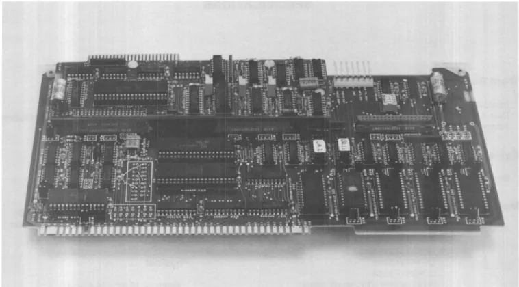
ZX-85
&
ZX-88 PROCESSOR BOARDS
• 8085A-2 or 8088 CPU
• 5 MHz Internal CPU Operation
• 64K BYTES of Dynamic RAM
• MUL TIBUS Compatible
• Two RS-232 Channels
• Boot/Monitor on a 2732A EPROM
• 8219 MUL TIBUS Arbitrator
• Two 8259A PIC's
• MDS IPB-80, IPC-85 Compatible
• Run Standard MDS DOS Software
• ZX-85 and ZX-200 Form a Minimal Development System •
This Zendex offering in two versions with different CPU's as the ZX-85 and ZX-88 Microcomputer Boards support various standard Disk Operating Systems (DOS). The ZX-85 uses the 8085AH-2 CPU for execution of 8-bit code (MDS compatible) while the ZX-88 uses the 8088 CPU for execution of 8086 code over the 8-bit system MUL TIBUS. The ZX-85/88 has an on-board complement of 64K BYTES of Dynamic RAM fully mapped into the first segment of the 1 M BYTE range. Also provided as part of the on-board memory is a 4K BYTE 2732A EPROM shadowed in for a 2K BYTE Boot and a 2K BYTE Monitor. The programs on the EPROM are in the appropriate code for either the 8085 or 8088. The boards include two serial 10 channels, three timers and two priority interrupt controllers. Each board presents two RS-232 interfaces to edge connectors opposite the MUL TIBUS edge.
Functional Description:
Changeover from one CPU type to the other is easily accomplished through the use of four row sockets pro-vided for the CPU chips. Other devices that must be re-moved, installed, or changed to complete the switchover have sockets installed.
The 8088 CPU version (ZX-88) has the circuitry installed to provide for the full 1 M BYTE addressing capability of the MUL TIBUS. Both CPU versions (ZX-85, ZX-88) have on-board clocking circuits to provide the 5 MHz maximum internal clocks.
The ZX-85/88 Processors are intended for use in a stan-dard SBC System and are therefore configured on 6.75" x 12.00" circuit cards. The ZX-85 may however be run in the IPB slot of a Series II MDS Chassis for an overall speed improvement. The ZX-85/88 do not implement the inter-rupt push-buttons and displays found on the Intel IPB boards and do not have the attendant extension to the front panel. The user may generate these interrupts directly on the MUL TIBUS with the appropriate switches mounted on this panel and associated logic. A Zendex ZX-903 may prove helpful in this regard. RS-232, lac and Pia interfa-ces are pinned alike with the IPB for connection at the auxilliary connector P2 that faces the MUL TIBUS. Oppo-site the MUL TIBUS are two 26-pin edge connectors for user serial RS-232 that repeat the serial lines at P2.
The on-board 64K BYTE RAM is implemented as 64K x 8 bits. A negative 5 volt regulator for the type 4116 RAMS uses the -12V source as a supply. An Intel 8202A Dynamic RAM Controller simplifies the DynamiC RAM use and it provides refresh and arbitration functions. The RAM Block resides on the MUL TIBUS as a slave unit and is available for all Bus-Masters.
The 2732A EPROM is organized into a bottom 2K BYTE Boot/Diagnostic and a top 2K BYTE Monitor program. A CPU control circuit in the 10 system enables the Boot/ Diagnostic portion at the reset address after system ini-tialization. Later execution of a control sequence will disable the Boot portion of EPROM addresses, and there-after RAM will exist at that location.
Two type 8259A Interrupt Controllers are used. One col-lects interrupts from on-board 10 sources and Pia and lac sources and then presents these to "INT 7" of the System Interrupt Controller. The system PIC has all of its inputs connected to the MUL TIBUS Interrupt System. One of three timers within an 8253 Timer provides a real time clock interrupt to the 10 PIC. The other two timers in the 8253 provide Serial Baud Rate Clocks to the 8251 A USART's.
The MUL TIBUS arbitration for the CPU is implemented with an Intel 8219 Controller. An on-board parallel priority network with input/output at P2 maps the ZX-85/88 as lowest master in the system. Eight request inputs and eight priority grant outputs are provided at P2 for the other masters in the system.
At connector P2 all the signals for the Pia (Parallel 10) and lac (10 Controller) are provided along with partially decoded controls. A separate lac board would provide interfaces to a built-in CRT, keyboard, and single diskette drive. A separate Pia board connected to P2 should pro-vide Serial RS-232 connectors, PROM Programmer, Line Printer, and TTY interface circuitry. Zendex makes a Pia board under model number ZX-904.
The user may select to use the two RS-232 interfaces at J1 and J3 directly. The functions for PROM programming and diskette systems may be implemented on the MUL TI-BUS with such products of Zendex as the ZX-908 Pro-grammer and ZX-710/720 Diskette System.
The Boot/Monitor program in the 2732A EPROM detects whether or not Zendex MUL TIBUS boards are installed for the PROM programming and diskette functions and will steer data accordingly. User serial 10 console detection is accomplished by typing a space bar at the terminal des-tined to be the console after reset. A reset switch is pro-vided on the ZX-85/88 for manual system initialization.
Compatible software for the ZX-85 includes Intel ISIS-II, and CP/M.
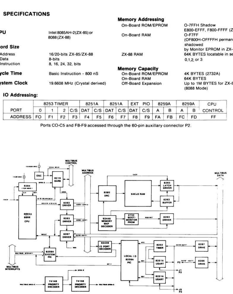
SPECIFICATIONS
CPU
Word Size
Address Data InstructionCycle Time
System Clock
10 Addressing:
InteI8085AH-2(ZX-85) or 8088 (ZX-88)
16/20-bits ZX-85/ZX-88 8-bits
8. 16. 24. 32. bits
Basic Instruction - 800 nS
19.6608 MHz (Crystal derived)
Memory Addressing
On-Board ROM/EPROMOn-Board RAM
ZX-88 RAM
Memory Capacity
On-Board ROM/EPROM On-Board RAMOff-Board Expansion
0-7FFH Shadow
E800-EFFF. F800-FFFF (ZX-85) O-F7FF
(OF800H-OFFFFH permanently shadowed
by Monitor EPROM in ZX-85) 64K BYTES locatable in segments
0.1.2. or 3
4K BYTES (2732A) 64K BYTES
Up to 1 M BYTES for ZX-88 (8088 Mode)
8253 TIMER 8251A I 8251A EXT Pia 8259A 8259A
I
CPUu,ca
PORT 0 1 2 CIS OAT CIS I OAT CIS DAT CIS A B A
I
B I ADDRESS Fa F1 F2 F3 F4 F5 I F6 F7 F8 F9 FA FB I FC ! FDPorts CO-C5 and F8-F9 accessed through the 60-pin auxiliary connector P2.
1
1!1 .•• ,8I11HZ CJ
88SSA SII88
CPU
1O,IIII.flD.Wfl .... S1
MULTBUS CONTROL
MULTBUS ADDRESS
8282
DRC 64Kx8 RAM
'====-===----'\1 825I1A r"---'-'--'--'----.--v1SYSTEM
PIC J 4 - - - '
74148 PRIORITY ENCOOER
Jr'".'
74138 PRIORITY OECODER' - - - - t - - J l P2
L - - - t - - J 3 P2
FIG. 2: ZX-85/88 PROCESSOR BLOCK DIAGRAM
CONTROL FF
MULTIBUS DATA
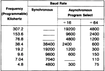
Serial Baud Rate
Baud Rate
Frequency ! Synchronous Asynchronous
(Programmable) Program Select
Kilohertz
+16
+64
307.2
- -
19200
4800
153.6
- -
9600
2400
76.8
- -
4800
1200
38.4
38400
2400
600
19.2
19200
1200
300
9
.
6
9600
600
150
7
.
04
7040
- -110
4.8
4800
300
75
Serial 10 Modes
Synchronous 5-8 bit characters with internal or exter-nal synch jumper selectable. Auto synch.
Asynchronous 5-8 bit characters, BRK generation, 1, 1 V2,
2 bit stop.
Interrupts Single level to RST 7 on 8259A master over MUL TIBUS from 8259A slave. 1.0. available from slave 8259A on-poll to detect which 8251A and T IR.
Optional Order Numbers
Kit-85 Changeover Kit to Convert ZX-88 to ZX-85
Kit-88 Kit to Change ZX-85 to ZX-88
Interfaces
MULTIBUS Serial 10 Interrupt
Memory Expansion
Physical
All signals TTL (P1-P2) RS232C to J 1, J3, P2 TTL Active Low, 8 levels J2., CPU Bus
Width - 12.00 inches (30.48 cm) Length - 6.75 inches (17.15 cm) Thickness - 0.50 inches (1.27 cm) Weight - 18 oz. (622.8 gm) MUL TIBUS Drive
Environmental
Power Requirements
+5V ±5% 2.25 Amps Typ. +12V ±5% 0.09 Amps Typ. -12V ±5% 0.01 Amps Typ.
(All include manual)
Ordering Information
Description
Tri-state TTL 32 ma sink
O°C to 55°C 5-95% R.H.
(no condensation)
Number
ZX-85 Processor Board with 8085AH-2 CPU and Monitor
ZX-88 Processor Board with 8088 CPU and Monitor
ZX-028B
128K BYTE RAM CARD
• 8/16 BIT DATA TRANSFERS
• BYTE SWAPPING LOGIC FOR
COMPATIBILITY WITH 8086 SYSTEMS
• MUL TIBUS COMPATIBLE
• SWITCH ENABLE OF ANY 32K
BLOCK IN 128K
• READ/WRITE DATA BUFFERS
• ON-BOARD HARDWARE REFRESH
CONTROLLER (8202A OR 8203)
The Zendex ZX-028 is a member of Zendex's line of Intel MUL TIBUS Compatible Products. The ZX-028 Board interfaces directly to any SBC-80 or SBC-86 Computer via the MUL TIBUS Interface. The RAM Card is available populated with 128K BYTES. READ/WRITE Buffers on each board buffer all data written into or read from the memory array. The ZX-028 responds to the full 20-bit address and will transfer either 8 or 16 bits parallel data automatically. The memory inhibit feature is implemented with the INH1/signal.
Interface
SPECIFICATIONS
Word Size - 8/16 bits
Memory Size OK, 32K, 64K, 96K, 128K Bytes Selectable by S1 Access Time - 414 nS (max)
Cycle Times
-Read Cycle - 489 nS mas Write Cycle - 489 nS max Refresh Cycle - 489 nS max Times measured with 24.0 MHz XTAL
Standard RAM Devices
All address, data, and control signals are MM 5290-3 National or TTL compatible and meet MUL TIBUS specifications.
BHEN/, ADROI, and INH11 Functions are fully implemented.
Address Selection
Switch selection for independent 32K byte blocks located in 128K Block. Switch location of 128K
Block in 1 M Range on 128K Boundaries. Full 20-Bit Addressing
Physical Characteristics
Width - 12.00 in. (30.48 cm) Height - 6.75 in. (17.15 cm) Depth - 0.50 in. (1.27 cm) Weight - 14 ounces (415 gm)
MK 4116-3 Mostek or Equal
Power Requirement
(Typ. fully loaded)+5 Volts ±5% @ 0.60 Amps +12 Volts ±5% @ 0.1 Amps -12 Volts ±5% @ 0.001 Amps
Ordering Information
Number
Description
ZX-200A SINGLE BOARD
DISKETTE CONTROLLER
• MEDIA COMPATIBLE INTEL SINGLEt
DOUBLE DENSITY FORMATS
• UPGRADE INTELLEC TO DOUBLE
DENSITY INTEL FORMAT
• DIRECT SHUGART SA801 INTERFACE
• PERFECT IN COMBINATION WITH ZX-85
FOR AN ECONOMY DEVELOPMENT
SYSTEM THAT'S INTEL COMPATIBLE
• REPLACES BOTH SBC-201
(PORT 88H) AND SBC-202 (PORT 78H)
• ISIS-II, RMX COMPATIBLE
• CONTINUE TO USE INTEL SINGLE
DENSITY LIBRARY ON HAND
• 5 VOLT ONLY POWER REQUIREMENT
• SECONDED SOURCED BOARD
PRODUCT
The Zendex ZX-200 Diskette Controller is a one board solution to running Intel's single and double density media on an Intellec MDS or SBC system. The hardware interface to the computer meets the Multibus specification and the software protocol required of the host allows use of unmodified ISIS-II disk operating software in the MDS or RMX software in SBe systems.
The FDD Interface is pinned alike with Shugart's SA800 Series and this allows the use of inexpensive ribbon connector systems. Up to four diskette drives may be operated over the single FDD Interface.
FIG. 1: ZX-20OA CONTROLLER BOARD
The ZX-200 supports up to four drives, single sided 8" only. All four drives will play double density format while the first two only will play the single density format. The selection, by the host CPU, of which drive is to respond in what density is con-trolled by the selection of logical device names. Use of FO, F1, F2 or F3 results in double density operation to physical drives 0, 1,2 and 3, respectively. By using logical device names, F4 and F5, the operation will be single density to physical drives 0 and 1, respectively.
The ZX-200 Controller maps into 10 Ports 78H-7FH and 88H-8FH. The disk operation descriptor is placed in a 7-10 byte block of host memory called the 10PB. The host then outputs the address of the 10PB to a pair of ports on the ZX-200. The ZX-200 then fetches the 10PB constructed by the host and performs the operation described in the 10PB. When the task is complete the ZX-200 can issue an interrupt to signal the host that the result information is available. Performing a port input by the host will return result information over the data bus. The ZX-200 appears to a Multibus system as an SBC-202 addressed at 78H (system) and an SBC-201 addressed at 88H (add-on).
The ZX-200 uses TTL random logic for FDD Interface and format control and 8085A CPU for control, a 2716 EPROM and an 8257 DMA Controller.
SPECIFICATIONS
Electrical
Power - 5 Volts @ 1.0 Amps (Typical) Transfer Rate - 250K, 500K
Data Bus - 8 Bit Parallel 10 Address - 8 Bit Parallel MEM Addressing - 16 Bit Parallel
Master Modes - Multibus Slave or Master
Connectors
Bus: 86 PIN @ 0.156" Centers (Multi bus) Disk: 50 PIN @ 0.1" Centers (SA800)
Documentation
ZX98-200 Hardware Reference Manual (Supplied), Includes Schematics Controller Firmware Source Code Listing, Installation Instructions and Descriptions
Physical
Height - 6.75 Inches Width - 12.00 Inches
Thickness - 0.50 Inches (Max)
Weight - 10 Ounces Net, 2 Pounds Shipping
Operating Temp - 0° to 50° C, 5 to 95% R.H.
Ordering Information
Number ZX-200A
Description
ZX·204 ECONOMICAL
DISKETTE CONTROLLER
• Single and Double Density
IBM Formats
• 5 Volt only Operation
• Direct Memory Access Controller
• Standard and Mini FDD Interfaces
• Bus Arbitrator for Master
Mode Operation
• Digital Data Separator
• Write Precompensation
• MUL TIBUS Compatible
• Memory-to-Memory Block
Move Latch
• Recommended for 5.25"
Mini-Floppy Use
The ZX-204 is intended for use by the OEM systems designer who requires the maximum in speed and efficiency and a minimum of hardware costs in a Diskette Controller. The ZX-204 includes an integrated Floppy Disk Controller (FDC) chip, DMA Controller, Digital Data Separators, MUL TIBUS Arbitration Logic, Standard and Mini FDD Interface, and MUL TIBUS Interface circuits all on a standard size card that requires 5 Volts only.
The disk operation is set-up and described by 10 Channel Commands and data transfers are carried out by a Direct Mem-ory Access (DMA) Controller. The operation when complete is signaled by interrupt and the results are obtainable by further 10 Channel Command executions.
FIG. 1: ZX-204 CONTROLLER
The ZX-204 interfaces with most Standard and Mini-sized FDD's due to the programmable timing and hardware jumpers provided. Both sizes of drives are supported by individual 50 in and 34 pin card edge connector interfaces.
I BM Formats are used for soft sectored operation. Large, non-I BM, sector sizes may also be used due to the programmable specification available in the FDC.
The composite read data from the FDD is transferred through a digital data separator that requires no adjustment. Write data is precompensated by the FDC by 125 nSec early, late, or zero.
Fifteen FDC command types provide for full control of data transfer types and specification and include high speed disk to memory comparison scan commands. The disk can be scanned for comparison of one sector to a whole cylinder's worth of data to memory data.
A large blank area is left on the board for art work overlays by Zendex for customization. This area could contain a 16K x 8 Bit RAM, or a CPU and RS232 Channel.
SPECIFICATIONS
Electrical
Power - 5 Volts @ 1.0 Amps (typical) Transfer Rate - 500K Bits/Second maximum Data Bus - 8 bits parallel, Address - 16 bits
10 Addressing - 0-14H or 80H -94H jumper selectable Interrupts - one of eight, selectable
Documentation
ZX98-204 Hardware Reference manual for ZX-204 Diskette Controller
Components Used
FDC - NEC 765 or Intel 8272 DMA - Intel 8257-5
Bus Arbitration - Intel 8219
Data Separator - DisCTete Digital Type
Maximum Configurations
Four double or single sided, double or single density 8" Drives
Three double or single sided, double or single density 5.25" mini-drives
Physical
Height - 6.75 inches Width - 12.00 inches
Thickness - 0.50 inches (max.)
Weight - 10 ounces net, 2 pounds shipping
Operating Temp. - 0° C to 50° C, 5 to 95% R.H. no condensation or frost
Connectors
Bus: 86 pin @ .156" (MUL TIBUS) Disk: 34 pin @ .1" (SA800/801 pin)
34 pin @ .1" (SA400/450 pin)
Ordering Information
Number ZX-204
Description
ZX-20SA FLEXIBLE
DISKETTE CONTROLLER
• ALTERNATE TO INTEL SBC-208
• SUPERIOR DATA RECOVERY
CIRCUITRY FOR DOUBLE DENSITY
RELIABILITY
• MULTI-SECTOR, MULTI-TRACK DATA
OPERATIONS WITH DMA CAPABILITIES
• FEATURES POWERFUL
NEC uPD 765A CHIP
• PHASE LOCK LOOP DATA
SEPARATOR HAS WIDE EFFECTIVE
MARGIN
• MAJOR SOFTWARE SUPPORT
FOUND IN INTEL DRIVERS
COMPATIBLE TO ZX-208A
The Zendex ZX-20BA Flexible Diskette Controller will support a wide range of soft sectored dual density drives. Up to four standard or mini drives may be accommodated by a single ZX-20BA. The IBM System 34 and 3740 Data Recording Formats are handled by the ZX-20BA. The user can elect to use the ZX-20BA in either polled or interrupt mode and in either DMA or Non-DMA mode. A single SBX-Module connector is provided for incremental 10 expansion of the user's system.
FIG. 1: ZX-20BA
SPECIFICATIONS
Com pati bility
CPU - Any Multibus SBC Board System
Devices - Single or Double Density Diskette Drives Single or Double Sided. Standard or Mini-size Compatible Drives include:
STANDARD (8") MINI (5)4")
Memorex 500.550 Shugart 400.450.460,410 MFE 700. 500 Series Pertee 250,200
Shugart 800.801,850.851 Siemens 200-5. 100-5
Physical
Environmental
Width - 6.75 Inches (17.15 cm) Height - 0.5 Inches (1.27 cm) Length - 12.0 Inches (30.5 cm) Shipping Weight - 2 Pounds
Electrical
Power Requirement - +5 VDC @ 2.5 A (Typ) -5 VDC @ 20 rnA (Typ)
Temp - 0° to 55° C (Operating) - 55C to 85° C (Storage) Humidity - Up to j90% R.H. Without Condensation
Ordering Information
Number
ZX-208A
Description Diskette Controller (Includes Manual)
7ende"xff
ZX-609 MUL TIBUSTM 9-SLOT CARDCAGE
• High Performance Versatile
MUL TIBUS™ Backplane and
Cardcase Unit
• On-board Parallel Priority Network
Resolves MUL TIBUSTM Master Access
Contention for Bus Exchanges
• Building-block for Economy
Development System -
Runs Leftover
Spare Intel IPB-80 CPU or ZX-85
• 9-Slot Capacity Compatible With
MUL TIBUSTM SBC Board Products
Fits Standard 7-inch High System
Chassis, Table-top Enclosures and
RETMA Racks
• Clean Short Bus Wiring Geometry for
Low Capacitive Loading and Immunity
to Noise
• Supercedes Combination Intel
SBC-604/614 Paired Modular 8-slot
Cardcages
The ZX-609 cardcage single unit provides housing for 9 MUL TISUS'· sized boards. Stand-alone ZX-609 is complete with bus signal termination circuits and power supply connectors. The unit may be packaged in a 7-inch high enclosure.
The unique innovation in the ZX-609 backplane consists of two sockets wired into the MUL TISUS'· to provide parallel technique, priority bus resolution using 74138/74148 DECODER/ENCODER TTL integrated circuit chips. These are re-moved whenever a ZX-85/88 or other SSC card is present with parallel priority resolution implemented on-board the SSC card. Serial (fixed) priority assignment schemes are effectively limited to three bus masters before the propagation delays become troublesome. The chips of the network resolver on the backplane are removed when serial techniques are em-ployed. On-bus resolution circuitry simplifies and expands the utility of having many multi masters simultaneously on the bus.
Auxiliary connectors are provided on the backplane printed circuit board at the bottom of the cardcage. 50 lines on J11
provide for a parallel 10 processor (ZX-904) capability for using CRT, line printer, TTY and UPP devices. Eight interrupt
lines and reset on J12 provide for operator control via a control panel (ZX-903). DC power on J17 is designed to serve the
parallel 10 processor function.
BREQ/s
TOP 8 SLOTS (REQUEST)
74148
PRIORITY ENCODER
9TH SLOT BPRN/O (GRANT)
74138
PRIORITY
-DECODER
MULTIBUS BPRN/s
TOP 8 SLOTS (GRANT)
ZX-609 CARDCAGE BACKPLANE
MUL TIBUS PARALLEL PRIORITY RESOLUTION NETWORK
Connectors Supplied on Backplane
Pia on J11, ANSLEY 609 - 5022 MR INT/RESET on J12, ANSLEY 609 - 2622 MR DC Power on J17, MOLEX 09 - 66-1071
(GND, -10V, -12V, +5V, GND)
Ordering Information
Part Number Description
ZX-6098 Cardcage. Includes
backplane schematic drawing.
Optional Accessories
74148174138 TTL integrated circuits, (2 chips to fit Augat 516-AG110 sockets) Cable assemblies for connectors J11 and J12 ZX-903 Interrupt Board
ZX-904 Parallel 10 Module ZX-640 Power Supply
Zende,x"
'
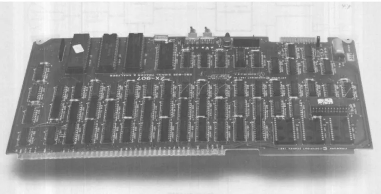
ZX-907 BUS TRACER
• 40-BIT WIDE TRACE
• 1024 BUS CYCLES STORAGE
IN ON-BOARD RAM
• ON-BOARD 808SA-2 PROCESSOR
• ADDITIONAL ON-BOARD PROM
SPACE FOR PROGRAM EXPANSION
• COMPARA'TOR EXTERNAL OR CRT
CONTROLLED ARM AND BREAK
FUNCTIONS
• CRT DISPLAY AND CONTROL
• BREAKPOINT CAN BE SET
ON ADDRESS
+,
<
,
>
• 8 OR 16 BIT PROCESSOR
COMPATIBILITY
• USER FRIENDLY PROMPTING
• LIKE THE ZX-906 BUT PROVIDES
TRACE DATA
The ZX-90? is a single board Multibus module which can trace up to 1024 bus events priorto a presetable breakpoint. Each
event is determined by monitoring 20 address, 16 data, and 4 control bits. An interpretation is then made as to the action,
memory or I/O location and data for each event. The interpreted events are then displayed on a CRT. In addition, the CRT
provides control for all trace functions through software prompts. ARM and RESET switches are located on the PC board. An on-board 8085A-2 processor provides intelligence for all functions and PROM sockets are available for up to 16K of user program and enhancements.
FIG. 1: ZX-907 BUS TRACER
Power Consumption
+5V @ 1.7 Amp -12V @ .015 Amp +12C @ .015 Amp
Bus Capture Speed
Less than 350 nanoseconds
Operating Temperature
Physical
Width - 12 inches Length - 6.25 inches Thickness - 0.5 inch Weight - 12 ounces
'---- L-...,
• CONTROL
TRACE ADDRESS SEQUENCER
...--_'..:..' .::...0'..:..",,---,11 40 8 IT LA TC H
:10 ADDRESS
L!!!..,.
40 lIT x 1 K TRACE MEIIORY
24 liT COMPARATOR
< - >
I I I
SELECT
1
TRACE L - - - f FLIP-flOP
TPI
EXT.BREAK
TRACE
I-22 OUTPUT
. . K
AUX. PROM
2 OUTPUT
875. 2K PIIOII
BLOCK DIAGRAM
FIG. 2
CPU
Intel 8085A-2
System Clock
6.144 MHz
Interface
The ZX-907 can be installed in any slot in the Multibus. It is a passive listener and never can take control of the bus.
Memory
2K RAM
2K PROM
PROM expandable to 18K in 4K increments 40X1K trace
, . - - 2K RAM
Type
2114 Static and 8155 8755
2732A 2114-3 static
I--_~J
PRINTER1
-I
(OPTIONAL)ON BOARD
8085.-2
~
8251USARTRSERS
1 ____ & AS232 lA1
'--.,... ... .,....1 DRIYERS TERMINAL
t
BAUD
L-_-I GENERATOR
Zende;><~
'
ZX·660A SYSTEM CHASSIS
• Replacement for Intel SBC-660
• ±5 ±12 Volt Power Supply with
30 AMP 5 Volt
• Painted Sky Blue for Attractive
System
• 110/220V. 50160
Hz Operation
• 9-Slot Cardcase/Backplane
• Whisper Quiet Fans
• 19-inch Rack Mountable Chassis
• Pop-off Front, Top and Back Panels
• Hinged Front Panel for Easy Access
The ZX-660 System Chassis is an attractive seven-inch high chassis designed for use with Multibus compatible boards. The Chassis is finished painted sky blue and comes with rubber feet and features quiet muffin fans for use on a tabl.e top in an office environment. The ZX-660 is intended to be a more reasonably priced and configured chassis and is offered as a
direct substitute to the Intel SBC-660.
The Cardcase and Power Supply may be reversed within the Chassis on the unique double-drilled bottom plate so the Multibus cards may be withdrawn through the front access. This feature can be important in testing a "racked" system. The front dress plate pops off and the control panel is hinged along the bottom and has magnetic keepers to hold the panel closed.
FIG. 1: ZX-660A CHASSIS
FIG. 2: Two ZX-660A CHASSIS' shown here with cardcase/power supply reversed in one. Top and front pop-off's removed for clarity.
SPECIFICATIONS
Electrical
Input Power Fusing - Circuit Breaker in Switch Frequency - 50/60 Hz ±5%
Voltage - 115V/230 VAC ±10% Output Power:
Power +12V
+5V -5V -12V
Output Current 4.5A
30A 1.75A 1.75A Remote Sensing - Provided for +5 VDC Output
Output Ripple and Noise - 10 mV P-P max (DC-500khz)
Limit 5.4A 3.6A 2.1A 2.1A
Output Transient Response - No More Than 50mS for ±50% Load Change Power Fail Detection - TTL Open Collector Signal Provided When Input Voltage
Drops below 90% of Nominal. DC Voltages Remain Within 5% of Nominal for 3.0 mS After AC Low Goes True.
Over-Volt 15V ±1V 6.2V ±O.4V -S.2V ±O.4V -.15V ±1V
Equipment Supplied
Ordering Information
ZX-6S0 Chassis with ZX-S40 Power Supply ZX-609 Cardcase/Backplane, Quad Fans, Pop-Off
Covers, AC Cord, ZX-903 Interrupt/Reset Control Panel. ZX-660 Manual with Schematics, Parts Lists & Assembly
Drawings.
Part ZX-SSOA
Description
7ende;x'·'
ZX-655A SYSTEM CHASSIS
• Direct Replacement for Intel SBC-655
• Quad Linear Power Supply
• 110 Vac/220 Vac 50/60 Hz Operation
• 4-Slot Cardcase
• 4 Whisper Fans for Quiet Operation
• Cards Can Be Removed Through
Front or Rear
The Zendex ZX-6SSA chassis is an attractive 3.S" tall four-slot system box suitable for office use. The all-steel construction allows double duty in an industrial situation like 19" RETMA racks. This product features Zendex's unique innovation of double drilling the bottom plate so cardcase and power supply may be reversed by the user for cards-front or cards-rear configuration.
The linear quad supply is the ZX-63S (see data sheet) and it will power up to 14.0 AMPS on the +SV line. Each chassis is painted a rich blue (like IBM typewriters) and comes with rubber feet to protect table top surfaces.
FIG. 1: ZX-655A 4 SLOT CHASSIS
7ende,><~
ZX·705A
DISKETTE HARDWARE $YSTEM
• Two Shugart SA801 R Drives
• 19" Rack Mountable Chassis
• Includes Zendex ZX-204 Diskette
Controller
• Complete with Cables and Cord
The ZX-705 is a complete diskette subsystem that includes the ZX-730 Dual Drive Chassis and ZX-204 Controller. The drive chassis is provided in a 16-gauge steel cabinet painted sky blue and comes with provision for slides for use in a 19" Retma rack.
The ZX-204 Controller is capable of running up to four double-sided, double density drive units. Selection of disk side, density and unit are completely under software control of the ZX-204. The Controller features an NEC 765 FDC, and 8257 DMA Controller and an 8219 Multibus Arbitration Unit.
ZX-705 DISKETTE HARDWARE SYSTEM shown with optional software
ZX-710/720 MOD 200 DISKETTE
HARDWARE SYSTEM
• Full compatibility with Intel SeC-80 and
MDS Multibus computers
• Direct replacement for Intel
MDS-710
&
MDS-720
• Controls up to four double density drives
• Two Shugart SA 801 drives provided in
rack mountable chassis/cabinet
• Software support is provided in ISIS,
RMS/80 and CP/M compatibility
• Data transfers performed through DMA
operations
• Emulator firmware in EPROM
• Single +5VDC supply for FDC
• Uses ZX-200A Controller
The Zendex ZX-71 01720 Diskette Hardware System is an intelligent, high-speed, random access bulk storage system for use in
Intel compatible SBC-80, System 80, and Intellec Series I and II Computers. The ZX-710/720 is a single replacement model for the MDS-71 0 and MDS-720 Systems offered by Intel. The single controller board simply plugs into any MULTI BUS type back-plane.
FIG. 1: ZX-7101720 DISKETTE HARDWARE SYSTEM
Functional Description
The ZX-710/720 Diskette System provides selectable
single density (FM) and double density (MMFM) access to bulk storage on floppy diskettes. The controller hard-ware will allow up to 4 double sided drives to be used, thus providing up to 4 million bytes of data storage. The con-troller is implemented with the industry standard 8085A CPU and the versatile 8257 DMAC. The controller (avail-able separately as the ZX-200) provides an interface to the two Shugart SA801 Floppy Disk Drives (FDD) in the ZX-730 Chassis. The diskette system can record all data in Intel compatible soft-sector formats.
Controller Board
The Floppy disk Controller (FDC) is capable of controlling up to four 8" standard Disk Drives. The ZX-71 0/720 or just the ZX-200 FDC and your drives, can be paired with any compatible single-board computer to make a very power-ful two-board, floppy disk based computer system. With on-board CPU, Firmware, RAM, and all necessary Direct Memory Access Control (DMAC), the ZX-200 is a complete interface between the ZX-730 Drives and any MUL TIBUS Single Board Computer System. The ZX-7101
720 can also serve as a direct replacement for bulk storage systems in MDS-800, and Series II Development Systems.
The standard 201/202 Emulator Firmware allows the
ZX-710/720 to replace the following Intel Controllersl
Systems:
Single Density
SBC-201
SBC-211/212
MDS-2DS MDS-710
Double Density
SBC-202 MDS-DDS MDS-720
·Selection of single or double density operating modes
is made with unit selection via software. See ZX-200 Data
Sheet.
Programming Capability
IOPB Purpose - all diskette operatfons are initiated with simple 10 commands. Once started the FDC carries on the specified function without further intervention on the part of the Host CPU. There are only three steps required of the Host CPU to complete any diskette operation:
1. The Host must prepare an 10 Parameter Block (lOPB) in memory accessible by the FDC (shared main memory).
2. The Host then passes the address of the 10PB to the FDC with 10 output commands.
3. The Host must process the results of the opera-tion available with 10 input commands.
IOPB Format - The Host CPU solely prepares the 10PB, as any block of data in memory would be prepared, fol-lowing the format below:
BYTE DESCRIPTION
1 Channel Word
2 Diskette Instruction'
3 Number of Records
4 Track Address
5 Sector Address
6 Buffer Address (lower) 7 Buffer Address (upper)
8 Block Number"
9 Next IOPB ADR (Iower)" 10 Next IOPB ADR (upper)*'
*The eight available instructions with 201/202 Emulator Firmware are:
BYTE 2 BITS 0-2
0 No Operation
1 Seek
2 Format
3 Recalibrate
4 Read Data
5 VerifyCRC
6 Write Data
7 Write Deleted Data
**201 Mode only. Required to perform linked 10PB's.
Channel Commands - the 10 Channel Commands pro-vide the FDC with the method of assigning physical sec-tor numbering during format, ENABLE/DISABLE inter-rupts, and provide FDC operation results to the Host CPU.
General Hardware
The ZX-7101720 FDC automatically polls all drive ready lines between operations. The FDC's CPU notifies the Host CPU (by interrupt) whenever a drive has gone from ready to not ready (and vice versa).
Hardware Specifications
(Floppy Disk Controller Card ZX-200)
MEDIA
• FLEXIBLE DISKETTE, 8" STANDARD • ONE SURFACE PER DISKETTE • 77 TRACKS PER SURFACE (8")
• 128 BYTES PER SECTOR SINGLE DENSITY AND DOUBLE DENSITY
Physical Characteristics
MOUNTING - occupies one chassis card slot
HEIGHT - 6.75 in. (171.5 mm)
DEPTH - 0.5 in. (12.7 mm)
WIDTH - 12.00 in. (304.8 mm)
WEIGHT - 14 ounces
Drives
The ZX-200 directly interfaces with the following drives. Other type may require modification or additional inter-face circuitry and/or software.
MANUFACTURER 8" FLOPPY DRIVES
BASF
-Caldisk 143M
Memorex 550/552
Micropolis
-Persci 70,720,288
Pertec FD5x4, FD650
Qume Datatrak-8
Siemens FDD 200-8, 100-8
Shugart Assoc. SA800, 801
Specifications
ACCESS TIME
Rotational Speed - 360 rpm Average Latency - 83 ms Recording Mode - FM/MMFM Track-to-Track - 8 ms Head Settling Time - 8 ms Head Load Time - 35 ms
CHASSIS AND DRIVES
MOUNTING - Table-top or standard 19 in. RETMA cabinet
HEIGHT - 7.25 in. DEPTH - 20.3 in.
Electrical Characteristics
CONTROLLER
DC Power Requirements: 5V @ 3.0A Typ.
CHASSIS
AC Power Requirements: 3-wire input with center conductor (earth ground) tied to chassis
Single Phase: 115/230V AC; 50-60Hz; 160W
Environmental Characteristics
MEDIA
TEMPERATURE - 15.6°C to 51.7°C operating 5° C to 55° C non-operating HUMIDITY - 8% to 80% (wet bulb 29.4°C) operating
8% to 90% non-operati ng
CONTROLLER BOARD
TEMPERATURE - O°C to 55°C non-operating -55° C to 85° C non-operating HUMIDITY - Up to 90% relative humidity without
con-densation, operating; all conditions with-out condensation of water or frost, non-operating
CHASSIS AND DRIVES
TEMPERATURE - 10°C to 38°C operating
-35° C to 65° C non-operating
HUMIDITY - 20% to 90% (wet bulb 26.7°C) operatin 5% to 95% non-operating
Material Supplied
ZX-7101720 DISKETTE HARDWARE SYSTEM USERS MANUAL
ZX-200A HARDWARE REFERENCE MANUAL
Schematics and Hardware descriptions
ZX-730 TWO DRIVE CHASSIS & CABLES
ZX-200A CONTROLLER with 201/202
Emulator Firmware
Ordering Information
Part No. ZX-710720 MOD 200
Description
Zende/<~
ZX-740WC
10M FIXED, 10M REMOVABLE HARD DISK SYSTEM
• SA1004 10M BYTE WINCHESTER
DISK DRIVE
• DTC-900 CONTROLLER (OR EaUAL)
• STEEL, RACK-MOUNT CABINET,
PAINTED SKY-BLUE
• DATA PERIPHERALS LYNX DRIVE
• CONDOR FNBB-120W POWER SUPPLY
• DTC-86 MUL TIBUS INTERFACE UNIT
INCLUDED
The Zendex ZX-740WC is the "together" solution for the OEM who has selected the Shugart equipment for his use and
requires it pre-packaged, ready to use. Zendex assembles and tests the drives and controller in its heavy-duty steel chassis
and completes all wiring between. The host adaptor interface from the controller is brought out on an 8-foot ribbon cable
terminated with a 50-pin edge connector. This connector then installs on the DTC MUL TIBUS interface. CP/M-80 and CP/M-86 CBIOS for ZX-740WC are available. The ZX-740WC elegantly solves the backing up problem to 10M Byte fixed Winchester.
FIG. 1: ZX-740WC
MODEL 805
MICROCOMPUTER DEVELOPMENT SYSTEM
• Same as Model 835 Less an IPB CPU
Card. See Model 835 Data Sheet for
Complete Specs
• Easily Upgradable to MCS-86 Family
With 8088 Based ZX-88 Board
• Series II Type Rear-Panel Interfaces to
CRT, Line Printer, TTY and UPP. Optional
PROM Programmer Sockets With CP/M
&
ISIS-II Utilities on Diskette Are Available
• Adds an Extra Complete Development
System at a Small Fraction of the
Replacement Cost -
Uses Standard
CRT Terminal
• Dual FD Drive System 1 MB Bulkstore
in Its Own Cabinet
• Diskette Controller Operates Up To 4
Drives Over One MUL TIBUS Interface
Card
• Supports 8- and 16-Bit SBC Products
in a 9-slot Cardcage With a Unique
MUL TIBUS Backplane
• Runs Various Design Aids and
Diagnostic Tools, MULTIBUS Display,
Tracer Analyzer and Assorted ICES,
Among Others
Presents an ideal solution to the "left-over" IPS-80 CPU card and 32K byte RAM card when an Intellec Series-II has been upgraded using MDS-505, -556 or Series III to displace the originallntellec cards. Simply plug in the spare Intellec cards to work with the extra system that is fully ISIS-II double density compatible. Model 805 is immediately upgradable to Zendex Models 835 and 845 using Zendex add-ins and add-ons.
MODEL 835
MICROCOMPUTER DEVELOPMENT SYSTEM
• Complete Microcomputer Development
System Support for MCS-80 and
-85 Families
• Upgradable Easily to Support MCS-86
Family With an 8088 Chip Changeover
(KIT-88)
• 5 MHz Internal CPU Operation (8085AH-2)
64K Byte RAM Memory With Boot/
Monitor in 4K Byte EPROM Memory
On-board CPU Card
• MUL TIBUS Standard Interface With a
Unique and Versatile 9-slot Cardcage
Backplane ZX-609
• MDS-800 Type Interfaces to CRT, Line
Printer, TTY and UPP Universal PROM
Programmer
• Dual Floppy Disk Drive System, 1 MB
Bulk Store -
Stacking Cabinet for Table
Top Use or Rack Mounting
• Diskette Controller Operates up to Four
Drives Over One MUL TIBUS Interface
Card, Compatibly With ISIS-II and CP/M
Operating Systems
• Runs Compatible Design Aids and
Diagnostic Tools: MUL TIBUS Display
Card (ZX-906), Tracer Analyzer (ZX-907)
and Various In-circuit emulators and
Prototyping Cards.
• Supports 8 and 16-bit SBC Products
Available From 30 or More
Plug-Compatible Manufacturers Building to
the MUL TIBUS Standard
• Uses Intel 8085AH-2 CPU Chip for
Software License Compatibility.
Zendex Model 835 is a complete microcomputer development system, hardware and software compatible with Intel's Intellec Series II MDS models. Model 835 principally serves as a center to develop microcomputer-based products. The plug-compatible-manufacture hardware and software may be used interchangeably with Intellec's, particularly Models MDS-230 and -235, in expanding and upgrading systems in the field. Model 835 includes an integrated processor board, Zendex ZX-85 with a 10 MHz 8085AH-2 CPU, 64K byte RAM, 4k byte EPROM, two 8251A USARTs with RS232 compatible serial I/O ports and two 8259A interrupt controllers. The next electronics card in the 9-slot cardcage is a ZX-200 diskette drive controller, working in either FM/MMFM, single or double density Intel format; allowing software media to be exchanged with Intel for complete support. The electronics baseboards are housed in a unique ZX-609 MUL TIBUS backplane and 9-slot chassis. The operator interrupt and reset control panel, ZX-903, is located on the front apron. Parallel 10 interfaces for a CRT, line printer, TTY and UPP (universal PROM programmer) are mounted on the ZX-904 printed circuit board rear panel. Pop-off front, top and back panels provide easy access. Withdrawal of cards from the front has been facilitated with predrilled holes in the chassis, for reversing positions of power supply and cardcage, important when testing a rack-mounted system.
The dual, horizontally mounted, single or double density diskette drives are housed in a separate matching, stackable cabinet. One controller interfaces with up to four floppy disk drive units. Floppy disk drives and various hard disk system (10MB) options may be added in separate cabinets.
Industry standard MP/M V2.2 diskette-based operating system performs dynamic file management and fast assembly of user programs. It has many of the features and utilities found in Intellec ISIS-II DOS. Zendex provides a file transferring capability back and forth between CP/M and ISIS II. Breadth of compatible support based on CP/M includes, PLl1-80, LlNK-80, PASCAL and FORTRAN higher level languages offered by Digital Research and other independent suppliers (extensive list available). Replete with software, development aids and diagnostic tools, the 835 development system is all that is required for assembling and/or compiling and debugging software and hardware for 8080/8085 microprocessor-based products. Zendex building-block system components and subsystems offer a complete range of mix and match microcomputer innovations in total systems, individual board products and in upgrading enhancements for existing MDS model development stations.
32K AUX ROM
BOARD
8741A (UP'-<tlA)
FIG. 2: MODEL 835 BLOCK DIAGRAM
8085A-2 CPU
FUNCTIONAL DESCRIPTION
Hardware ComponentsThe Zendex Model 835, housed in two untis, is an extremely versatile, plug-compatible-manufacture, microcomputer development system. The first cabinet houses a high per-formance, multi-purpose, MUL TIBUS backplane card and chassis, with a 9-slot cardcage, power supply, fans, cables and holding three SBC-type and two auxiliary, panel mounted, printed circuit boards. Cards may be withdrawn from the front. A separate, matching and stackable chas-sis (with rubber feet included for table-top use) also allows easy, optional rack mounting, with predrilled holes for rack slides and all-around accessibility. This second cabinet houses the floppy. disk subsystem. (Note, a ZX-200 single board diskette controller card is included in the first cabinet). Shugart SA-801 standard floppy disk drives, power supply and cables for connection to the main chas-sis, are included in the second cabinet. A block diagram of Model 835 is shown in Figure 2.
CPU Card - The Master host CPU card (ZX-85), inte-grated processor board (IPB), contains its own advanced, high performance microprocessor, mem