FOR
WINDOWS®
USERS GUIDE
OrCAD Capture® for Windows®
User's Guide
This manual provides step-by-step process
descriptions that explain how to use DrCAD
Capture for Windows. Reference information is in
the online help. Placing reference information in
the online help makes it possiblefor DrCAD to
provide complete and up-to-date information to
you. In addition, information is easier to find in the
online help because of its search capabilities.
Use this manual as a tool to help you become
familiar with DrCAD Capture for Windows. As you
Copyright © 1997 OrCAD, Inc. All rights reserved.
OrCAD, OrCAD Capture, OrCAD Design Desktop, OrCAD Layout, and OrCAD Simulate are registered trademarks, and OrCAD Express, SmartDrag, SmartPlace, SmartRoute, and SmartWire are trademarks of OrCAD,Inc.
Microsoft, Visual Basic, Windows, Windows NT, and other names of Microsoft products referenced herein are trademarks or registered trademarks of Microsoft Corporation.
TrueType is a registered trademark of Apple Computer, Inc. PostScript is a registered trademark of Adobe Systems, Inc.
All other brand and product names mentioned herein are used for identification purposes only, and are trademarks or registered trademarks of their respective holders.
MN-01-5090
Third Edition 9 June 97
Technical support Corporate offices Fax
General email
Technical support email Web site
(503) 671-9400 (503) 671-9500 (503) 671-9501 [email protected] [email protected] www.orcad.com
Contents
About this manual... ix
Before you begin... ... ... ... ... IX Symbols and conventions ... ,... IX
Part One
Capture basics
Chapter 1
Getting started ... 3
Starting Capture ... ... ... ... ... ... 3
The Capture session frame... 3
Chapter 2
The Capture work environment... 5
The project manager .. ... ... ... 5
The browse window. ... ... ... 13
The schematic page editor... 14
The part editor ... 15
The text editor ... ... ... 16
The session log .... ... 17
The toolbar ... 18
The tool palettes ... 20
The status bar ... 23
Using help and the online tutorial.. ... 24
Using the Accessories menu ... 24
Selecting and deselecting objects ... '" ... ... 25
Grouping objects ... 26
Editing objects ... 27
Undoing, redoing, and repeating an action ... ... ... 30
Contents
Chapter 3
Starting a project ... 33
Creating new designs, libraries, and VHDL files ... 33
Opening files ... 35
Working with files in a project ... 36
Saving projects, designs, and libraries ... 37
Closing a project ... 38
Chapter 4
Setting up your project ... 39
Defining your preferences ... 40
Setting up your project template ... 49
Changing properties of existing projects ... 58
Changing properties of existing schematic pages ... ... ... ... 61
Chapter 5
Printing and plotting ... 63
Configuring a printer or plotter ... 63
Printing or plotting schematic pages ... 64
Printing or plotting parts or packages ... ... 64
Printing or plotting text editor windows ... ... 65
Previewing printer or plotter output.. ... ... 65
Scaling printer or plotter output... ... ... ... ... 66
Special considerations for plotting ... 67
Part Two
Creating deSigns
Chapter 6
Design structure ... 71
Flat designs... 72
Hierarchical designs ... 73
Connecting schematic folders and schematic pages ... 76
An example: creating a simple hierarchy... ... ... ... 78
Chapter 7
Placing, editing, and connecting parts and electrical'
symbols ... 81
Placing and editing parts... 82
Placing and editing power and ground symbols ... ... 89
Placing and editing no-connect symbols... ... 93
Placing and editing hierarchical blocks ... ... ... 94
Placing and editing hierarchical ports and hierarchical pins... ... 99
Placing and editing off-page connectors ... 104
Placing and connecting wires and buses ... 108
Contents
Chapter 8
Adding and editing graphics and text ... 115
Drawing tools ... 115
Drawing lines ... 116
Drawing rectangles and squares ... 1 1 7 Drawing circles and ellipses ... 118
Drawing arcs ... 11 9 Drawing poly lines and polygons ... 120
Adding fill to an object ... 121
Mirroring an object ... 121
Rotating an object ... 121
Cutting an object ... 121
Copying an object ... : ... 121
Pasting an object ... 122
Deleting an object ... 122
Placing a bitmap ... 123
Placing text ... 124
Chapter 9
Using macros ... 131
Recording a macro ... 132
Playing a macro ... 132
Configuring a macro ... 133
Naming a macro ... 135
Assigning a shortcut key to a macro ... 137
About the Capture to Layout macros ... 138
Chapter 10
Changing your view of a schematic page ... 139
Zooming ... 139
Moving to a new location ... 142
Displaying the grid and grid references ... 145
Finding parts in a project ... 145
Contents
Part Three
Libraries and parts
Chapter 11
About libraries and parts ... 149
Libraries ... 149
Parts ... 151
The design cache ... 152
Primitive and nonprimitive parts ... : ... 154
Chapter 12
Creating and editing parts ... 155
Creating a new part ... 156
About power and ground ·pins ... 168
Editing an existing part ... 170
Viewing parts in a package ... 172
Editing parts in a package ... 173
Viewing a part's convert ... 173
Part Four
Processing your design
Chapter 13
About the processing tools ... 177
Tools overview ... 178
Chapter 14
Preparing to create a netlist ... 179
Updating part references ... 179
Updating properties ... 183
Checking for design rules violations ... 186
Swapping gates and swapping pins ... 194
Chapter 15
Creating a netlist ... 197
Using the Create Netlist tooL ... 197
N etlist format files ... 199
Netname resolution ... 200
Creating a netlist for use with OrCAD Simulate for Windows ... 201
Chapter 16
Creating reports ... 203
Creating a bill of materials ... 203
Creating a cross reference report ... 206
Chapter 17
Exporting and importing schematic data ... 207
Exporting and importing designs ... 207 Exporting and importing properties ... 21 0
Contents
Chapter 18
Using Capture with OrCAD Layout for Windows ... 215
Preparing your Capture design for use with Layout ... 217
Creating a netlist for use in Layout.. ... 225
Loading a new netlist into Layout ... 226
Back annotating board information from Layout ... 226
Forward annotating schematic data to Layout ... 228
Cross probing between Capture and Layout.. ... 229
Chapter 19
Using Capture with OrCAD Simulate for Windows ... 233
Analyzing your Capture project with Simulate ... 233
Viewing signal values in Capture using intertool communication ... 235
Selecting signal sets in Capture for use in Simulate ... 236
Incorporating Capture netlist changes into a Simulate proj ect ... 238
Glossary ... 239
Index ... 247
About this manual
The OrCAD Capture for Windows User's Guide contains the procedures you need to work with Capture. To help you learn and use Capture efficiently, this manual is organized by tasks, beginning with the most common schematic design tasks (parts one and two), and moving on to more advanced
CMRlJN ! ::::'
Capture features (parts three and four). Many of the procedures described in this manual are also covered in the online tutorial, Learning Capture.
_Iclxl
Before you begin
Before you can use Capture, you must install Microsoft Windows on your computer, then install Capture. For information on installing Windows, see your Windows documentation.
To install Capture, follow the installation instructions that accompany Capture.
Symbols and conventions
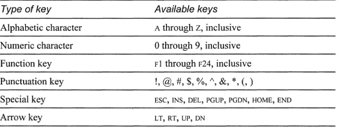
The keyboard
OrCAD printed documentation uses a few special symbols and conventions.
• The keys on your keyboard may not be labeled exactly as they are in this manual. All key names are shown using small capital letters. For example, the Control key is shown as CTRL; the Escape key is shown as ESC.
• Keys are frequently used in combinations or sequences. For example, SHIFT+Fl means to hold down the SHIFT key while pressing Fl. ALT, F, A, means to press and release each of these keys in order: first ALT, then F, then A.
• Arrow keys is the collective name for the UP ARROW, DOWN ARROW, LEFT ARROW, and RIGHT ARROW keys.
• To choose a command from a menu, you can use the mouse or press a key combination. For example: from the File menu, choose Open (ALT, F, o).
About this manual
Text
• Text you are instructed to type is shown in bold. For example, if the manual instructs you to type
*
.dsn, you type an asterisk, a period, and the lowercase letters dsn. The text you type is usually shown in lowercase letters, unless it must be typed in uppercase letters to work properly.• Placeholders for information that you supply (such as filenames) are shown in italic. For example, if the manual instructs you to type cd directoryname, you
type the letters cd followed by a space and the name ofa directory. For example, for a directory named CIRCUITS, you would type cd circuits. • Examples of syntax, netlist output, and source code are displayed in monospace
font.Forexample:/N0001 U1(8) U2(1);.
Capture basics
Part One contains the basic information you need to get started in Capture. It gives you an overview ofthe structure and work environment of Capture, and describes how to open and save projects. Part One includes these chapters:
Chapter 1: Getting started describes how to start Capture.
Chapter 2: The Capture work environment describes the things you'll need to know
to find your way around in Capture. It shows the windows you'll see in Capture: the project manager, the browse window, the schematic page editor, the part editor, the text editor, and the session log. It also introduces you to the toolbar and tool palettes, and general concepts such as selecting and editing objects, and undoing and
repeating actions.
Chapter 3: Starting a project shows how to open a project and work with the
schematic folders and schematic pages in a project. It also shows how to save a project or an individual schematic page.
Chapter 4: Setting up your project
describes how to customize the working environment specific to your system, how to create default settings for new projects, and how to override default settings in existing projects.
Chapter 5: Printing and plotting
describes how to print and plot your design.
Chapter 1
Getting started
This chapter describes how to start OrCAD Capture for Windows.
Starting Capture
The Capture installation process puts Capture in the ORCADWIN folder, and adds OrCAD Design Desktop and Capture to the Programs menu (available from the Start button).
To start Capture
If Windows is not running, type win at the DOS prompt, then perform these steps: 1 From the Start menu, choose Programs. The Programs menu displays. 2 From the OrCAD Design Desktop menu item, choose Capture.
The Capture session frame
Once you start Capture, you see the Capture session frame. You do all your
schematic design and processing within this window.
~i~ 0 rCAD Capture for 'Windows I!!I~
i3
Part 1 Capture basics
The minimized Session Log icon in the lower left portion of the Capture session frame is the session log. The session log provides information about everything you have done. in the current Capture session. Detailed information about this-and the other windows in Capture-is given in chapter 2.
In Capture, each design that you open is in a separate window. You may open as many designs in as many windows as your computer's resources can handle. If you want to work with three schematic pages, orwith three parts, each is available in its own window. If you need to work simultaneously with several designs, you can open them all, and each will have its own project manager window.
Depending on which type of window you have active (an active window is one whose title bar is highlighted), certain buttons on the toolbar and certain items on the menus may be unavailable, since you perform tasks and use tools based upon the type of window that is active. Also, the menus and menu choices vary, depending on which type of window is active.
Chapter 2
The Capture work environment
This chapter describes the things you need to know to find your way around in Capture. It shows the windows you'll see in Capture: the project manager, the browse window, the schematic page editor, the part editor, the text editor, and the session log. It also introduces you to the toolbar, tool palettes, and general Capture concepts such as selecting and editing objects, and undoing and repeating actions.
The project manager
You use the project manager to collect and organize all the resources you need for your project. These resources include schematic folders, schematic pages, part libraries, parts, VHDL files, and output reports such as bills of materials and netlists.
Fb
Note A project doesn't actually contain all the resources. It merely "points to"the various files that the project uses. For this reason, be sure you don't move or delete any files referenced by a project. If you do, the project won't be able to find them.
iii
DESIGN1 "~Eir.
.bogical . (". Eh.l'$icalLJ
FileI
?~.. Hierarchy1
I::;:;
LJ
Design Resources·
.ri]
design1·
[+;13:1
SCHEMATlC1if:
LJ
Design CacheiLJ
Library· LJ
OutputsPart 1 Capture basics
Project manager folders
The project manager provides a graphical display of a project's resources by grouping them into appropriate folders, as described below.
• The Design Resources folder shows a design folder with the design's schematic folders and schematic pages, and a Design Cache folder that shows all the parts used on the schematic pages. Any schematic folders or schematic pages that you create are automatically added to the design folder within the Design Resources folder, but you can also add other files or information using the Project
command on the Edit menu. For example, you can add an existing VHDL file to the design folder and later attach the models within that VHDL file to
hierarchical blocks on a schematic page.
m
See For information about hierarchical designs, see Chapter 6: Design structure.• The Library folder (in the Design Resources folder) shows the schematic part library files you've added to the project using the Project command on the Edit menu.
• The Outputs folder shows the output of Capture's processing tools. Generally, these files include bill of materials reports and technology-specific netlists. Capture adds the appropriate files to this folder as each is created.
Each project may have only one design, but may have multiple libraries. The design may consist of any number of schematics or VHDL models, but it must have a single
root module. The root module is defined as the top level of the design. That is, all
other modules in the design are referenced within the root module.
!
Tip The root schematic folder for a design has a backs lash in its folder icon.Chapter 2 The Capture work environment
Within the project manager, you can expand or collapse the structure you are seeing by double-clicking on a folder, or by clicking on the plus sign or minus sign to the left of a folder. A plus sign indicates that the folder has contents that are not currently visible; a minus sign indicates that the folder is open and its contents are visible, listed below the folder.
Each project you open has its own project manager window. You can move or copy folders or files between projects by dragging them from one project manager window to another (as well as to and from Windows Explorer). To copy rather than move items, press and hold the CTRL key while you drag them. If you close a project manager window, you close the project.
In the project manager's File tab, double-clicking on a schematic folder opens it and displays icons for each schematic page within the schematic folder. Then, if you double-click on a schematic page icon, the schematic page opens in a schematic page editor window. Or, ifthe page is already open, its window becomes active.
Fb
Note If a schematic page is open, you cannot drag its icon to a different location.A design can consist of a single schematic page within a single schematic folder, or a number of schematic pages within a number of schematic folders. A schematic folder "contains" schematic pages in a relationship similar to the relationship between a directory and the files it contains. Files are contained in a directory; schematic pages are contained in a schematic folder.
A schematic page provides a graphical description of the electrical connectivity ofa design. It is made up of parts, wires, and other electrical symbols. A schematic page may also contain borders, title blocks, text, and graphics.
Fb
Note The project manager is also used to manage libraries and the parts they contain. This is covered in detail in Chapter 11: About libraries and parts.Any schematic folders or schematic pages you have selected within an active project manager window limit the scope of various commands, such as the Find and Browse commands on the project manager's Edit menu, the Print command on the project manager's File menu, and the various tools on the Tools menu.
Part 1 Capture basics
Project manager tabs-File and Hierarchy
The project manager provides two ways to display a project's resources.
If you choose the File tab, the project manager displays all the project's folders, schematic folders, and schematic pages.
If you choose the Hierarchy tab, the project manager displays the hierarchical relationship among the project's schematic folders and schematic pages.
Design Resources
.~ .\fulladd.dsn
i~l·l!l FULLADD
, : .. ~ FULLADD.SCH
L~JL:J HALFADD
!
'.15n
HALFADD.SCH. [+1
CJ
Design Cache:···CJ
LibraryFile tab.
iii
fulladd I!II~Ei
;'
'~~f~,~~r~~~~~'
, F::+
IQj FULLADD4-[3.1Qj HALFADD_A (HALFADD.SCH) .'
. '1Qj U1 (74LS08)
.. 1Qj U1 (74LS08)
, .. 1Qj U1 (74LS08)
IQj U2 (74LS04)
, .. 1Qj U2 (74LS04)
i.,,1Qj U3 (74LS32)
±J.1Qj HALFADD_B (HALFADD.SCH)~,
Hierarchy tab.
m
See For information about hierarchical designs, see Chapter 6: Design structure.Chapter 2 The Capture work environment
Project manager options-Logical and Physical
Projects can display in dther logical mode or physical mode, corresponding to the Logical option and Physical option in the project manager. Each of these modes offers a unique method for interpreting your design.
In logical mode, a part may be
referenced multiple times in the design hierarchy; however, only one instance ofthat part exists. For example, in the picture at right, there are three instances ofUl in HALFADD A and three instances of U 1 in
HALF ADD _ B. Any editing changes you make to parts instances apply to the part occurrences as well.
iii
fulladdIl!lIiI
E3
r.
.bogicalr
EhysicalCJ
File ~~a Hierarchyt::::·1Q) FULLADD
'::::flQ) HALFADD_A (HALFADD.SCH)
.IQ) Ul (74LS08)
· .. IQ) Ul (74LS08)
IQ]
U1 (74LS08)' .. IQ]
U2 (74LS04)· .. IQ]
U2 (74LS04)· .. IQ]
U3 (74LS32).IQ]
HALFADD_B (HALFADD.SCH)'IQ]
U1 (74LS08), .. IQ]
U1 (74LS08).. IQ]
U1 (74LS08).. IQ]
U2 (74LS04).IQ]
U2 (74LS04); .. IQ]
U3 (74LS32)IQ]
U3 (74LS32)Logical mode.
Part 1 Capture basics
In physical mode, a part is duplicated each time it is referenced in the design hierarchy. That is, a copy of it is created each time it occurs in the design hierarchy. For example, the three instances ofUl in logical mode (in the previous picture) have now changed to three occurrences (UlA, UlB, and UlC) in HALFADD_A and three occurrences in HALF ADD_B. Notice, also, that the icons for the occurrences are grayed out. This serves as a visual reminder that any editing changes you make to parts in physical mode only apply to the part occurrences: the editing changes do not apply to the part instances.
10 DrCAD Capture for Windows User's Guide
FULLADD
~,.Ia! HALFADD_A [HALFADD.SCH]
L.1a!
U1A [74LSOB]!.Ia!
U18 [74LSOB]'Ia!
U1 C [74LSOB]"Ia!
U2A [74LS04]; ... Ia!
U28 [74LS04]'Ia!
U3A [74LS32]B--Ia!
HALFADD_8 [HALFADD.SCH], .. Ia!
U1A [74LSOB]•... Ia!
U18 [74LSOB]: IQ} U1C [74LSOB]
: ... Ia!
U2A [74LS04]: .. Ia!
U28 [74LS04]: . "IQ} U3A [74LS32]
... Ia!
U38 [74LS32]Chapter 2 The Capture work environment
Part instances and part occurrences
A part instance is a part as it exists in logical mode. Since the part instance may be referenced in one or more schematic pages, any change you make to a part instance affects each schematic page that refers to that part instance. For flat and simple hierarchical designs, this is straightforward: each part instance has a unique reference designator and set of associated properties that apply each time the part instance is referenced.
In a complex hierarchy, a part instance that is referenced more than once in the design will only have one reference designator and set of properties assigned to it, regardless of the number of times it is referenced. This presents a problem when you need to create a netlist for use with Layout or some other board layout tool. Physical mode provides a method to uniquely annotate each occurrence of a part instance. Hence, part occurrence refers to a particular instantiation of a part instance in the netlist.
rn
See For information about simple and complex hierarchical designs, seeChapter 6: Design structure.
RJ
Note You cannot change design connectivity while in physical mode. Any changes to design structure must be performed in logical mode. In physical mode, you can only edit properties for part occurrences.Part 1 Capture basics
When to use physical mode
Physical mode is typically necessary for PCB designs where all parts must be assigned unique reference designators and properties. In fact, in nearly all cases, the
only time you should use physical mode is when you update part references or
properties, or create a netlist for a PCB design that has a complex hierarchical design structure. For FPGA designs, or for PCB designs that use a flat or simple·
hierarchical structure, use logical mode at all times.
The following table summarizes the mode you should use for your design asa function of the structure and the type ofthe design.
Design structure For FPGAlCPLD For PCB designs,
designs, use mode: use mode:
Flat design Logical Logical
Simple hierarchy Logical Logical
Complex hierarchy Logical Physical
Even if your PCB design employs a complex hierarchy you should use physical mode only when you are processing your design (updating references, creating a netlist, updating properties, creating a bill of materials or cross reference report, swapping gates or pins, or assigning part packages). Use logical mode to perform design entry for your PCB design then, when you want to begin processing your design, switch to physical mode.
There is one additional case that requires you to use physical mode: when you cross probe your Capture schematic with its corresponding board layout in Layout.
1m
See For more information about cross probing your schematic with a board layout, see Chapter 18: Using Capture with OrCAD Layout for Windows.Project manager pop-up menus
There are a number of pop-up menu commands available in the project manager window. Using the commands on these pop-up menus, you can open a file or schematic page, or edit and view the properties of the currently selected item. For information on each pop-up menu command, refer to Capture's online help.
Chapter 2 The Capture work environment
The browse window
The browse window displays the items that are found using either the Browse command or the Find command from the project manager's Edit menu. Both the Browse and Find commands apply to all the schematic folders and schematic pages you select in the project manager.
If you double-click on one of the items in the first column ofthe browse window, the schematic page that contains that item displays in the schematic page editor window, with the item selected.
lID FULLADD DSN . BROWSE I!!!I~ E3
Reference haffadd A haffadd=B
U1A 74LS32 C:\()\'PTU ...
You can sort the browse results using the buttons along the top of the browse window. When you choose one of the buttons, the rows of information in the browse window are reordered alphabetically based on the information in the column you are sorting. Each type of browse provides a different set of sort buttons. For example, the sort buttons provided for parts are part reference, part value, source part, source library, schematic page, and schematic folder, but the sort buttons provided for nets are net alias name, net name, schematic page, and schematic folder.
Once the sort results display, you can adjust the column widths by dragging the vertical lines between the column names to the left or right. You can close or minimize the browse window using the standard Windows buttons in the upper right comer of the window.
Part 1 Capture basics
The schematic page editor
The schematic page editor window is used to display and edit schematic pages. You can place parts, wires, buses, and draw graphics. The schematic page editor has a tool palette that you can use to draw and place everything you need to create a schematic page. You can print from within the schematic page editor.
CARRYJN c::;;
)( C=>'~--
Y C=>'~-__
The part editor
Chapter 2 The Capture work environment
The part editor window is used to create and edit parts.
----i~'D"
2i
---i: ...
~.... ..
-~~N_··.···· •
7, :
. {VoIlue}
---~
... : . '.... /.;;
From the View menll of the part editor you can choose either Part or Package. In Part view you can:
• Create and edit parts and symbols, then store them in new or existing libraries. • Create and edit power and ground symbols, off-page connector sytpbols, and
title blocks.
• Use the tool palette's electrical tools to place pins on parts, and its drawing tools to draw parts and symbols. (See Part editor tool palette later in this chapter.) Package view shows you the entire package. You can edit the properties of the entire package, such as part reference, prefix, part alias, and so on. You cannot edit individual parts in this view, but you can select individual parts to edit by double-clicking on them.
W
See also See Chapter 11: About libraries and parts for complete definitions ofparts and packages. See Chapter 12: Creating and editing parts for a complete description of the part editor.
Part 1 Capture basics
The text editor
Use the text editor to create or view VHDL files or other text files within Capture. VHDL keywords and comments are displayed in the colors you specifY in the Text Editor tab in the Preferences dialog box (from the Options menu, choose
Preferences).
LIBRARY IEEE;
USE IEEE.stdJogic_1164.all; ENTITY FOE IS PORT (
o :
IN stdJogic; E : IN stdJogic; ClK: IN stdJogic; C : IN stdJogic;To create a new VHDL file in the text editor
~
From the File menu, choose New, then choose VHDL File. A blank VHDL file displays in the text editor.To open a VHDL file in the text editor
1 From the File menu, choose Open, then choose VHDL File. The Open VHDL File dialog box displays.
2 Select a file, then choose the OK button.
or
1 In the project manager, select a VHDL file. 2 From the pop-up menu, choose Edit.
m
See For more information on editing VHDL files in the text editor, see Capture's online help.Chapter 2 The Capture work environment
The session log
The session log lists the events that have occurred during the current Capture ses-sion, including messages resulting from using tools. To display context-sensitive help for an error message, put the cursor in the error message line in the session log and press Fl.
The ruler along the top displays in either inches or millimeters, depending on which measurement system (U.S. or Metric) is selected in the Windows Control Panel. You can add tab settings to the ruler by clicking in the ruler bar, drag the tabs to different positions, or remove them by dragging them down into the session log window. Your tab settings are saved and used each time you start Capture.
It
Session Log1!Il!] EJ
* ...
* Bill Of Materials *
""':lA.U ;tlJ::U 'kJd .. U .JtlJdo:lAl:ht:tt:tAtA'UtottA.U Jolt t:tAt:t"':t:tAtAJ::t A:lA:t:tAAAAAAAA ... :t:tAA Performing BOM.
BOM Done.
...
You can search for information in the session log using the Find command on the Edit menu. You can also save the contents of the session log to a file, which is useful when working with OrCAD's technical support staffto solve technical problems. The default filename is SESSION.TXT.
~
Tip
To clear the session log, choose Clear Session Log from the Edit menu, or use the CTRL +DEL shortcut key combination.Part 1 Capture basics
The toolbar
Capture's toolbar is dockable (that is, you can select an area between buttons and drag the toolbar to a new location) and resizable, and displays tooltips for each tool. By choosing a tool button, you can quickly perfonn a task. If a tool button is dimmed, you can't perfonn that task in the current situation.
Some of the tools operate only on what you have selected, while others give you a choice of either operating on what is selected or expanding the scope to the entire project. The table below summarizes the tools on the toolbar. The tasks that these tools perfonn are described throughout this manual.
Tool Name
:jtJ
New OpenSave
c!j
.
~
.
1J
. . Cut .~
Copy.
!lj
PasteBJ
Undo._'."
.
£1
Redo...
~;.~
Zoom In~
Zoom OutDescription
Create a new document based on the active document. Similar to the New command on the File menu.
Open an existing project or library. Similar to the Open command on the File menu.
Save the active schematic page or part. Equivalent to the Save command on the File menu .
Print the active schematic page or part. Equivalent to the Print command on the File menu .
Remove the selected object and place it on the Clipboard. Equivalent to the Cut command on the Edit menu .
Copy the selected object to the Clipboard. Equivalent to the Copy command on the Edit menu .
Paste the contents of the Clipboard at the cursor. Equivalent to the Paste command on the Edit menu.
Undo the last command perfonned, if possible. Equivalent to the Undo command on the Edit menu .
Redo the last command perfonned, if possible. Equivalent to the Redo command on the Edit menu .
Zoom in to see a closer, enlarged view. Equivalent to choosing Zoom and In from the View menu.
Zoom out to see more of your document. Equivalentto choosing Zoom and Out from the View menu.
Tools on the Capture toolbar (page 1 of 2).
Tool Name
Zoom Area
Zoom All
Chapter 2 The Capture work environment
Description
Specify an area of the schematic page or part to enlarge to fill the entire window. Equivalent to choosing Zoom and Area from the View menu.
View the entire document. Equivalent to choosing Zoom and All from the View menu.
Update Part Assign part references to parts on the selected schematic References pages. Equivalent to the Update Part References command
EJ.
Gate and Pin Swap.
1j
Design Rules Check:~
Create NetlistEU
Cross.
:S:~<~.:.; Reference~
Bill of; . . , Materials
.
~
Project Manager
, I
Help-!J
Topicson the Tools menu. .
Back annotate the selected schematic pages. Equivalent to the Gate and Pin Swap command on the Tools menu . Check for design rules violations on the selected schematic pages. Equivalent to the Design Rules Check command on the Tools menu.
Create a netlist for the selected schematic pages. Equivalent to the Create Netlist command on the Tools menu.
Create a cross reference report for the selected schematic pages. Equivalent to the Cross Reference command on the Tools menu.
Create a bill of materials report for the selected schematic pages. Equivalent to the Bill of Materials command on the Tools menu .
Display a project manager window for the active document, providing an overview of project contents. Equivalent to choosing a project manager window by number from the Window menu.
Open online help. Equivalent to the Help Topics command on the Help menu.
Tools on the Capture toolbar (page 2 of 2).
Displaying or hiding the toolbar
You can hide the toolbar, then display it again when you need it.
To display or hide the toolbar
~
From the schematic page editor's View menu, choose Toolbar (ALT, v, T).or
From the part editor's View menu, choose Toolbar (ALT, v, T).
Part 1 Capture basics
The tool palettes
Capture has two tool palettes: one for the schematic page editor window and one for the part editor window. Both tool palettes are dockable (that is, you can click on an area between buttons and drag a tool palette to a new location) and resizable, and display tooltips that identify each tool. While the drawing tools on the two tool palettes are identical, each tool palette has different electrical tools. After you choose a tool (and, in the case of some tools, after you respond to the tool's dialog box), you press the right mouse button to display a context-sensitive pop-up menu.
The schematic page editor tool palette
The first group of tools on the tool palette are electrical tools, used to place
electrical-connectivity objects. The second group of tools are drawing tools, used to create graphical objects without electrical connectivity.
The tools on the schematic page editor tool palette are described in the table below. For descriptions of how to use the electrical tools, see Chapter 7: Placing, editing,
and connecting parts and electrical symbols. For descriptions of how to use the
drawing tools, see Chapter 8: Adding and editing graphics and text.
Tool . Name Select
Part
Wire
Net Alias
Description
Select objects. This is the normal mode.
Select parts from a library for placement. Equivalent to the Part command on the Place menu.
Draw wires. Press SHIFT to draw non-orthogonal (not a multiple of 90°) wires. Equivalent to the Wire
command on the Place menu.
Place aliases on wires and buses. Equivalent to the Net Alias command on the Place menu.
Tools on the schematic page editor tool palette (page 1 of 2).
Tool
.±J
;L:2,1
1fB
•... :."'.' ... '.:1
16
:.' :.:. ,:.';"0,: .. , •.··•· .. ···1
.2J
'. :" i ..
.i~.
:'. :·f·.·.:~ Name Bus Junction Bus Entry Power Ground Hierarchical Block Hierarchical Port Hierarchical Pin Off-Page Connector No Connect Line Polyline Rectangle Ellipse Arc Text
Chapter 2 The Capture work envir,onment
Description
Draw buses. Press SIDFT to draw non-orthogonal buses. Equivalent to the Bus command on the Place menu . Place junctions. Equivalent to the Junction command on the Place menu.
Draw bus entries. Equivalent to the Bus Entry command on the Place menu.
Place power symbols. Equivalent to the Power command on the Place menu.
Place ground symbols. Equivalent to the Ground command on the Place menu.
Place hierarchical blocks. Equivalent to the Hierarchical Block command on the Place menu.
Place hierarchical ports on schematic pages. Equivalent to the Hierarchical Port command on the Place menu.
Place hierarchical pins in hierarchical blocks. Equivalent to the Hierarchical Pin command on the Place menu.
Place off-page connectors. Equivalent to the Off-Page Connector command on the Place menu.
Place no-connect symbols on pins. Equivalent to the No Connect command on the Place menu.
Draw lines. Equivalent to the Line command on the Place menu .
Draw polylines. Press SHIFT to draw non-orthogonal poly lines. Equivalent to the Polyline command on the Place menu.
Draw rectangles. SHIFT constrains to a square. Equiva-lent to the Rectangle command on the Place menu. Draw ellipses. SHIFT constrains shape to a circle. Equivalent to the Ellipse command on the Place menu.
Draw arcs. Equivalent to the Arc command on the Place menu.
Place text. Equivalent to the Text command on the Place menu.
Tools on the schematic page editor tool palette (page 2 of 2).
Part 1 Capture basics
The part editor tool palette
The fIrst group of tools on the part editor tool palette are electrical tools, used to place pins and IEEE symbols. The second group of tools are drawing tools, used to create graphical objects without electrical connectivity.
The tools unique to the part editor tool palette are described in the table below. The drawing tools are described in the previous section Schematic page editor tool
palette.
For infonnation on how to use the electrical tools, see Chapter 12: Creating and
editing parts. For infonnation on how to use the drawing tools, see Chapter 8: Adding and editing graphics and text.
Tool Name
IEEE Symbol
Pin
Pin Array
Description
Place IEEE symbols on a part. Equivalent to the IEEE Symbol conunand on the Place menu.
Place pins on a part. Equivalent to the Pin conunand on the Place menu.
Place multiple pins on a part. Equivalent to the Pin Array conunand on the Place menu.
Tools on the part editor tool palette.
Displaying or hiding a tool palette
Like the toolbar, you can hide a tool palette, then display it again when you need it.
To display or hide a tool palette
~
From the schematic page editor's View menu, choose Tool Palette (ALT, Y, p).or
From the part editor's View menu, choose Tool Palette (ALT, Y, p).
Chapter 2 The Capture work environment
The status bar
Left field
Center field
Right field
The status bar is located at the bottom of the Capture session frame, and reports on current actions, number of items selected,. zoom scale, and pointer location.
Displays descriptions of selected tools or menu items, prompts, or the current status.
Displays the number of items selected in the schematic page editor or part editor.
Fb
Note When a session log or a project manager window is active, the center field of the status bar doesn't display.Displays the current scale and pointer location (such as: Scale=50% X=10.0 Y=5.0). The location in the schematic page editor is measured in either inches or millimeters, depending on the Units settings in the Page Size tab in the Schematic Page
Properties dialog box. The location in the part editor is measured in grid units.
Displaying
or
hiding the status bar
You can hide the status bar, then display it again when you need it.
To display or hide the status bar
~
From the schematic page editor's View menu, choose Status Bar (ALT,v,
s).or
From the part editor's View menu, choose Status Bar (ALT, v, s).
Part 1 Capture basics
Using help and the online tutorial
Capture's online help includes information to help you become familiar with Capture. You can access help from the menu bar in the session frame, by choosing the Help button in a dialog box, or by pressing F 1.
Topics include:
• Explanations and instructions for common tasks.
• Descriptions of menu commands, dialog boxes, tools on the toolbar and tool palettes, and the status bar.
• Netlist format samples, error messages, and glossary terms. • Reference information.
• Product support information.
You can get context-sensitive help for an error message by placing your cursor in the error message line in the session log and pressing FI.
Capture's online tutorial takes you through a series of self-paced, interactive lessons. You can practice what you've learned by going through the tutorial's specially designed exercises.
Using the Accessories menu
You can use extensions to the OrCAD-supplied functionality of Capture if you purchase software developed by associates of Or CAD. These associates create .DLL files that address specific Capture functionality, such as customized netlisting. The associates configure their .DLL files so that they are listed as menu choices on the Accessories menu, available in either the project manager window or the schematic page editor window, once you install a third-party extension. OrCAD's Enterprise Edition software displays commands in this menu.
Chapter 2 The Capture work environment
Selecting and deselecting objects
Once you select an object, you can perfonn operations on it, including moving, copying, cutting, mirroring, rotating, resizing, or editing. You can also select mUltiple objects and edit them, or group them into a single object. Grouping objects maintains the relationship among them while you move them to another location.
Wi
See You can edit the properties of a group of objects using the spreadsheet editor. See Using the spreadsheet editor to edit properties in this chapter.This section describes different ways to select individual objects and groups of objects in both the schematic page editor and the part editor.
To select an object
I:!:>
Position the pointer on the object and click the left mouse button. The object displays in the selection color.~
Tip To change the selection color: from the Options menu, choose Preferences, then choose the Colors tab. Click the left mouse button over the Selection color. Select a new color from the color palette window, choose the OK button to dismiss the color palette, then choose the OK button to dismiss the dialog box.To select multiple objects
I:!:>
For each object to select, position the pointer on the object and press CTRL while you click the left mouse button. Every object in the selection set displays in the selection color.~
Tip To select a part, click within the part itself. To select a graphical object, click on an outside edge of the object (it is easier to do this if you zoom in).To select all objects in an area
1 From the tool palette, choose the selection tool.
2 Click on an area where there are no objects or parts to deselect any items that may be selected. Move the pointer to one comer of the area to select. Press and· hold the left mouse button while you drag the mouse to the opposite comer, then release the left mouse button. Every object in the selection set displays in the selection color.
~
Tip You can control whether the selection set includes all objects intersected by your selection rectangle or only those objects entirely inside the selectionrectangle. From the Options menu, choose Preferences, then choose the Select tab. Select one of the Area Select options, then choose the OK button.
Part 1 Capture basics
To select all objects on a schematic page or part
~
From the Edit menu, choose Select All. All objects display in the selection color.Fb
Note The selection set behaves as ifit is one object, so that you can move, copy, cut, delete, mirror, or rotate the entire selection set. Be aware, however, that the Select All command also selects the title block on the schematic page. If you copy or move the selection set, you could create a duplicate title block, or inadvertently move the title block off the schematic page.To deselect objects
~
Click on an area where there are no objects. Selected objects become deselected. Note that a part occupies a rectangular area encompassing all its graphics. This means that a part may occupy a larger area than is initially apparent.To remove one object from a selection set
~
Place the pointer over the object, press CTRL, and click the left mouse button.Fb
Note To select from objects stacked atop one another, position the pointer over the stack of objects and press the TAB key while you click the left mouse button. This cycles through the objects in the stack.Grouping objects
Use the Group command on the Edit menu to group multiple objects into one selectable object. This is a convenient way to maintain the relationship among several objects while moving them to another location. You can nest groups,
meaning a group can contain other groups as well as objects. The Group command is only available when multiple objects are selected.
Fb
Note Objects remain grouped until you ungroup them or close all windows on the schematic page or part that contains them.To group multiple selected objects
1 Select the objects you want to group, as described in the previous section. 2 From the Edit menu, choose Group. You can move the objects as a group. 3 When you are through manipulating the objects as a group, you can ungroup
them. From the Edit menu, choose Ungroup.
Editing objects
Chapter 2 The Capture work environment
Each object has a set of properties, and you can edit the value associated with each property. For some objects (parts, packages, hierarchical blocks, pins, nets, and buses), you can add your own user-defined properties.
Fb
Note You cannot add user-defined properties to graphic objects, bookmarks, IEEE symbols, no-connect symbols, net aliases, power and ground symbols, off-page connectors, or bus entries.Properties can be used to store information, such as a part's value or reference. They can also be used to define the appearance of an object. For example, properties are used to define the color, line weight, and fill of graphic objects.
For some objects-such as wires, buses, lines, ellipses, rectangles, and so on-you can edit the object's size and shape by clicking on it and dragging its resize handles.
Editing properties
Capture uses properties to describe objects. A property consists of a property name (for example, Part Value or Part Reference) and a property value (for example, TIP3! C or Q2).
m
See For a sample listing showing property names and property values, see Capture's online help topic Bill of Materials sample report file. Each type of object (text, wire, and so on) has its own set of properties. For information about editing specific properties of an object, see Capture's online help topic Editingproperties.
To edit an object's properties
1 Double-click on the object. A dialog box containing properties for the object displays.
2 Edit the properties, then choose the OK button. or
1 Click on the object to select it.
2 From the Edit menu, choose Properties (ALT, E, I). A dialog box containing properties for the object displays.
3 Edit the properties, then choose the OK button.
Part 1 Capture basics
Using the spreadsheet editor to edit properties
The properties of a group of objects can be edited using the spreadsheet editor. In the spreadsheet editor, you can edit:
• Multiple parts • Pins on parts • Hierarchical ports • Hierarchical pins
• Wires • Buses • Nets
• Off-page connectors • DRC markers • Bookmarks
• A set of objects selected from the Browse window
To edit an object's properties using the spreadsheet editor 1 Select the group of objects, as described earlier in this chapter.
2 From the Edit menu, choose Properties (ALT, E, I). Note that if the objects in the selection set are not ofthe same type, the Properties command is unavailable. The spreadsheet editor displays. You can use the spreadsheet editor to: • Click the left mouse button to select a cell for copying or pasting.
Double-click to select the cell for editing.
• Click on a row or column heading to select the entire row or column. • With one or more cells selected, press and hold the SHIFT key while you
click on an adjacent cell to extend the selection set.
• Choose the New button to display the New Property dialog box. Enter the property name. If you want all members of the current selection set to have a particular value, enter the value also.
3 Choose the OK button to close the spreadsheet editor.
~
Tip To assign a cell's value to all ofthe cells within the same column in the spreadsheet editor, select a cell's value, choose Copy, select the entire column, and choose Paste.Chapter 2 The Capture work environment
Adding user-defined properties
You can add user-defined properties to electrical objects. For example, if you want to include the name of the supplier, you create a user-defined property for the information. You can add as many user-defined properties as you like, edit them as described in the section Editing properties, make them visible or invisible using the Display Properties dialog box (choose the Display button in the User Properties dialog box), and remove them if you no longer need them.
Fb
Note You cannot add user-defined properties to graphic objects, bookmarks, IEEE symbols, no-connect symbols, net aliases, power and ground symbols, off-page connectors, or bus entries.If you add a user-defined property to one part in a homogeneous package (multiple parts that are graphically identical), all parts in the package inherit the property and its value. If you add a user-defined property to one part in a heterogeneous package (multiple parts that are graphically different or contain different numbers of pins), the other parts in the package are not affected. You can also edit properties on multiple-part packages, in which case the changes appear on every part in the package, and on every part instance. You cannot add user-defined properties to packages.
To add a user-defined property 1 Select an object.
2 From the Edit menu, choose Properties. An appropriate dialog box, such as the Edit Part dialog box, displays.
3 Choose the User Properties button. The User Properties dialog box displays. 4 Choose the New button. The New Property dialog box displays.
5 Enter a name and a value for the new property, then choose the OK button three times to close all the dialog boxes.
You can include a user-defined property in a netlist or a Bill of Materials report by specifying its property name, in curly braces, in a combined property string.
m
See For information about using combined property strings, see Capture's online help.Part 1 Capture basics
Moving and resizing graphic objects
Before you can move or resize a graphic object, you must first select it. A selected object has resize handles that you use to change the size of the graphical object.
To resize and move objects 1 Select the object to resize or move.
2 To resize the object, press the left mouse button on a resize handle, and drag the handle until the object is the size you would like it. Release the mouse button. or
To move the object, press the left mouse button anywhere on the object-except on a resize handle-and drag the object until it is where you want it. Release the mouse button.
3 To deselect the object, click in an area where there are no parts or objects.
m
See also For descriptions of other ways to manipulate objects, see Chapter 8:Adding and editing graphics and text.
Undoing, redoing, and repeating an action
You use the Undo command to undo your action. To repeat an edit action, use the Repeat command. For example, you might move a selected object five grid units, then realize you also need to move a different object the same distance. Select the second object, then from the Edit menu, choose the Repeat command. You can use the Undo, Redo, and Repeat commands with the following actions:
• Placing objects
• Deleting objects (except for the Repeat command) • Copying objects
• Moving objects • Resizing objects • Rotating objects • Mirroring objects
To undo an action
~
From the Edit menu, choose Undo.To undo an Undo command
~
From the Edit menu, choose Redo.Chapter 2 The Capture work environment
To repeat a command 1 Perform the command once. 2 From the Edit menu, choose Repeat.
~
Tip You can use the Repeat command to align objects or to quickly create repetitive structures such as buses.To repeat a place operation
1 Place an object on a schematic page.
2 Press CTRL and drag the object to a new location. This creates a copy of the
object. Leave the object selected.
3 From the Edit menu, choose Repeat. The pointer repeats the relative move in step 2 and an additional object is placed.
Chapter 3
Starting a project
All the schematic folders and schematic pages in a design, as well as libraries, VHDL files, and output reports for a project are stored in a single file that has an .OPJ extension. A project contains one or more schematic folders, in which one or more schematic pages are stored. A project also contains a design cache, which is like an embedded library-it contains a copy of all the parts and symbols used on the schematic pages.
Fb
Note Parts reside in a library the same way schematic pages reside in schematic folders. Symbols and title blocks also reside in libraries. A project can use any number of libraries, and a library can be included in any number of projects. However, a project may have only one design (.DSN).Creating new designs, libraries, and VHDL files
You can create new designs, libraries, and VHDL files.
To create a new design
1 From the File menu, choose New, then choose Design.
2 The design opens in the project manager and a new schematic page displays.
To create a new library
1 From the File menu, choose New, then choose Library.
2 The library opens in the project manager and a Library Cache folder is added to the project manager.
m
See For information on how to create parts for inclusion in a library, seeChapter 12: Creating and editing parts.
To create a new VHDL file
1 From the File menu, choose New, then choose VHDL File. 2 The VHDL file opens in Capture's text editor.
Part 1 Capture basics
To create a VHDL file and add it to a project
1 From the project manager's Design menu, choose New VHDL File (ALT, D, v). The file opens in the text editor, and a dialog box asking if you want to add the file to the project displays.
2 Choose the Yes button. The Save As dialog box displays.
3 Select a directory for the file and supply a filename. By default, the VHDL file's name is VHDLn.VHD (where n is an integer).
4 Choose the Save button. The file is saved and put into the project's Design Resources folder.
Chapter 3 Starting a project
Opening files
You can open an existing design, library, project, or VHDL file.
~
Tip The four files that were last opened are listed at the bottom of the File menu. To open one of these files, select it from the File menu.To open an existing design
1 From the File menu, choose Open, then choose Design. The Open Design dialog box displays.
2 Select a design (.DSN) or type a name in the File name text box, then choose the Open button. The design opens in the project manager.
To open an existing library
1 From the File menu, choose Open, then choose Library. The Open Library dialog box displays.
2 Select a library (.OLB) or type a name in the File name text box, then choose the Open button. The library opens in the project manager.
To open an existing project
1 From the File menu, choose Open, then choose Project. The Open Project dialog box displays.
2 Select a project (.OPJ) or type a name in the File name text box, then choose the Open button. The project opens in the project manager.
To open an existing VHDL file
1 From the File menu, choose Open, then choose VHDL File. The Open VHDL File dialog box displays.
2 Select a VHDL file (.VHD) or type a name in the File name text box, then choose the Open button. The VHDL file.opens in Capture's text editor.
Part 1 Capture basics
Working with files in a project
Using the project manager, you can add or delete project files.
To add a file to your project
1 In the project manager, select the folder to which you want to add a file. 2 From the Edit menu, choose Project (ALT, E, R). The Add File to Project Folder
dialog box displays.
3 Select the file you want to add and choose the Open button. The file is added to the project.
Or
~
Drag the file from the Windows Explorer into the folder in the project manager.R:J
Note You can also add files to your project interactively. When you create a design using the New command on the File menu, it is placed in the project manager's Design Resources folder. Note, however, that your project can include only one design (.DSN) file. If you try to add a second .DSN file to your project, the Overwrite dialog box displays, asking if you want to replace the existing design.To delete a file from a project
1 In the project manager, select the file you want to delete. 2 Press the DELETE key. The file is removed from the project.
Chapter 3 Starting a project
Saving projects, designs, and libraries
When the project manager window is active, you can save a new or existing project, design, or library. The Save command saves all open documents referenced by the project, as well as the project itself.
The Save As command saves files depending on what you have selected in the project manager.
•
•
a
If one or more designs or libraries are selected, you are prompted to save each file in turn.
Ifno top-level folders (Design Resources or Outputs) are selected, and items other than designs or libraries are selected, the Save As command is
unavailable.
Ifno designs or libraries are selected in the project manager, you are prompted to save the project.
m
See To protect your work in the event of a system crash or power outage, you can enable Autosave, and set the interval at which your design, library, or VHDL file is saved. For information about the Autosave option, see Setting miscellaneousoptions in Chapter 4.
To save a new design or library
With the design or library selected in the project manager, from the File menu, choose Save (ALT, F, s). The Save As dialog box displays.
2 Enter a name for the design or library in the File name text box, specifY a location, then choose the Save button.
The design or library is saved, and the project manager remains open.
Fb
Note If you choose Save when a schematic page window is active, only that page's design is saved, not the entire project. However, when you attempt to close the project, a dialog box asks if you want to save any project files that have been edited but not yet saved.To save an existing project
~
From the File menu, choose Save (ALT, F, s).The project is saved, and remains open in the project manager.
Part 1 Capture basics
Closing a project
When the project manager window is active, you can close a project without quitting Capture, or you can close and save your project as you quit.
To close a project
~
From the project manager's File menu, choose Close Project (ALT, F, c).When you close a project, a dialog box displays, asking if you want to save your changes.
To quit Capture
~
From the project manager's File menu, choose Exit (ALT, F, x).When you choose the Exit command, a dialog box displays, asking if you want to save your changes.
Chapter
4
Setting up your project
Capture provides different levels of configuration. Using commands on the Options menu, you can:
• Customize the working environment specific to your system (using Preferences).
a Create default settings for new designs (using Design Template). These settings stay with the design even if it is moved to another system with different preferences.
• Override settings in individual designs (using Design Properties) or individual schematic pages (using Schematic Page Properties).
Regardless of which Capture window is active, the Options menu has a Preferences command and a Design Template command. In addition, the Options menu contains commands specific to the current active window. For example, the project manager's Options menu contains the Design Properties command, while the schematic page editor's Options menu contains the Schematic Page Properties command.
The settings in the Preferences dialog box determine how Capture works on your system, and persist from one Capture session to the next because they are stored in the Capture initialization (.INI) file on your system. If you pass projects to others, they won't inherit your Preferences settings. This means that you can set colors, grid display options, pan and zoom options, and so on to your liking and be assured that your settings will remain, even if you work on a project created on another system. The Design Template dialog box determines the default characteristics of all the projects created on your system. Because a new project inherits characteristics from the current Design Template settings, it's a good idea to check the settingS before you create a new project. .
Once you begin working on a project, you can customize its particular characteristics by choosing Design Properties from the Options menu when you are in the project manager, or Schematic Page Properties when you are in the schematic page editor.
Part 1 Capture basics
Defining your preferences
The options that you define in the tabs of the Preferences dialog box affect how Capture works with your projects.
• ColorslPrint. Set up colors for objects such as off-page connectors, hierarchical blocks and ports, text, title blocks, and so on, and specifY which objects will be printed or plotted. You can also change the background color and the color of the grid.
• Grid Display. Select dots or lines for your grid, and whether to display or print your grid. You can select whether to have your pointer snap to grid as you place objects. You can set these options independently for the schematic page editor and the part editor.
• Pan and Zoom. Define how you want autoscrolling to work, and what the zoom factor should be. You can set these options independently for the schematic page editor and the part editor.
• Select. Define whether you want to select objects enclosed by a selection rectangle or objects intersecting a selection rectangle, the maximum number of objects to display at high resolution while dragging, and whether to show the tool palette. You can set these options independently for the schematic page editor and the part editor.
• Miscellaneous. Define the default fill, line style and width, and color for graphic objects, define the font used in the project manager and session log, render TrueType fonts with strokes (for printing and plotting), and set whether to autos ave your project and how often. In addition, you can enable intertool communication, which is the method that Capture uses to communicate with other OrCAD software, such as OrCAD Layout for Windows.
• Text Editor. Define which (if any) VHDL keywords are highlighted, and the font and tab settings used within the text editor.
Chapter 4 Setting up your project
Defining colors/print options
You control the color in which different schematic page objects display by using the ColorslPrint tab in the Preferences dialog box.
Fb
Note The color that you select for Title Block is also the color used for borders and grid references.If an object's Print box is checked, the object is printed or plotted. Clicking on a check box toggles its check mark on or off. Objects are always displayed on your screen, regardless of the setting of their check boxes.
Preferences EJ
·.irf~~I·~;~:D~~J··p~~;1SI:.~~~.ltH~);;t)~m~·I.·.:
P"_~':,"f~~Mode
.To define an object's color
1 From the Options menu, choose Preferences (ALT, 0, p), then choose the ColorslPrint tab.
2 Click on the color of an item. The color palette window opens. 3 Select a new color. Choose the OK button to dismiss the color palette. 4 Choose the OK button.
Fb
Note The color that you select for Graphics defines the color for lines,polylines, and arcs drawn in the schematic page editor, and for all graphics drawn in the part editor. If you change the Color option in the Miscellaneous tab, then rectangles, ellipses, and closed polyline shapes that you draw in the schematic page editor are created in that color. Lines, polylines, and arcs, however, are drawn in the color you chose for Graphics in the ColorslPrint tab.
Part 1 Capture basics
Controlling the grid
You can control whether Capture displays or prints a grid independently in the schematic page editor and the part editor, and whether the grid uses dots or lines. You can also specifY whether the pointer snaps to grid in each editor.
fii'~
Caution If you disable the Pointer snap to grid option while you are drawing, be sure to enable it before you place electrical objects. Otherwise, your part pins may be placed off-grid, making it difficult to connect them properly.To control the grid
1 From the Options menu, choose Preferences (ALT, 0, p), then choose the Grid Display tab.
2 For the schematic page editor and the part editor, specifY: • Whether to display the grid, print the grid, or both. • Whether the grid uses dots or lines.
• Whether the pointer snaps to grid as you place objects. 3 Choose the OK button.
~
Tip You can also show or hide the grid using the Grid command on the View menu in the schematic page editor or the part editor.Chapter