· SANDERS 620* DATA DISPLAY SYSTEM
stand alone remote terminal
REFERENCE MANUAL
FIRST EDITION
an evol utionary step in data communications
BAA
SANDERS
ASSOOATES,INC.
DATA SYSTEMS DIVISION
DANIEL WEBSTER HIGHWAY, SOUTH - NASHUA, NEW HAMPSHIRE 03060
620 DATA DISPLAY SYSTEM REFERENCE MANUAL
TABLE OF CONTENTS
Section Introduction Configuration Options Functional Description General Keyboard
CRT Translation Section Dynamic Memory 620 System Code Set Edit Controller Hard-Copy Option I/O Controller
Timing Considerations
Null Formulas
Format Type Mode Nulls Type Mode Nulls
Conversation Type Mode Nulls
Programming Considerations for Use of 620 With IBM System/360
General
OS BTAM - (Remote Connection) OS QT AM - (Remote Connection) DOS BT AM - (Remote Connection) DOS QT AM - (Remote Connection)
Device Dependent Module (DDM) Description Message Processing Macros
Interface Requirements and Characteristics
Hardware Interface
Software Interface With IBM System/360
Installation Planning Data
General
Physical Specifications AC Power
Ambience
Appendices
A. Specifications for 620 System Components
Display Terminal Keyboard
B. Summary Specifications of 620 System Peripheral and Auxiliary Equipment
TABLE OF CONTENTS (CONT)
Section
Model 716 Serial Distributor Summary Specifications
Model 731 Display Communication Buffer Summary Specifications
C. Translation Tables
Figure 1 2 3 4 5 6 7 Table 1 2 3 4 5 6
LIST OF ILLUSTRATIONS
Typical Remote Configuration Expandable Remote Configuration Typical Local Configuration
Simplified Functional Block Diagram Racetrack Pattern
620 System Code Set 620 Terminal Dimensions
Display and Edit Options Input/Output Options Edit Operations
Title
LIST OF TABLES
Title
displayed characters
familiar keyboard
hard-copy
fonnat mode
conversation mode
INTRODUCTION
The Sanders 620 Data Display System is a complete, stand alone, cathode ray tube (CRT) terminal that performs high speed entry and retrieval operations with digital central computer systems from a remote location via a dataphone modem. The 620 system may be used independently or to complement the Sanders 720 Series multi-station display systems to provide instant visual access to stored computer data and as a data inputting station.
The 620 System employs standard ASCII coding and can display messages containing up to 780 characters, positioned in any of 2048 locations on horizontal screen models, or any of 2080 locations on vertical screen models. Displayed characters of high definition are formed from continuous strokes in a flicker-free presentation due to the unique Sanders character writing method and the high, 60 Hertz, refresh rate.
The familiar typewriter-style keyboard furnishes the operator with many special features which allow fast, accurate editing and fonnatting of data. An electrical keyboard interlock allows only the code of the first key depressed to be entered into the 620 memory, when more than one key is depressed at a time. A "roll-off' feature allows the code of the second key to be entered into memory after the first key is released, when two keys are depressed at one time. The keyboard contains 42 alphanumeric and special symbol keys, up to 19 control, function and mode keys, and a space bar. Lamps are proVided to indicate power on and operational modes.
Flexibility of application is made possible by the addition of selected optional hardware. The options can be included when the 620 Display System is shipped to the user or, in most cases, added at a later time to adapt the system to suit the user's new requirements. All options are contained within the 620 Display System cabinet.
The Hard-Copy option provides for Teletypewriter printout of the data displayed on the screen. This option is contained within a printed circuit module. The Teletypewriter is connected directly to the 620 System unit.
The Format Mode option allows the use of two separate, superimposed data fields on the screen; a fixed field and a variable field. The fixed field can be a fonnat of headings, rows and columns, or questions. The variable field then would be composed of answers or fill-ins. The operator can enter and retrieve data in the variable field, and only the variable field will be communicated with the computer. The Fonnat Mode option includes a Vertical and a Horizontal Tab. The Horizontal Tab establishes a line segment which is horizontally separated from the preceding text by four spaces. The Vertical Tab displaces the succeeding test vertically down four lines. The Vertical and Horizontal tabs use only one character space in memory.
Peripherals
hard-copy option
CONFIGURATION
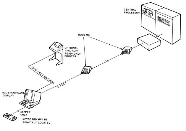
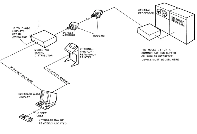
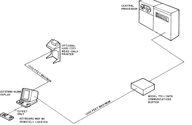
The 620 Data Display System is a stand-alone terminal. All of the control, editing and interface electronics are contained within the terminal cabinet; no control unit is required. With the plug-in keyboard connected, only the appropriate transmission device is needed for access to the central processor. Figures I, 2, and 3 illustrate three possible configurations.
Remote operation via a modem may utilize dataphones on common carrier telephone lines or datasets on dedicated lines. The modem should be within 10 cable feet of the 620 terminal. The Sanders Model 716 Serial Distributor allows up to sixteen 620 Display terminals to share one modem and may be located up to 1000 cable feet from the 620. The central processor channel must contain a suitable serial interface that is compatible with the modem used. When the central processor is an IBM 360, the Sanders Model 731-1 Data Communications Buffer may be used for the serial interface in either local or remote application. Locally, the 731 may be up to 1000 cable feet from the 620. The 731 will interface from one to eight lines to the IBM 360 processor. Summary specifications for the 620 Data Display System, the 716 Serial Distributor and the 731 Data Communications Buffer are provided in the appendices of this manual.
OPTIONS. The 620 System modular construction lends itself to versatile customer specified options which, in most cases, can be obtained by interchanging modules. For example, a read-only teletype printer can be connected to the 620 terminal for hard-copy of display screen data when a hard-copy buffer module is inserted into the card rack and the keyboard contains the copy key. As previously mentioned, keyboards are the plug-in type and are interchangeable.
IOFEET ONLY
KEYBOARD MAY BE
REMOTELY LOCJ~TED
MODEMS
OPTIONAL
HARD COpy
READ-ONLY PRINTER
CENTRAL PROCESSOR
[image:7.789.76.706.84.530.2]UP TO 15-620 DISPLAYS MAY BE CONNECTED
10 FEET ONLY
KEYBOARD MAY BE REMOTELY LOCATED
OPTIONAL HARD COPY READ-ONLY PRINTER
CENTRAL PROCESSOR
THE MODEL 731 DATA
[image:8.789.42.716.70.529.2]KEYBOARD MAY BE REMOTELY LOCATED
OPTIONAL
HARD COPY
READ-ONLY PRINTER
Figure 3. Typical Local Configuration
CENTRAL PROCESSOR
MODEL 731-1 DATA COMMUNICATIONS BUFFER
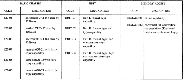
[image:9.789.105.745.81.498.2]Table 1. Display and Edit Options
BASIC CHASSIS EDIT MEMORY ACCESS
CODE DESCRIPTION CODE DESCRIPTION CODE DESCRIPTION
--620-01 horizontal CRT (64 char by EDIT-Ol Edit I, format type MEMACC-Ol no tab capability
32 lines) capability
MEMACC-02 horizontal tab and vertical 620·02 vertical CRT (52 char by EDIT-02 Edit II, format type and tab capability (Keyboard
40 lines) type capability must also contain tab keys)
620-03 horizontal CRT (84 char by EDIT-03 Edit II, format type, and 32 lines) conversation type
capability 620-04 same as 620-01 with
hard-copy capability EDIT-04 Edit II, format type, type and conversation type 620-05 same as 620-02 with hard- capability
copy capability
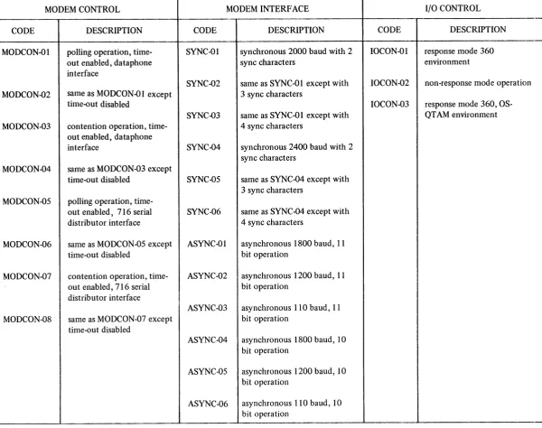
[image:10.789.80.694.119.388.2]Table 2. Input/Output Options
"-MODEM CONTROL MODEM INTERFACE I/O CONTROL
" "
-CODE DESCRIPTION CODE DESCRIPTION CODE DESCRIPTION
MODCON-Ol polling operation, time- SYNC-Ol synchronous 2000 baud with 2 10CON-01 response mode 360 out enabled, dataphone sync characters environment interface
SYNC-02 same as SYNC-Ol except with IOCON-02 non-response mode operation MODCON-02 same as MODCON-Ol except 3 sync characters
time-out disabled IOCON-03 response mode 360, OS-SYNC-03 same as SYNC-Ol except with QTAM environment MODCON-03 contention operation, time- 4 sync characters
out enabled, dataphone
interface SYNC-04 synchronous 2400 baud with 2 sync characters
MODCON-04 same as MODCON-03 except
time-out disabled SYNC-OS same as SYNC-04 except with
00 3 sync characters
MODCON-OS polling operation,
time-out enabled, 716 serial SYNC-06 same as SYNC-04 except with distributor interface 4 sync characters
MODCON-06 same as MODCON-OS except ASYNC-Ol asynchronous 1800 baud, 11 time-out disabled bit operation
MODCON-07 contention operation, time- ASYNC-02 asynchronous 1200 baud, 11 out enabled, 716 serial bit operation
distributor interface
ASYNC-03 asynchronous 110 baud, 11 MODCON-08 same as MODCON-07 except bit operation
time-out disabled
ASYNC-04 asynchronous 1800 baud, 10 bit operation
ASYNC-OS asynchronous 1200 baud, 10 bit operation
[image:11.789.104.705.84.558.2]characteristics
I/O functions
character presentation
FUNCTIONAL DESCRIPTION
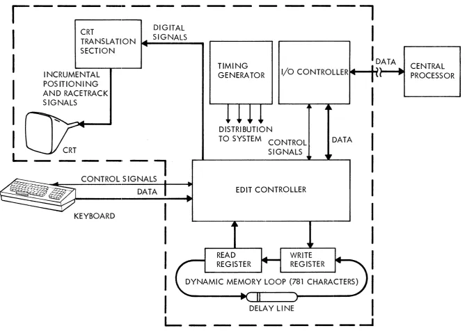
GENERAL. The 620 Data Display System, illustrated by the Simplified Functional Block Diagram, Figure 4, has the characteristics of a special purpose computer that is controlled by a hardware program, with provisions for visual read-out of stored data. The hardware provides the system with the ability to recognize ASCII coded characters and to manipulate and transfer memory data according to the intended action of each character and the edit mode being employed. The edit controller, for example, writes data from the keyboard or central processor into the dynamic memory in the correct location, then controls the editing or augmenting of the stored data with new inputs from the keyboard or central processor. The edit controller also controls the copying of stored data by the central processor when the send command is supplied from the keyboard, by providing only the memory data allowed by the current edit mode.
The I/O controller, with its built-in program, recognizes its own address, generates the appropriate address sequence data and responses, checks parity of each received character and message, adds the correct parity bit to each transmitted character and accumulates a longitudinal redundancy check character which is used by the central processor to check parity of the message sent by the 620 System.
The CRT (cathode ray tube) translation section presents a visual read-out of the data circulating in the dynamic memory loop. This displayed data consists of alphanumeric characters which are English language symbols written on the screen and control characters (carriage return, vertical tab, horizontal tab and memory start) which effect the arrangement of the alphanumeric characters, but are not displayed.
KEYBOARD. The keyboard is the input interface between the operator and the 620 Data Display System. Its appearance is similar to that of a standard typewriter, but with the additional grouping of control keys and a group of indicator lamps.
The keyboard contains the electroni<;s that convert operator-keyed inputs into seven-bit binary-coded, data word outputs. The electronics consists of key microswitches, a matrix encoder, a seven-bit storage register, and the data-ready logic that coordinates the control and operations of the keyboard. The relationship between each key and the displayed data is discussed in detail
in the 620 Data Display System Operator's Handbook published by Sanders Associates, Inc.
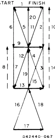
CRT TRANSLATION SECTION. The CRT translation section contains the electronics to convert digital information from the edit controller to a visual screen presentation. Format electronics increment the electron beam across the face of the cathode ray tube in a left-to-right, top-to-bottom presentation. At each character position, write electronics cause the "racetrack" pattern shown in Figure 5 to be traced on the screen and simultaneously causes the correct strokes to be unblanked, allowing alphanumerics to be fluorescent on the screen.
,---CRT
DIGITAL
TRA NS LA TI 0 N .... _S _I
G_N_A_L_S_ ...
SECTION
-I
I
INCRUMENTAL
POS ITIONI NG
AND RACETRACK
SIGNALS
TIMING
GENERATOR
I
D,A TA... CENTRAL
I/O
CONTROLLERte-....-t~,
... PROCESSOR
I
I
I
~
=T:'SI::~~
KEYBOARD
I
I
I
I
I
L
DISTRIBUTION
TO SYSTEM CONTROL
SIGNALS
EDIT CONTROLLER
READ
REGISTER
WRITE
REGISTER
DATA
I
I
I
I
I
I
I
I
DYNAMIC MEMORY LOOP (781 CHARACTERS)
I
DELAY LINE
I
- -
- - -
_...J
[image:13.789.50.722.58.537.2]memory capacity
code conversation
START FINISH
t
6
1
10I
t
f
I
81
114
I
II
042440-067
Figure 5. Racetrack Pattern
DYNAMIC MEMORY. The dynamic memory loop provides the principal storage of information in the 620 System. It may receive data inputs from the keyboard or central processor through the write register. A continual readout of stored data is accomplished by the read register. The memory loop, consisting of the read/write registers and the delay line provides storage for 781 eight bit characters. One memory position is reserved for the memory start (MS) character which acts as an index for the edit controller. Data is loaded into memory by the edit controller in a three character interlace method providing 21.3 microseconds between each successively displayed character.
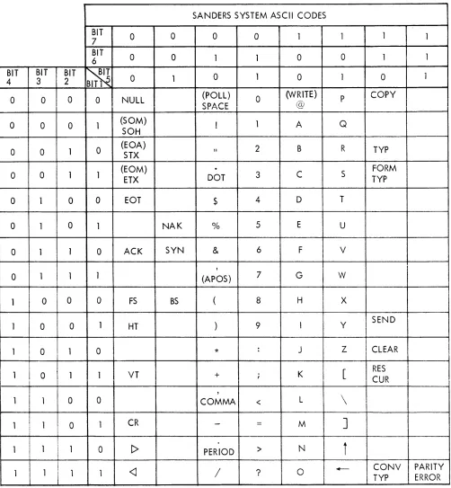
620 SYSTEM CODE SET. The 7 -bit ASCII (American Standard Code for Information Interchange) code set is used internally in 620 terminal and for communication between the data transmission device and the 620 I/O section. The code set is illustrated by Figure 6.
Data transmitted or received over the computer channel is normally an eight bit code which is the seven bit code modified by adding an x-bit between the fifth and sixth bit of the illustrated code (76x54321). The x-bit is always the same as bit 7. The seven bit code for the letter s, for example, is 1010011. When converted to eight bit code, s becomes 10110011.
[image:14.612.266.363.112.352.2]SANDERS SYSTEM ASCII CODES
BIT
0 0 0 0 1 1 1
7 1
BIT
0 0 1 0 0
6 1 1 1
BIT BIT BIT
~
0 14 3 2 BIT1 5 0 1 0 1 0 1
0 0 0 0 NULL (POLL) 0 (VVRlTE) P COpy
CDArc: @
oJl T"""\'-"~
0 0 0 1 (SOM) ! 1 A Q
SOH
0 0 1 0 (EOA)
STX \I 2 B R TYP
I
(EOM)
.
FORM0 0 1 1
ETX DOT 3 C S TYP
I
0 1 0 0 EOT$
4 D T0 1 0 1 NAK % 5 E U
0 1 1 0 ACK SYN & 6 F V
,
0 1 1 1 (APOS) 7 G W
I
1 0 0 0 FS BS ( 8 H X
1 0 0 1 HT ) 9 I Y SEND
1 0 1 0
*
: J Z CLEARI
I1 0 1 1 VT + ; K
[
RESI
I CUR
,
1 1 0 0 COMMA < L
\
1 1 0 1 CR
-
=
MI
]
1 1 1 0 [> PERIOD
>
NI
ii
1 1 1 1
<J
/
? 0 +-- CONV PARITYTYP ERROR
Figure 6. 620 System Code Set
[image:15.612.46.548.106.649.2]communication control characters
modes of entry
format type mode
type mode
conversation type
Six of the characters shown in Figure 6 are communication control characters. These characters are reserved to maintain intelligence in the flow of data traffic. The definitions of these characters, as they are interpreted by the 620 System I/O or the computer I/O, are given below.
SOH (Start of Heading). A character used at the beginning of a sequence of characters which constitute a 620 (machin~) address.
STX (Start of Text). A character which precedes a message. The message is terminated by ETX.
ETX (End of Text). A character that terminals a message that has been preceded with STX. EOT (End of Transmission). A character that indicates the end of a transmission. EOT is also sent by the 620 System if there is no message in a computer poll.
ACK (Acknowledge). A character transmitted or received as an affirmative response to the sender, usually indicating no parity errors in the transmission. ACK is used in 620 System response mode data transfer.
NAK (Negative Acknowledge). A character transmitted or received as a negative response to the sender, usually indicating a parity error. NAK is a command to the 620 System to retransmit in response mode data transfer.
EDIT CONTROLLER. The 620 System can be operated in any of three modes of data entry. The three modes are defined as: Format Type, Type and Conversation Type. The modes of data entry available are determined by the edit module used and the options selected with the module. The basic 620 System is supplied with the Edit I Module which is capable of Format Type Mode only. As an option, the Edit II Module can be supplied, equipped for Format Type, Type and Conversation Type modes of data entry. This discussion assumes that an Edit II Module with all optional modes is used.
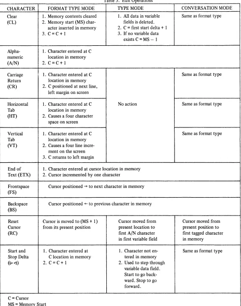
The 620 System is automatically placed in Format Type Mode at initial system turn-on or when the hard-copy key is depressed and remains in this mode at all times until either a Type Mode character or a Conversation Type Mode character is entered into the edit controller from the keyboard or the central processor, or the hard-copy busy signal is dropped. In Format Type Mode, data can be entered on the screen in a top-to-bottom, left-to-right format. The 620 System can be returned to the Format Type Mode from any other mode by entering the Format Type character. The edit operations are tabulated in table 3 for all three modes.
Type Mode enables the 620 System to operate in a two block format. The fixed block is established in Format Type Mode and the variable data is entered in Type Mode. In Type Mode, data entry and cursor movement is restricted to the variable data fields. A variable field is defined as the data between a Start Delta character and a Stop Delta character. Any number of variable fields may be established. The system is placed in the Type Mode when the Type Mode character is entered into the edit controller from the keyboard or the central processor and remains in this mode until either the Format Type or the Conversation Type Mode character is entered. Upon receipt of the Type Mode character, the cursor is moved to the first character position of the first variable field in memory. If no variable fields have been established in memory, the cursor will stop at the MS-l position which is the last position in memory.
Table 3. Edit Operations
CHARACTER FORMAT TYPE MODE TYPE MODE CONVERSATION MODE Clear 1. Memory contents cleared 1. All data in variable Same as format type (CL) 2. Memory start (MS) char- fields is deleted.
acter inserted in memory 2. C
=
first start delta+
1 3. C=
C+
1 3. If no variable dataexists C
=
MS - 1Alpha- 1. Character entered at C numeric location in memory
(A/N) 2. C
=
C+
1Carriage 1. Character entered at C Same as format type Return location in memory
(CR) 2. C positioned at next line, left margin on screen
Horizontal 1. Character entered at C No action Same as format type Tab location in memory
(HT) 2. Causes a four character space on screen
Vertical 1. Character entered at C Same as format type Tab location in memory
(VT) 2. Causes a four line incre-ment on the screen 3. C returns to left margin
End of 1. Character entered at cursor location in memory Text (ETX) 2. Cursor incremented by one character
Frontspace Cursor positioned ~ to next character in memory (FS)
Backspace Cursor positioned ~ to previous character in memory (BS)
Reset Cursor is moved to (MS
+
1) Cursor moved from Cursor moved from Cursor from its present position present location to present position to (RC) first AIN character first tagged characterin first variable field in memory
Start and 1. Character entered at 1. Character not en- Same as format type Stop Delta C location in memory tered in memory
(1)<1) 2. C
=
C+
1 2. Used to step through variable data field. Start to go back-ward. Stop to go forward.C
=
CursorI
MS
=
Memory Start [image:17.612.28.518.84.706.2]tagging
stop and start deltas
cursor movement only
hard-copy routine
The action of Conversation Type Mode is accomplished by adding a one bit to each character (tagging) as it is entered into memory. Both keyboard data and central processor data are tagged. Each message segment is terminated with the ETX (end of text) character. During the send routine, only tagged memory characters up to ETX are sent to central processor. Upon receipt of ACK from the central processor, indicating the message segment was received without errors, all the tag bits in memory are cleared, the ETX is replaced with a CR (carriage return) in memory by the edit logic and the cursor is positioned at the CR+ 1 location. If there were errors in the message segment received by the central processor, it sends NAK to the 620 System and the message segment is retransmitted. The 620 System will repeatedly transmit the tagged characters each time an NAK is received until an ACK is received. During a write routine, each character from the central processor is tagged when entered into memory. If the 620 System receives the message segment successfully with no LRC or VRC errors, the I/O section will send ACK to the central processor and the edit logic will clear the tag bits in memory and change the ETX to CR. If an error is detected in the received message segment, the I/O will send NAK to the central processor, the cursor will be positioned at the first tagged character and the edit logic will erase all tagged memory characters in anticipation of a retransmission from the central processor.
The Stop and Start Delta characters are entered into memory in Format Type Mode to establish the parameters of the fixed and variable fields and are treated as alphanumerics in this mode. In Type Mode these characters are not entered into memory, but are used to accomplish cursor movement between the variable fields by the operator. (See Operator's Handbook.) Also, in Type Mode, only data inclosed by the Start Delta and the Stop Delta will be transmitted to the central processor in a send operation.
The following operational action characters accomplish cursor movement only and are not entered into memory from the keyboard in any mode: reset cursor, frontspace and backspace. The send character is not entered into memory, but accomplishes cursor movement and starts the 620 System into an output routine. The cursor is positioned at the first character to be transmitted and the I/O Controller is signaled.
HARD-COPY OPTION. The Hard-Copy I Option is utilized when it is desirable to produce a permanent record of data displayed on the 620 System terminal screen. A Model ASA 33 or a Model ASA 35 Teletypewriter may be used to copy screen data. The Hard-Copy I Option consists of the following components:
Hard-Copy Buffer I plug-in module Printer
Hard-Copy data transmission cable (1000 feet maximum) Modified Keyboard (COpy key added)
code conversions
hard-copy modes
copy mode I
copy mode II
synchronous operation
asynchronous operation
The Hard-Copy Buffer I makes the following code conversions:
1. Start Delta is converted to a space code. 2. Stop Delta is converted to a space code.
3. Horizontal Tab is converted to four space codes.
4. Vertical Tab is converted to one carriage return and four line feed codes. 5. Carriage Return is converted to a carriage return plus a line feed code.
A carriage return and a line feed are automatically sent to the printer by the Hard-Copy Buffer I module at the start of a copy routine.
There are two modes of 620 System hard-copy routines. Copy Mode I copies all of the data on the screen, performing the code conversions discussed previously. Copy Mode II copies only the variable field data. Copy Mode I is accomplished when the 620 System is operating in the Format Type Mode or Conversation Type Mode. The system Type Mode initiates Copy Mode II.
Copy Mode I copies all data sequentially received from the 620 System with the stated code conversations.
Copy Mode II copies all data sequentially received from the 620 System, making the previously stated code conversions and the following additional code conversions:
1. All alphanumeric data between Memory Start and the first Start Delta are converted to space codes.
2. AllalphanumericdatabetweenaStopDelta and a Start Delta are converted to space codes. 3. All alphanumeric data between the last Stop Delta and Memory Start are converted to
space codes.
4. Nulls received between Start and Stop Deltas are converted to space codes.
I/O CONTROLLER. The I/O (Input/Output) Controller is the interface between the computer-and data transmission equipment-and the edit and display sections of the 620 System. Many interface options are available and are tabulated in the "Configuration" section of this Manual. The I/O functional characteristics are discussed here. By the selection of optional modem interface modules, the 620 System may be operated either synchronously or asynchronously with the transmission equipment.
In synchronous operation, eight-bit data bytes are communicated containing seven ASCII coded data bits and one parity bit. Vertical parity in synchronous operation is odd. Each byte is successively transmitted with no breaks or time between the last bit of the leading character and the first bit of the next character. If a break in data is necessary, the computer must send null characters or synchronization will be lost. Each message sequence from the computer in synchronous operation must be preceded by two or more ASCII Sync characters. In 620 to computer transmission, each message sequence will be preceded by 2, 3 or 4 Sync characters as determined by selected jumper options on the synchronous module. Transmit and receive clocks are supplied by the modem and communication is at a rate of 2000 or 2400 baud.
When asynchronous operation is used, ten or eleven bit character bytes are communicated which are made up of seven ASCII character bits, a start bit, a vertical parity bit and one or two stop bits. Synchronization is achieved using the start and stop bits of each character. For this reason asynchronous communication is also known as "stop-start" communication, and there is no timing
transfer modes
OPERATION
WRITE
POLL
CONTENTION
error checks
restrictions between successive bytes. Vertical parity is even. In asynchronous operation, the 620 System uses an internal clock for timing of transmitted and received data. Baud rates of 110, 1200, or 1800 can be selected using optional jumper connections on the asynchronous module.
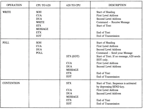
Either the response mode or the non-response mode of data transfer is available when using the 620 System. The response mode requires the use of a longitudinal redundancy check and acknowledgments. The non-response mode does not utilize longitudinal redundancy checking. The difference between the two modes can be easily seen in the communication sequences, tables 4 and 5.
Table 4. Non-response Mode Communication Sequences
CPU TO 620 620 TO CPU DESCRIPTION
SOH Start of Heading
CUA First Level Address
DUA Second Level Address
WRITE Command - Receive Message
STX Start of Text
MESSAGE
ETX End of Text
EOT End of Transmission
SOH Start of Heading
CUA First Level Address
DUA Second Level Address
POLL Command - Send your Message
STX(EOT) Start of Text. If no message, 620 sends EOT only.
CUA First Level Address DUA Second Level Address MESSAGE
ETX End of Text EOT End of Transmission
STX Start of Text. Sequence is activated by depressing SEND key.
CUA First Level Address DUA Second Level Address MESSAGE
ETX End of Text EOT End of Transmission
[image:20.612.58.562.237.626.2]Table S. Response Mode Communication Sequences
OPERATION CPU TO 620 620 TO CPU DESCRIPTION
WRITE SOH Start of Heading
CUA First Level Address
DUA Second Level Address
WRITE Command - Receive Message
ACK(NAK) Proceed - If there is an address (EOT) sequence parity error, 620 sends NAK.
If' J... ... rl "',.,. .... " ~" ~~ ... "''''''''''' t:::"ltl "",~rl"
.1..1. .I.I.U.lU-""VP'y .l.:J ll.l. l'J.V\,.I''''.Ji.:J, V k V ~\.II1U.Ji
EOT as busy signal.
STX Start of Text
MESSAGE
ETX End of Text
LRC Longitudinal Parity Character
ACK(NAK) Proceed - If an error is declared by the 620, it sends NAK as a request to re-transmit message.
EOT End of Transmission
i i
POLL SOH
I
Start of HeadingCUA I First Level Address
DUA
I
Second Level AddressPOLL Command - Send your Message
I
STX (EOT) Start of Text. If 620 has no message, it sends EOT only.
!
CUA First Level AddressI
I
DUA Second Level Addressi
MESSAGEI
ETX End of TextI
I
LRC Longitudinal Parity Character ACK(NAK) Proceed - If there is a parity error,
!
CPU sends NAK and 620 re-transmits
I
I
from STX.
I
EOT End of Transmission
CONTENTION STX Start of Text. Sequence is activated
by depressing SEND key. CUA First Level Address DUA Second Level Address MESSAGE
ETX End of Text
LRC Longitudinal Parity Character ACK (NAK) Proceed - If there is a parity error,
CPU sends NAK and 620 re-transmits from STX.
EOT End of Transmission
LRC
I/O operations
address sequence
CUA
DUA
When in the response mode, the I/O accumulates the LRC (Longitudinal Redundancy Check) character which is the MOD 2 sum of all the ASCII coded characters and the parity bits of all the message bytes after STX (Start of Text) and including the ETX (End of Text) character. In a response mode poll operation (see definition below), the I/O sends the LRC character to the computer after ETX. In a write operation, the I/O accumulates an LRC character, just as in a poll operation, but after ETX the computer sent LRC is compared to the accumulated character for parity. Incorrect parity in either a poll or write operation results in a negative acknowledgment (NAK) which is considered a request to retransmit the message. If the 620 I/O receives NAK, it will automatically send tht: message again. An ACK indicates that the message was received correctly.
In both the response and non-response modes, the three I/O operations that are performed are write, poll and contention. Contention operation is a 620 option and is selected by a jumper connection on the modem control module. The poll operation is a request by the computer to the 620 System to send. Poll and contention are similar except that in contention operation the 620 System will send without a poll command from the computer. In both cases the operator of the 620 System must have depressed the SEND key. The write operation is the sending of data from the computer to the 620 System.
In both data transfer modes, a poll or write operation must be initiated by the computer in a four character command sequence as follows:
1. SOH (start of heading) 2. CUA (first level address)
3. DUA (second level address) X'09' 4. Command (write or poll)
The CUA address may be any of the characters in the 620 System code set except the 16 reserved codes listed below. Note that these reserved codes are expressed in 8 bit hexadecimal code.
NULL X'OO' X'll'
SOH X'01' X'12'
STX X'02' X'13'
EXT X'03' X'14'
EOT X'04' NAK X'1S'
X'OS' SYNC X'16'
ACK X'06' POLL X'40'
X'10' WRITE X'AO'
Ii
I
this discussion is for programmers
use of the formulas
TIMING CONSIDERATIONS
GENERAL. Timing considerations within the 620 System are mode dependent and thus will be discussed on an operating mode basis. The memory access time of the 620 is 5.55 milliseconds and the majority of functions can be completed in one memory cycle time. Some control functions will require additional time to complete their operation in certain modes and it will therefore be necessary to program null characters. The number of null characters required is a function of the mode (asynchronous or synchronous) and transmission rate (110, 1000, 1200, 1800,2000,2400 baud) of data. The transmission time taken by the number of null characters used must equal the fIxed response time required to complete the desired 620 control operation. To facilitate the editing operations required for null character insertion in outgoing messages, use of the Sanders-furnished EDITMOVE macro-instruction is recommended.
The formulas presented here will enable the programmer to determine the worst case number of nulls to insert in a message for each control character. In some instances it will be noted that the number of nulls needed must be partially estimated due to diffIculty in predicting the contents of the 620's memory.
NULL FORMULAS. Unless otherwise stated, the quantity of nulls represented should be inserted
following the given character in the message.
a. Determine the value of f from Table 6 applicable to the current transmission mode and transmission rate.
b. f represents a number dependent on transmission characteristics which is then used in conjunction with the formulas to determine the number of nulls to be inserted. Where multiples of f are indicated, round down the final sum or product only. Otherwise, f may always be rounded down to a whole number. (e.g., if the fInal sum or product of a calculation equals 6.86 nulls, this may be rounded down to 6 nUlls.) The notation (X) Y means "Y in mode X" where X is a mode change character (i.e., FT, TP, or CT). c. To determine the fIxed response time required for any of the listed 620 control operations which require nulls, set f equal to 5.55 milliseconds. Thus (FT) BS = f
=
5.55 milliseconds.FORMAT TYPE MODE NULLS. The following timing constraints are placed on programming the 620 in Format Type (FT) mode:
TYPE MODE NULLS. The following timing constraints are placed on 620 programming when in Type (TP) mode:
(TP)CL
=
5 f after each CL in TP mode(TP)A/N = no null requirement except when the A/N entry is made in a location immediately preceding a Stop Delta (<I) character. In this case, the cursor is automatically advanced to the beginning to the next variable field, and the null requirement equals f/260 X (number of characters through which cursor must advance).
(TP)CR = no operation in TP mode (TP)HT = no operation in TP mode
(TP)VT
=
no onPT::Itlon ln TP mocip,--/. - --- -r-- --- --
---(TP) I> and <I : The timing requirements with respect to Start and Stop Delta are functions of the format already established in memory.
(fP)1> = ffor each character through which the cursor must backspace. The use of this code requires that a variable number of nulls be programmed depending upon the number of positions in memory through which the cursor is automatically backspaced. The exact number of backspaces is a function of the present cursor location and the location of the preceding Stop Delta (<I) character in memory.
(TP) <I
=
f/260 X (number of characters through which cursor must advance). The use of this code causes an automatic forward space of the cursor which can be accomplished in 21.3 microseconds per character position. The exact number of forward spaces is a function of the present cursor location and the location of the following Start Delta (I> ) character in memory.(fP)ETX
=
no null requirement(fP)RC = f/260 X (number of characters through which cursor must advance); the total number of characters is measured from MS (Memory Start) to the first Start Delta (I»
character in memory.
(TP)FS = no null requirement except when the FS entry is made in a location immediately preceding a Stop Delta
«I)
character. In this case, the cursor is automatically advanced to the beginning of the next variable field, and the null requirement equals f/260 X (number of characters through which cursor must advance).(fP)BS
=
f after each BS in TP mode except when the cursor is located immediately following a Start Delta (I» character. In this case, the null requirement equals f for each character through which the cursor must backspace to get to the last character of the preceding variable field, as in the operation of (TP) I> above.(TP)SP
=
no null requirementCONVERSATION TYPE MODE NULLS. The following timing constraints are placed on 620 programming when in Conversation Type (CT) mode:
(CT)CL
=
no null requirement (CT)A/N = no null requirement (CT)CR = no null requirement (CT)HT=
no null requirement (CT)VT=
no null requirement (CT) I> and <I=
no null requirementTRANSMISSION RATE 2400 2000 1800 1200 1000 110
(CT)RC
=
f/260 X (number of characters through which cursor must advance); the total number of characters is measured from MS (Memory Start) to the first character in the current message.(CT)FS
=
no null requirement (CT)BS=
f after each BS in CT mode (CT)SP=
no null requirementTable 6. fValues
TRANSMISSION MODE
SYNCHRONOUS ASYNCHRONOUS 8-BIT 10-BIT ll-BIT
1.67 1.33 1.21
1.39 1.11 1.01
N/A 1.00 0.908
[image:26.612.107.495.222.345.2]PROGRAMMING CONSIDERATIONS FOR USE OF 620 WITH IBM SYSTEM/360
This discussion is for programmers
DCB
non-mixed environment
GENERAL. IBM provides a read/write routine common to all supported TP devices plus a number of Device Dependent Modules (DDM's), each of which consists of a tabular set of constants uniquely defined for a supported device. At OPEN time, a logical connection is established between the appropriate DDM, the I/O control block (DCB, DTFQT, or DTFBT), and the common read/write routine. Subsequent I/O requests, via the language (i.e., macro-instruction) facilities of the IBM access method used, cause the common read/write routine to generate channel programs appropriate to the device to be communicated with by using the reference information tabulated in the linked DDM.
The 620 Display Terminal becomes fully supported under any IBM access method in this category by simply using the appropriate Sanders-furnished Device Dependent Module(s). The Sanders-furnished DDM(s) may be incorporated and put to use in a number of ways. For example, in the event that the only display terminal type to be used in a particular installation is the Sanders 620 Data Display System, it is only necessary to replace the DDM intended for the IBM 2260 with the Sanders-furnished DDM for the 620. The full facilities of the access method now become available and can be used exactly as described in the appropriate IBM publication.
OS BTAM-(REMOTE CONNECTION). The following discussion describes the steps one must follow to use the 620 Data Display System with OS BT AM.
The problem programmer must provide a Data Control Block (DCB) for each line group to be used. He must initialize each DCB by using the IBM OPEN macro-instruction and should insure that each OPEN operation was successful. After execution of the OPEN macro-instruction, bit 3 of the DCBOFLGS field in the DCB, dcbaddr
+
48, is set to 1 if the Data Control Block has been opened successfully and is set to 0 if the DCB has not been opened successfully. If the user has not replaced the catalogued IBM 2260 DDM (IGG019M3) in SYSl.SVCLIB, he then must issue the DOPEN macro-instruction (provided by Sanders) to set up the necessary linkages between OS BTAM, one of the Sander's DDM's, and the DEB's in his program. (See Sanders First-LevelSupport Manual for a detailed description of the TABLES macro-instruction.) In addition to the
normal alphanumerics, these tables contain the special edit and function characters unique to Sanders Displays.
OS QT AM-(REMOTE CONNECTION). To use the 620 Display System with OS QTAM, the user should do the following:
a. Translate the incoming and outgoing messages using the Sanders-supplied TABLES macro-instruction or the IBM supplied TRANS macro-instruction. For detailed descriptions, see the Sanders First Level Support Manual for the TABLES macro-instruction and the IBM publication C30-2003 for the TRANS macro-instruction.
b. Ensure that when the BT AM read/write routine is invoked by QTAM for an I/O operation the routine will construct channel programs that are compatible with the Sanders 620 Display System. There are two methods to accomplish this.
Method I:
mixed environment
NAME OPENIO
auto linking
Method 2:
If the user wishes to retain the capability for operating IBM 2260's or he wishes to operate Sanders 720 and 620 Displays, he must first link-edit the Sanders DDM into SYSI. LINKLIB. Secondly, he must employ the DOPEN macro-instruction to perform the necessary DCB initialization. Finally, he must furnish the linkage editor control statements to include the modules in his program.
OPERATION OPERAND 72
OPEN (DISK, (INOUT), X
LINE2260, (INOUT), X
LINE620, (INOUT, X
IDLE)
DOPEN LINE620, X
DEVTYPE
=
(620, XQTAM)
LA 7, LINE620
STARTLN (7)
Note that using the IDLE parameter in the "options" field associated with the Sanders display line group defers polling of the line group to allow DCB initialization to be performed by DOPEN. Even if IGG019NR is replaced, the IDLE option should be used.
Subsequently, polling is initiated by STARTLN.
To obtain automatic linking of the DOPENed DDM's ensure that the NCAL option is not specified and that the JCL for the linkage editor includes the following DD card:
NAME OPERATION OPERAND
//SYSLIB DD DSNAME
=
name* , XDISP
=
OLD*name = the name of the data set containing the DDM.
DOS BT AM-(REMOTE CONNECTION). To employ the 620 Display System in conjunction with DOS BTAM, the user must do the following:
a. Use the Sanders - supplied TABLES macro-instruction to convert incoming and outgoing messages to the appropriate codes.
b. Ensure that the DOS BT AM control program will access the appropriate Sanders Device Dependent Module (DDM) for contracting channel programs by using the Sanders supplied DOPEN macro-instruction.
c. Also using the DOPEN macro-instruction, ensure that DTFBT's which refer to Sanders Display line groups have been properly initialized.
DOS QTAM-(REMOTE CONNECTION). To use the Sanders 620 Display System with DOS QTAM, the user should do the following:
a. With the Sanders-supplied TABLES macro-instruction, convert incoming and outgoing messages to the appropriate codes.
non-mixed environment
mixed environment
b. Ensure that the DOS QT AM control program will access the appropriate Sanders Device Dependent Module (DDM) for constructing channel programs using the Sanders DOPEN macro-instruction. There are two methods available to accomplish this.
Method 1:
If the user is operating in a non-mixed environment, i.e., is using only Sanders 620 Displays, he may replace the IBM 2260 DDM for QT AM with the appropriate Sanders-supplied DDM in the relocatable library.
Method 2:
If the user wishes to retain capability for operating IBM 2260's or he wishes to operate both Sanders 620 and 720 Displays, he must employ the DOPEN macro with DEVTYPE
=
((620 or 720), Q(TAM)), to perform the necessary DTFQT initialization.DEVICE DEPENDENT MODULE (DDM) DESCRIPTION. A number of Device Dependent Modules have been designed by Sanders to provide I/O processing compatibility between
as
BTAM/QTAM, DOS BTAM/QTAM, and Sanders Display Systems in a remote environment.Detailed message structures for remote operation are shown here.
Messages received from a 620 terminal by the CPU have the following format:
STX CUA X'09'
First Text Character
Last Text Character
ETX LRC
Start of Text. Control Unit Address. 620 Display Address.
Variable length message from 620 memory.
End of Text
Longitudinal Redundancy Character.
NOTE
The LRC character is sent by the 620 system but is not transferred into main storage.
Messages sent to a 620 terminal from the CPU have the following format:
STX
Ff
Start of Text.
First Text Character
Last Text Character
ETX LRC
Variable length message from user's I/O area.
End of Text
Longitudinal Redundancy Character
NOTE
The LRC character is generated by the transmission control unit-no user action is required.
ACCESS-METHOD DEPENDENT INFORMATION
ACCESS METHOD MESSAGES FROM 620 TO CPU MESSAGES TO 620 FROM CPU
OSBTAM
OSQTAM DOSBTAM
DOSQTAM
using a DDM
STX appears in first-character STX and FT on output are provided position of user's area followed by the DDM. The user can start his by CUA, X'09' (display address), message in position one of his buffer. and message text; terminated by If a mode other than FT is desired, an ETX. the user can start with another
mode-change character. Same as OS BT AM Same as OS BT AM
Same as OS BT AM Under DOS BT AM the user must provide his own STX character and FT or other mode-change character. The message must terminate with an ETX.
Same as OS BT AM Same as OS BT AM
A user may obtain the service of a particular DDM in one of two ways. He may replace the appropriate IBM 2260 DDM with the desired Sanders DDM and rename it with the name of the 2260 DDM, or he may use the Sanders DOPEN macro-instruction. The DEVTYPE parameters of the DOPEN macro-instruction should be coded as follows to obtain the services of a particular DDM:
DEVTYPE
=
(model-number, access-method)MODEL-NUMBER 720 or 620 720 or 620
OS-DDM's (BT AM) DDMOSNOI (QTAM) DDMOSQOl
28
ACCESS-METHOD BTAM
QTAM
EDITMOVE
MESSAGE PROCESSING MACROS. A number of message processing macro-instructions have been designed by Sanders to assist the user of Sanders Data Display Systems in handling his message processing functions. Of particular interest to the 620 user are two macros named EDITMOVE and TABLES.
dataset interface
OSBTAMQTAM
NOTE
As Required For 731 For 620 Line Groups*
INTERFACE REQUIREMENTS AND CHARACTERISTICS
HARDWARE INTERF ACE. The 620 Data Display System meets the requirements of EIA
Standard, RS-232-B. The 620 contains selectable interfaces consisting of jumper wire patching on the Modem Control Module enabling it to interface with either a dataset or the Sanders 716 Serial Distributor.
The 620 Data Display System will interface with the following A T & T datasets:
a. Model103A b. Model103F c. Model 202C d. Model 202D e. Model201A f. Model201B
The 620 may also be interfaced with the Sanders 716 Serial Distributor. The 716 Serial Distributor enables the 620 to be located up to 1000 feet away from the dataset and allows mUltiple (up to sixteen) 620's to be connected to a single dataset. The primary difference in the 716 interface is that the the signal levels are +5 V and 0 V instead of the dataset levels of ±lS V. When the 716 Serial Distributor is used, the Data Terminal Ready signal originatesm the Serial Distributor and is not individually carried from each 620 to the Serial Distributor.
SOFTWARE INTERFACE WITH IBM SYSTEM/360. The Sanders 620 Data Display System will interface with the IBM System/360 computer under the control of either the OS or DOS operating System. BT AM or QT AM access methods may be utilized.
Under OS the system generation macro-instructions tabulated below should be completed for utilization of the 620 System with BTAM and QTAM.
NAME OPERATION OPERAND
DATAMGT TE LCM LIB
IOCONTRL UNIT
=
2701, ADDRESS=
XXIODEVICE UNIT
=
2260, ADAPTER=
IBM 3, XMODEL
=
1, ADDRESS=
XXYIODEVICE UNIT
=
2260, ADAPTER=
IBM 3, XMODEL
=
1, ADDRESS=
XXY*(Up to eight 620 line groups per 731 Data Communications Buffer)
XX
=
channel number and channel position (731)Y = 731-line position (for 620 display terminal or 716 serial distributor)
NAME OPERATION OPERAND
DVCGEN CHUN =: X' cur, DVCTYp:: 2701
c = 0 for Multiplexer Channel
u
=
731 Data Communications Buffer number (O-F)1
=
731 line number (for 620 display terminal or serial distributor)Caution
In choosing line address fordisplay devices, care must be taken to select an address
Ulh11"h 10;1 '.ll"l"pnt'.lhlp to thp I"h'.lnnpl An .. ~~~-~~ ~~ ----r ~-~~- ~- .~~- -~.-~.~.-~. .~.
IBM Representative should be consulted to determine which addresses have been implemented on the channel the user wishes to use for the I/O connection.
T
18.12cables
INSTALLATION PLANNING DATA
GENERAL. When planning the installation of the 620 Data Display System, the planner should be familiar with the information presented in the "Configuration" section of this manual. The publication entitled Sanders Data Communications Configurator may also be used as a reference. All of the display, edit and input/output options are contained within the terminal cabinet.
PHYSICAL SPECIFICATIONS. The 620 Data Display System is a desk-top terminal. The keyboard may be attached directly to the terminal or remotely located with 10 feet of cable. The 620 terminal weighs 50 pounds. Dimensions are shown in Figure 7.
1
13.
64
1
1 4 - - - -26.40 - - - . ,
DIMENSIONS IN INCHES
F72508
Figure 7. 620 Terminal Dimensions
A standard 25-pin dataset connector is mounted on the rear of the base along with an AC power connector and a two-terminal printer connection strip. The printer terminals are active only when the optional hard-copy buffer module is contained within the display terminal cabinet.
A seven-foot three-prong AC power cord and a ten-foot dataset cable-connector assembly is provided with each 620 Data Display System terminal. The installation site should be selected or arranged so that an AC power outlet and the dataset are within reach of the cables provided.
AC POWER. The 620 operates directly from standard wall outlets that provide 117 V AC ± 10 percent, 48 to 62 Hertz power. Dissipation is 200 watts.
AMBIENCE. Normal performance is achieved under the following conditions:
Temperature: Humidity:
Barometric Pressure:
*no condensation is allowed.
Operating +60°F to +90°F 10 to 90 Percent* up to 10,000 ft.
[image:36.612.298.541.229.396.2]APPENDIX A
DISPLAY TERMINAL
The Display Terminal is complete within the cabinet and base assemblies. When the keyboard is connected, only a dataphone modem is required for data entry or retrieval with a central computer. The modular construction allows access to all components for maintenance with a minimum amount of time and effort.
INPUT POWER CRT SIZE DEFLECTION SPOT SIZE BRIGHTNESS PHOSPHOR FRAME RATE CHARACTER HEIGHT CHARACTER WIDTH CHARACTERS/LINE
NUMBER OF LINES
NUMBER OF CHARACTERS CHARACTER SPACING LINE SPACING
INTERNAL CLOCK RATE CHARACTER WRITE TIME CHARACTER TABULAR POSITION TIME
RETRACE TIME CHARACTER WRITING POSITION COMMANDS a. Carriage Return b. Vertical Tab (Option) c. Horizontal Tab (Option) d. Alphanumeric
POSITION COMMAND TIME MEMORY WORD STRUCTURE MEMORYTVPE
CHARACTER SET
PARITY Vertical
117 VAC ± 10%,50-60 Hertz, 200 Watts
12" diagonal (approximately 7" x 8.3") viewing is horizontally oriented. Magnetic, both position and character writing in a single deflection yoke.
0.020" minimum
30 foot lamberts, minimum with a 6" x 8" raster P31, green
60 Hertz (16.67 ms) 0.13", nominal 0.08", nominal
64, horizontal screen, standard 52, vertical screen, standard 84, horizontal screen, option 32, horizontal screen 40, vertical screen
780, maximum, including control characters 0.05", nominal
0.08", nominal 1.12 MHZ
21.3 microseconds
4 microseconds
21 microseconds, vertical and horizontal. Racetrack pattern, 20 stroke, 0.895 IlS per stroke
Move beam down one line to left side. Move beam down four lines and to left side. Move beam four character spaces to right. Move beam one character space to right.
21 IlS except alphanumerics which are 41ls.
7 -bit ASCII plus 1 control bit.
Recirculating, magnetostrictive delay line, 5.546 milliseconds long. 64 ASCII alphanumerics
Bit inserted before transmission. Receipt of incorrect parity displayed
as error.
Longi tudinal
I/O CAPABIliTIES Synchronous
Asynchronous
KEYBOARD
(Optional) half added sum is transmitted at end of text or compared to LRC character received.
2000 or 2400 band with 2, 3 or 4 sync characters transmitted before each message, selected by jumper options.
110 to 1800 baud, selected by jumper options. Each word is preceded with 1 start bit and followed by 1 or 2 stop bits, selected by jumper.
The keyboard is similar in appearance to a standard electric typewriter keyboard with all of the alphanumeric keys in the identical location as on a typewriter. There is a set of twelve operation keys to the right of the typewriter style keys. There is a series of indicator lamps which provide operator information. The keyboard assembly contains a diode matrix and logic elements to provide code generation and storage.
TYPE OF KEYSWITCH NUMBER OF KEYS
Alphanumeric Control
ALPHANUMERICS TYPE OF SIDFT CODE GENERATION OUTPUT CODE
Reed Control Switch
51 including format keys and space bar 12, maximum 12, maximum
64 ASCII upper case only
Upper and lower shift by inversion of fifth bit Diode matrix
APPENDIX B
SUMMARY SPECI FICATIONS OF 620 SYSTEM PERIPHERAL AND
Siting
Dimensions
Weight
Input Power
Data Rates
Purpose
MODEL 716 SERIAL DISTRIBUTOR SUMMARY SPECIFICATION
The model 716 Serial Distributor is a table-top unit whkh may be lo~ated up tu 1000 feet [IU1ll
the 620 Terminal.
Height Width Length
4 Pounds
3"
12" 11"
117 V AC ±10%, 60 Hz, 15 Watts
110, 1200 and 1800 baud Asynchronous; 2000, 2400 baud synchronous
The Model 716 Serial Distributor allows expansion of the display network to connect up to 16 620 Terminals to one dataphone in 1/2 or full duplex operation.
Siting Dimensions Weight Ambience Input Power Codes
Logic Levels
Data Rates
MODEL 731 DISPLAY COMMUNICATION BUFFER SUMMARY SPECIFICATIONS
The standard chassis is designed for 19-inch rack mounting. When installed in a local configuration (direct cable connection), the Model 731 DCB may be housed in a Sanders-supplied equipment rack. When installed in a remote environment (dataphone) the Model 731 DCB must be physically located within 20 feet of the System 360.
Height Width Depth
8.75 in.* 19 in. 19 in.
* Add 3 inches for clearance because of special 360 connector bracket which mounts below the main chassis.
Card Size 8 inches high by 8 inches wide.
Approximately 40 lbs. (inclusive of all printed circuit cards associated with a maximum configuration) .
Temperature Relative Humidity
Operating 75°F ± 15° 90%
Storage 80°F ± 40°
90%
105 to 125 volts AC, single phase, 50 to 60 Hz with a full load current of 0.74 amps. (max. local environment) and 1.525 amps. (max. remote environment).
F rom System 620:
1) 7 bit, characteI format plus parity (Serial Synchronous transmission). 2) 10 or 11 bit, character format (Serial Asynchronous Transmission).
From System 360:
1) 2) 3) 4)
5)
1) Modified ASCII 8-bit plus parity.
Binary 1 Binary 0 System 620 +4.5 VDC O.OVDC Model 731 DCB +5.0VDC 0.0 VDC System 360 2.25 VDC 0.15 VDC To dataset
Control lines +11 VDC -11 VDC Data Lines -11 VDC +11 VDC From dataset
SYM80L SANDERS 7-81T ASCII CODE
NULL 000 0000 SOH 000 0001 STX 000 0010 ETX 000 0011 EOT 000 0100 ACK 0000110
FS 000 1000 HT 000 1001 VT 0001011 HM 000 1100
CR 000 1101
r> 0001110
<l 000 1111 RTS 0010001 RTR 001 0010 f
-NAK 0010101 SYN 001 0110
BS 001 1000 8T 001 1001 S8 001 1011
C8 001 1100 8R 001 1101 ii(POLL) 0100000 I 0100001 0100010 -(DOT) 0100011
S 0100100
% 0100101
&. 0100110 '(APOS) 0100111 ( 0101000
) 0101001
.
0101010+ 0101011 0101100
- 0101101
_ (PRD) 0101110
/ 0101111 0 011 0000 1 011 0001 2 011 0010
3 011 0011 4 011 0100 5 0110101
I
6 011 0110 7 011 0111
8 011 1000 I 9 011 1001
I
: 011 1010
; 011 1011
< 011 1100
ASCI17 to ASCII8 7654321 -76><54321 (X=n
APPENDIX C
TRANSLATION TABLES
HEXADECIMAL EQUIV_ PUNCHED SYMBOL SANDERS 7-BIT ASCII-8 i:BCDIC CARD CODE ASCII CODE
00 00 12-0-1-8-9 = 011 1101
01 01 12-1-9 ) 011 1110
02 02 12-2-9 ? 011 1111
03 03 12-3-9 § (WRITE) 100 0000
04 04 12-4-9 A 100 0001
06 06 12-6-9 B 100 0010
08 08 12-8-9 C 100 0011
09 4A 12-2-8 D 100 0100
OS 4F 12-7-8 E 100 0101
OC 7B 3-8 F 100 0110
OD 5F 11-7-8 G 100 0111
DE DE 12-6-8-9 H 100 1000 OF OF 12-7-8-9 I 100 1001
11 11 11-1-9 J 100 1010
12 12 11-2-9 K 100 1011
15 3D 5-8-9 L 100 1100
16 32 2-9 M 100 1101
18 18 11-8-9 N 100 1110
19 19 11-1-8-9 0 100 1111
18 6D 0-5-8 P 101 0000
lC 6A 12-11 Q 1010001
lD lD 11-5-8-9 R 1010010
40 40 NO PUNCHES S 1010011
41 5A 11-2-8 T 1010100
42 7F 7-8 U 1010101
43 70 12-11-0
V 1010110
44 58 11-3-8 W 101 0111
45 6C 0-4-8 X 101 1000
46 50 12 Y 101 1001
47 7D 5-8 Z 101 1010
48 4D 12-5-8 49 5D 11-5-8
[ 101 1011
,
101 11004A 5C 11-4-8 ] 101 1101
4B 4E 12-6-8
•
101 11104C 6B 0-3-8
-
101 11114D 60 11
CYP 1100000
4E 4B 12-3-8 MC 1100001
4F 61 0-1 TYP 1100010
50 FO 0 FT 1100011
51 Fl 1 INS 1100100
52 F2 2
FI 1100101
53 F3 3 DEL 1100110
54 F4 4 FD 1100111
55 F5 5 08 1101000
56 F6 6 OP 1101001
57 F7 7
CL 1101010
58 F8 8 RC 1101011
59 F9 9 CY8 1101100
5A 7A 2-8 CT 1101111
58 5E 11-6-8
5C 4C 12-4-8
DEFINITIONS
ACK ACKNOWLEDGE
HEXADE~ltM~ ~QQ~ BR BACK RETURN
8S BACKSPACE DIGITS OF THE HEXADECIMAL SYSTEM
BT BACK TAB CAN BE EXPRESSED BY A GROUP OF 4
CB CLEAR BLINK BINARY DIGITS.
CL CLEAR (ERASE) CR CARRIAGE RETURN HEX BINARY HEX BINARY CT CONVERSA TION TYPE
CYB COpy (HARD COPY) BLOCK 0000 1000 CYP COpy (HARD COPy) PAGE 0001 1001 DEL DELETE
0010 A 1010 EOT END OF TRANSMISSION 0011 8 1011 ETX (EOM) END OF TEXT 0100 C 1100 FD FORNA T DELETE 0101 D 1101 FI FORMAT INSERT 0110 E 1110 FS FRONTSPACE 0111 F 1111 FT FORNAT TYPE
HEXADECIMAL EQUIV_ PUNCHED
A~l:II-!l ~&.;DIC CARD CODE 5D 7E 6-8 5E 6C 0-6-8 5F 6F 0-7-8 AO 7C 4-8 Al Cl 12-1
A2 C2 12-2 A3 C3 12-3 A4 C4 12-4 A5 C5 12-5 A6 C6 12-6
A7 C7 12-7 A8 C8 12-8 A9 C9 12-9 AA Dl 11-1 A8 D2 11-2
AC D3 11-3 AD D4 11-4 AE D5 11-5 AF D6 11-6 BO D7 11-7
81 D8 11-8 B2 D9 11-9
B3 E2 0-2
B4 E3 0-3
85 E4 0-4
B6 E5 0-5
87 E6 0-6
88 E7 0-7
B9 E8 0-8 BA E9 0-9
B8 BB 12-11-0-3-8 BC BC 12-11-0-4-8 8D 8D 12-11-0-5-8 8E BE 12-11-0-6-8 8F 8F 12-11-0-7-8
EO EO 0-2-8 El 80 12-11-0-1-8 E2 Bl 12-11-0-1 E3 82 12-11-0-2 E4 B3 12-11-0-3
E5 B4 12-11-0-4 E6 85 12-11-0-5 E7 B6 12-11-0-6 E8 87 12-11-0-7 E9 88 12-11-0-8
EA 89 12-11-0-9 EB BA 12-11-0-2-8 EC EC 11-0-4-8-9 EF EF 11-0-7-8-9
HT HORIZONTAL TAB INS INSERT MC MOVE CURSOR NAK NEGATIVE ACKNOWLEDGE 08 OUTPUT (SEND) BLOCK OP OUTPUT (SEND) PAGE RC RESET CURSOR RTR REQUEST TO RECEIVE RTS REQUEST TO SEND S8 START BLINK SOH (SOM) START OF HEADER STX (EOA) START OF TEXT SYN SYNC CHARACTER TYP TYPE
SAl;: