NONRESIDENT
TRAINING
COURSE
August 1997
Information Systems
Technician Training Series
Module 2—Computer Systems
NAVEDTRA 14223
NOTICE
DISTRIBUTION STATEMENT A: Approved for public release; distribution is unlimited. Although the words “he,” “him,” and
PREFACE
By enrolling in this self-study course, you have demonstrated a desire to improve yourself and the Navy. Remember, however, this self-study course is only one part of the total Navy training program. Practical experience, schools, selected reading, and your desire to succeed are also necessary to successfully round out a fully meaningful training program.
COURSE OVERVIEW: In completing this nonresident training course, you will demonstrate a knowledge of the subject matter by correctly answering questions on the following subjects: Computer Hardware Startup, Computer Center Operations, and Data Management.
THE COURSE: This self-study course is organized into subject matter areas, each containing learning
objectives to help you determine what you should learn along with text and illustrations to help you understand the information. The subject matter reflects day-to-day requirements and experiences of personnel in the rating or skill area. It also reflects guidance provided by Enlisted Community Managers (ECMs) and other senior personnel, technical references, instructions, etc., and either the occupational or naval standards, which are listed in the Manual of Navy Enlisted Manpower Personnel Classifications
and Occupational Standards, NAVPERS 18068.
THE QUESTIONS: The questions that appear in this course are designed to help you understand the
material in the text.
VALUE: In completing this course, you will improve your military and professional knowledge. Importantly, it can also help you study for the Navy-wide advancement in rate examination. If you are studying and discover a reference in the text to another publication for further information, look it up.
1997 Edition Prepared by DPC(SW) Walter Shugar, Jr. and RMCS(SW/AW) Deborah Hearn.
Published by
NAVAL EDUCATION AND TRAINING PROFESSIONAL DEVELOPMENT
AND TECHNOLOGY CENTER
Sailor’s Creed
“I am a United States Sailor.
I will support and defend the
Constitution of the United States of
America and I will obey the orders
of those appointed over me.
I represent the fighting spirit of the
Navy and those who have gone
before me to defend freedom and
democracy around the world.
I proudly serve my country’s Navy
combat team with honor, courage
and commitment.
CONTENTS
CHAPTER PAGE
1. Computer Hardware Startup . . . .1-1
2. Computer Center Operations. . . 2-1
3. Data Management . . . .3-1
APPENDIX
I. Glossary . . . AI-1
II. Glossary of Acronyms and Abbreviations . . . AII-1
III. References Used to Develop the TRAMAN . . . AIII-1
INDEX . . . INDEX-1
CREDITS
Trademark Credits
Microsoft is a registered trademark of Microsoft Corporation.
SUMMARY OF THE RADIOMAN
TRAINING SERIES
MODULE 1
Administration and Security—This module covers Radioman duties relating to administering AIS and communication systems. Procedures and guidance for handling of classified information, messages, COMSEC material and equipment, and AIS requirements are discussed.
MODULE 2
Computer Systems—This module covers computer hardware startup, including peripheral operations and system modification. Other topics discussed include computer center operations, media library functions, system operations, and troubleshooting techniques. Data file processes, memory requirements, and database management are also covered.
MODULE 3
Network Communications—This module covers network administration, LAN hardware, and network troubleshooting. Related areas discussed are network configuration and operations, components and connections, and communication lines and nodes.
MODULE 4
Communications Hardware—This module covers various types of communications equipment, including satellites and antennas. Subjects discussed include hardware setup procedures, COMSEC equipment requirements, distress communications equipment, troubleshooting equipment, satellite theory, and antenna selection and positioning.
MODULE 5
INSTRUCTIONS FOR TAKING THE COURSE
ASSIGNMENTS
The text pages that you are to study are listed at the beginning of each assignment. Study these pages carefully before attempting to answer the questions. Pay close attention to tables and illustrations and read the learning objectives. The learning objectives state what you should be able to do after studying the material. Answering the questions correctly helps you accomplish the objectives.
SELECTING YOUR ANSWERS
Read each question carefully, then select the BEST answer. You may refer freely to the text. The answers must be the result of your own work and decisions. You are prohibited from referring to or copying the answers of others and from giving answers to anyone else taking the course.
SUBMITTING YOUR ASSIGNMENTS
To have your assignments graded, you must be enrolled in the course with the Nonresident Training Course Administration Branch at the Naval Education and Training Professional Development and Technology Center (NETPDTC). Following enrollment, there are two ways of having your assignments graded: (1) use the Internet to submit your assignments as you complete them, or (2) send all the assignments at one time by mail to NETPDTC.
Grading on the Internet: Advantages to Internet grading are:
• you may submit your answers as soon as you complete an assignment, and
• you get your results faster; usually by the next working day (approximately 24 hours).
In addition to receiving grade results for each assignment, you will receive course completion confirmation once you have completed all the
assignments. To submit your assignment answers via the Internet, go to:
http://courses.cnet.navy.mil
Grading by Mail: When you submit answer
sheets by mail, send all of your assignments at one time. Do NOT submit individual answer sheets for grading. Mail all of your assignments in an envelope, which you either provide yourself or obtain from your nearest Educational Services Officer (ESO). Submit answer sheets to:
COMMANDING OFFICER NETPDTC N331
6490 SAUFLEY FIELD ROAD PENSACOLA FL 32559-5000
Answer Sheets: All courses include one “scannable” answer sheet for each assignment. These answer sheets are preprinted with your SSN, name, assignment number, and course number. Explanations for completing the answer sheets are on the answer sheet.
Do not use answer sheet reproductions: Use
only the original answer sheets that we provide—reproductions will not work with our scanning equipment and cannot be processed.
Follow the instructions for marking your answers on the answer sheet. Be sure that blocks 1, 2, and 3 are filled in correctly. This information is necessary for your course to be properly processed and for you to receive credit for your work.
COMPLETION TIME
PASS/FAIL ASSIGNMENT PROCEDURES
If your overall course score is 3.2 or higher, you will pass the course and will not be required to resubmit assignments. Once your assignments have been graded you will receive course completion confirmation.
If you receive less than a 3.2 on any assignment and your overall course score is below 3.2, you will be given the opportunity to resubmit failed assignments. You may resubmit failed assignments only once. Internet students will
receive notification when they have failed an assignment--they may then resubmit failed assignments on the web site. Internet students may view and print results for failed assignments from the web site. Students who submit by mail will receive a failing result letter and a new answer sheet for resubmission of each failed assignment.
COMPLETION CONFIRMATION
After successfully completing this course, you will receive a letter of completion.
ERRATA
Errata are used to correct minor errors or delete obsolete information in a course. Errata may also be used to provide instructions to the student. If a course has an errata, it will be included as the first page(s) after the front cover. Errata for all courses can be accessed and viewed/downloaded at:
http://www.advancement.cnet.navy.mil
STUDENT FEEDBACK QUESTIONS
We value your suggestions, questions, and criticisms on our courses. If you would like to communicate with us regarding this course, we encourage you, if possible, to use e-mail. If you write or fax, please use a copy of the Student Comment form that follows this page.
For subject matter questions:
E-mail: [email protected] Phone: Comm: (850) 452-1501
DSN: 922-1501 FAX: (850) 452-1370 (Do not fax answer sheets.) Address: COMMANDING OFFICER
NETPDTC N311
6490 SAUFLEY FIELD ROAD PENSACOLA FL 32509-5237
For enrollment, shipping, grading, or completion letter questions
E-mail: [email protected] Phone: Toll Free: 877-264-8583
Comm: (850) 452-1511/1181/1859 DSN: 922-1511/1181/1859
FAX: (850) 452-1370 (Do not fax answer sheets.) Address: COMMANDING OFFICER
NETPDTC N331
6490 SAUFLEY FIELD ROAD PENSACOLA FL 32559-5000
NAVAL RESERVE RETIREMENT CREDIT
If you are a member of the Naval Reserve, you may earn retirement points for successfully completing this course, if authorized under current directives governing retirement of Naval Reserve personnel. For Naval Reserve retire-ment, this course is evaluated at 5 points. (Refer to Administrative Procedures for Naval Reservists on Inactive Duty, BUPERSINST
Student Comments
Course Title:
Information Systems Technician Training Series Module 2—Computer Systems
NAVEDTRA: 14223 Date:
We need some information about you:
Rate/Rank and Name: SSN: Command/Unit
Street Address: City: State/FPO: Zip
Your comments, suggestions, etc.:
Privacy Act Statement: Under authority of Title 5, USC 301, information regarding your military status is requested in processing your comments and in preparing a reply. This information will not be divulged without written authorization to anyone other than those within DOD for official use in determining performance.
CHAPTER 1
COMPUTER HARDWARE STARTUP
LEARNING OBJECTIVES
Upon completing this chapter, you should be able to do the following:
Describe the different components of a computer system.
Describe how to startup a computer system.
Describe how to set parameters for operation and how to perform and interpret diagnostic tests.
Explain what is involved in inspecting components, running system checks and troubleshooting error conditions.
Explain how to perform computer interface changes, CMOS changes and configuration changes.
Describe how to inspect, repair and install cables.
Explain how to install computer equipment and prepare computers for shipment.
We receive information in many different forms, from our eyes, ears, nose, mouth, and even sensory nerves. Our brains receive and accept this information, work with it in some form or fashion, and then store it away somewhere in the back of our minds (memories) for future use. If what we are processing at the time requires immediate attention, our minds direct us to respond with words or actions. The computer’s brain (the central processing unit) is designed to do basically the same thing. That is, it receives information (input data), works with this information (processes data), and transmits this information (output data) to some form of output media. This is often shown graphically as:
Computers do nothing more than what we instruct them to do. They simply follow a set of internally stored instructions (called a program or software) we provide and process the data we feed into them.
The design of fifth-generation computers is such that they will actually learn from previous experiences and apply what they have learned. This is called
artificial intelligence. Artificial intelligence computers
manipulate data more efficiently, with parallel processing, and understand written and spoken human language. Ultimately, we may have a computer similar to the human brain.
COMPUTER SYSTEM HARDWARE
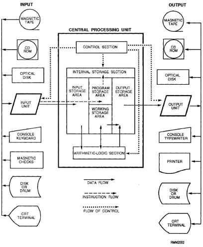
programs. Figure 1-1 shows the CPU and the types of peripheral (input and output [I/O]) devices you will find in a computer system. The devices are interconnected by electrical cables thru a bus to allow communications between them. The CPU communicates with the peripheral devices through input/output (I/O) channels.
The brain of a computer system is the central processing unit, which we refer to as the CPU. THE
CPU IS THE COMPUTER. It receives the data
transferred to it from one of the various I/O devices. It
processes the data and transfers the intermediate or final results to an I/O device for storage or distribution.
The CPU executes stored programs and does all the processing and manipulating of data. It contains the circuits that control and perform the execution of instructions using various types of memories. The I/O devices simply aid the computer by providing and receiving data and programs.
[image:14.621.113.521.193.689.2]In this section, you’ll learn about the control unit, the arithmetic-logic unit, primary storage, secondary storage, peripheral devices, I/O channels, and modems.
CONTROL UNIT
The control unit maintains order within the computer system and directs the flow of traffic (operations) and data. The flow of control is indicated by the dotted arrows on figure 1-1. The control unit selects one program statement at a time from the program storage area, interprets the statement, and sends the appropriate electronic impulses to the arithmetic-logic unit and storage section to cause them to carry out the instruction.
The control unit does n o t perform the actual processing operations on the data. Specifically, the control unit manages the operations of the CPU, be it a single-chip microprocessor or a fill-size mainframe. Like a traffic director, it decides when to start and stop (control and timing), what to do (program instructions), where to keep information (memory), and with what devices to communicate (I/O). It controls the flow of all data entering and leaving the computer. It accomplishes this by communicating or interfacing with the arithmetic-logic unit, memory, and I/O areas. It provides the computer with the ability to function under program control. Depending on the design of the computer, the CPU can also have the capability to function under manual control through man/machine interfacing.
The control unit consists of several basic logically defined areas. These logically defined areas work closely with each other. Timing in a computer regulates the flow of signals that control the operation of the computer. The instruction and control portion makes up the decision-making and memory-type functions.
Addressing is the process of locating the operand
(specific information) for a given operation. An
interrupt is a break in the normal flow of operation of a
computer (e.g., CTRL + ALT + DEL). Control
memory is a random-access memory (RAM)
consisting of addressable storage registers. Cache memory is a small, high-speed RAM buffer located
between the CPU and main memory; it can increase the speed of the PC. Read-only memory (ROM) are chips with a set of software instructions supplied by the manufacturer built into them that enables the computer to perform its I/O operations.
The control unit is also capable of shutting down the computer when the power supply detects abnormal conditions.
ARITHMETIC-LOGIC UNIT
The arithmetic-logic unit (ALU) performs all arithmetic operations (addition, subtraction, multiplication, and division) and logic operations. Logic operations test various conditions encountered during processing and allow for different actions to be taken based on the results. The data required to perform the arithmetic and logical functions are inputs from the designated CPU registers and operands.
The ALU relies on basic items to perform its operations. These include number systems, data routing circuits (adders/subtracters), timing, instructions, operands, and registers. Figure 1-2 shows a representative block diagram of an ALU of a microcomputer.
PRIMARY STORAGE (MAIN MEMORY)
The primary storage section (also called internal
storage, main storage, main memory, or just memory) serves four purposes:
. To hold data transferred from an I/O device to the
input storage area, where it remains until the
computer is ready to process it. This is indicated by the solid arrow on figure 1-1.
. To hold both the data being processed and the intermediate results of the arithmetic-logic operations. This is a working storage area within the storage section. It is sometimes referred to as a scratch pad memory.
. To hold the processing results in an output
[image:15.612.315.546.458.696.2]storage area for transfer to an I/O device.
l To hold the program statements transferred from an I/O device. This area is called the program
storage area.
Please note that the four areas (input, working, output, and program storage) are NOT fixed in size or location, but rather are determined by each individual program’s requirements.
About now, you’re probably wondering how the control unit is able to find these stored instructions and data items. To understand this, picture memory as a wall of post office boxes in a post office. Each box has a different number (address) and represents a specific storage location in memory, as shown in figure 1-3. Like the mail in a post office box, the contents of a storage location can change, but the number on the post office box or memory address does not change. In this manner, a particular program instruction or data item that is held in primary storage can be located by knowing its address. It is the responsibility of the programmer to assign descriptive names to these data items. This enables the computer program and the computer to keep track of the storage location address of each data item.
Primary storage can be classified by its physical or functional characteristics.
Memory Types by Physical Characteristics
Primary storage devices may be classified according to the type of magnetic or electronic principle they use to store data. Some of the more common types are magnetic core storage, semiconductor storage, and bubble storage.
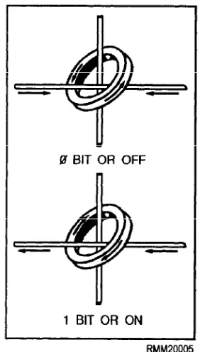
MAGNETIC CORE STORAGE.— Magnetic
[image:16.620.379.520.437.685.2]core storage, although not used as much as it used to be, provides an easy way to show the general concepts of memories, including integrated semiconductor and bubble types of memories. Magnetic core storage is made up of tiny doughnut-shaped rings made of ferrite
Figure 1-3.—Memory locations.
(iron), which are strung on a grid of very thin wires. Because computers store data in binary form (covered in chapter 3), a two-state device is needed to represent the two binary digits (bits), 0 for OFF and 1 for ON. In core storage, each ferrite ring can represent a 0 bit or a 1 bit, depending on its magnetic state. If magnetized in one direction, it represents a 1 bit, and if magnetized in the opposite direction, it represents a 0 bit. These cores are magnetized by sending an electric current through the wires on which the core is strung. It is this direction of current that determines the state of each core. Look at figure 1-4. Since the cores store data in the form of magnetic charges, core storage retains the data even when the power is off. This is called nonvolatile
storage. An example of nonvolatile storage is ROM.
However, the process of reading from core is destructive. This means the data must be electronically regenerated after being read.
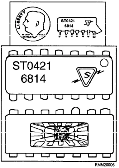
SEMICONDUCTOR STORAGE (SILICON CHIP).— Semiconductor memory has hundreds of
thousands of tiny electronic circuits etched on a silicon chip. Each electronic circuit, called a bit cell, can represent a 0 bit or a 1 bit, depending on the current flow in that bit cell. An OFF state represents a 0 bit, and an ON state represents a 1 bit. Another name you’ll hear used for semiconductor memory chips is integrated
circuits (ICs). (See figure 1-5.) Technological
developments have enabled even more circuits to be put on a single chip, resulting in large-scale integration
[image:16.620.93.280.564.686.2](LSI) and very-large-scale integration (VLSI).
Figure 1-5.—Semiconductor memory chip exposed.
Some of the advantages of semiconductor storage are fast internal processing speeds, high reliability, low power consumption, high density (many circuits), and low cost. However, a drawback to this type of storage is that it must have a constant power source. The term for this is volatile storage. An example of volatile storage is
RAM. When you turn the power to the computer off, all the stored data is lost. Also, when there is a power failure and you do not have a backup power supply, all the stored data is lost. As mentioned, this is not the case with magnetic core storage. With core storage, the data is retained even when there is a power failure or breakdown, since data is stored in cores in the form of magnetic charges, not electric current.
BUBBLE STORAGE.— Bubble memory is one of
the newer storage technologies, generally used in laptops. It consists of a very thin crystal made of semiconductor material. The molecules of the crystal act as tiny magnets. Data is stored by changing the polarity of these molecules, called magnetic domains. The magnetic domains can be switched in an opposite direction by passing a current through a control circuit imprinted on top of the crystal. Like magnetic core storage, bubble memory is nonvolatile. The data is retained even when the power is turned off or there is a power failure. Unlike magnetic storage, reading from bubble memory is nondestructive. The data does not have to be regenerated; it is still present after being read.
If we were to view these magnetic domains under a microscope, they would look like tiny bubbles; hence, the name, bubble memory. (See figure 1-6.)
Memory Types by Function
Functionally, we can classify memory by its operational features: random-access memory (RAM),
[image:17.612.130.458.442.691.2]read-only memory (ROM), programmable read-only memory (PROM), and erasable programmable read-only memory (EPROM).
RANDOM-ACCESS MEMORY (RAM).—
RAM, also called read/write memory, is like a chalkboard. You can write notes, read them, and erase them when you no longer need them. In the computer, RAM is the working memory. Data can be read (retrieved) from or written (stored) into RAM just by giving the computer the address of the RAM location where the data is stored or is to be stored. When the data is no longer needed, you can simply write over it. This allows you to use the storage again for something else. Core, semiconductor, and bubble storage have random-access memory (RAM) capabilities.
READ-ONLY MEMORY (ROM).— In most
computers, it is useful to have often used instructions, such as those used to bootstrap (initial system load) the computer or other specialized programs, permanently stored inside the computer. The memory that enables us to do this without the programs and data being lost even when the computer is powered down is read-only memory (ROM). Only the computer manufacturer can install these programs into ROM, and, once installed, they cannot be changed. Consequently, you cannot put any of your own data or programs into ROM. Many complex functions, such as routines to calculate square root, translators for high-level programming languages, and operating systems, can be stored into ROM. Because the instructions are permanently stored, they are quickly performed with accuracy. Also, your computer facility can order programs designed for its needs and have them permanently installed into ROM by the manufacturer. To describe these permanently installed programs, the term microprogram, o r
firmware, is used.
PROGRAMMABLE READ-ONLY MEMORY (PROM).— Your computer facility can also buy
programmable read-only memory (PROM) already programmed by the manufacturer or in a blank state. Using a blank PROM and a device designed to write (burn) a program into PROM, you can enter any program into the memory. However, you cannot make any changes to the program once it has been written into PROM. But, PROM does provide flexibility not available with ROM. Of course, you must be sure the program is error free before it is written into PROM.
ERASABLE PROGRAMMABLE READ-ONLY MEMORY (EPROM).— The erasable
programmable read-only memory (EPROM) was developed to overcome the drawback of PROM. Your facility can buy blank EPROMs from the manufacturer, and you can write programs developed at your command/activity using a special device. The big difference with EPROM is that you can erase it if and when the need arises. The data and programs can be retrieved many times. If you want to reprogram memory, you first erase the EPROM with a burst of ultraviolet light. This not only enables you to reprogram when requirements change, but also, you can erase and write the program again if a mistake is made while programming the EPROM. In other words, a mistake is not fatal, as it is when using PROM. You have the flexibility to change programs to include improvements or modifications in the future.
SECONDARY STORAGE
The last type of memory we briefly introduce here is called secondary storage or auxiliary storage. This is memory outside the main body of the computer where we store programs and data for future use. When the computer is ready to use these programs and data, it reads them into primary storage. Secondary (auxiliary) storage media extends the storage capabilities of the computer. We need secondary storage for two reasons. First, because the computer’s working memory (primary storage) is finite and limited in size, it cannot always hold all the data we need. Second, in secondary storage, data and programs do not disappear when power is turned off as they do when semiconductor memories are used. Secondary storage media are nonvolatile memories. This means the information is lost only if you or the users intentionally erase it. The three types of secondary storage we most commonly use are magnetic tape, magnetic disk/diskette, and magnetic drum.
PERIPHERAL DEVICES
cathode-ray tube (CRT) terminals, printers, and plotters.
Magnetic Ink Character Readers
Magnetic ink character readers read magnetically inscribed information (like on a bank check) and translate it to machine code.
Scanners
Scanners read text, drawings, and photographs and convert them into electronic representations of the images.
Bar-Code Readers
Bar-code readers scan data encoded in special bar codes using reflective light and translate them to machine code. Examples are the code on the front of this manual and the codes on supermarket and department store products.
Key-to-Online Data Entry Terminals
Using a key-to-online data entry terminal, a person enters input data into the computer directly from the point of origin. This eliminates the need for human intervention between source recording and the ultimate processing by the computer.
Magnetic Tape Units
Magnetic Disk Drive Units
Magnetic disk drive units are storage devices that read and write information on the magnetized surfaces of rotating disks. The disks are made of thin metal, coated on each side so that data can be recorded in the form of magnetized spots. As the disks spin, characters can be stored on them or retrieved from them in a random (direct) manner. This direct accessing of data has a big advantage over the sequential accessing of data. You can direct the disk drive to begin reading at any point.
Floppy Disk Drive Units
Floppy disk drive units consist of a diskette drive (the mechanism within which the diskette rotates) and a controller containing the electronic circuitry that feeds signals into and from the diskette. Diskettes are thin, flexible platters (floppy disks) coated with magnetic material so characters can be recorded on the surface in the form of magnetized spots. Just like hard disks, as the disk spins, characters can be stored on them or retrieved from them in a random (direct) manner.
Computer Consoles
Computer consoles usually include at least a display and a keyboard. They may also include a printer. The main console is located near the CPU and is used by the computer operator to control the operations of the computer system. Other consoles maybe used at the peripheral devices to specify what media to mount, what forms to use in the printer, what alignment is required, and so on. They may also be used by the peripheral equipment operator to start and stop jobs, bring up other peripheral devices, requeue jobs, and so on. Computer consoles are not normally used for keying data from source documents for production jobs.
Cathode-Ray Tube (CRT) Terminals
A cathode-ray tube (CRT) terminal looks like a television with a typewriter-like keyboard. It allows you, the operator, to enter programs and data directly to the computer. At the same time, it displays the program or data on the display screen of the CRT. It can also receive information directly from the computer and display it on the screen. You can add a printer, a modem, and adapters to the CRT terminal to provide for printed output and communications through telephone lines.
Printers
symbols, graphics, or drawings. Printers range from electric typewriters to high-speed printers. Low-speed line printers include the dot-matrix printer commonly used with personal computers. High-speed line printers are normally used with larger computers to print supply requisitions, paychecks, inventory, or financial reports at 10 lines per second and faster. Laser printers provide high quality print and print a full page at one time. They are used with all types of computers.
Plotters
Plotters are used with a computer to plot coordinate points in the form of a graph. Digital incremental plotters, in either online or offline operation with a digital computer, provide a high-speed plotting system of high versatility and reliability. For online operation, a small adapter unit converts the computer output signals to a form suitable for driving the plotter.
INPUT/OUTPUT (I/O) CHANNELS
The input/output (I/O) channels provide for communications between the CPU and all peripheral devices. This is accomplished by electrical cables that carry both data and control information to and from the computer and peripheral devices.
Signals are transmitted and received through a cable connecting the CPU and its online devices. This cable or line provides a path for the signal to travel and is called a channel. Not only signals for monitoring but also data are transmitted via channels. All channels between the CPU and the peripheral devices are designated as I/O channels. An I/O channel may be used for data input, data output, or data input and output, depending on whether the peripheral device handles input only, output only, or both input and output.
Channel Types
simplex circuits are seldom used, because a return path is generally needed to send acknowledgment, control information, or some type of error signals.
DUPLEX CHANNELS.— A duplex channel
simply means that within each cable connection, there are two paths (lines) for the transmission of data. One path is for sending, and one is for receiving, similar to your telephone. There are two types of duplex charnels, half-duplex, and fill-duplex. A half-duplex channel is capable of transmitting and receiving signals, but only in one direction at a time, similar to citizens’ band (CB) radio transmissions. Therefore, it is necessary to check that the line is clear (idle) before starting a transmission. A full-duplex channel provides for simultaneous transmission in both directions, as in the use of the telephone.
Data Transmission Methods
Data may be transmitted over a channel in one of two ways, in either serial mode or parallel mode.
SERIAL MODE.— In serial transmission,
basically only three wires are needed: one to transmit data, one to receive data, and one to ground. The data is sent or received in the form of bits, one after another in serial fashion, as shown in figure 1-7. This type of transmission is highly desirable whenever the computer system is linked to outside peripherals over a long distance, such as remote terminals.
PARALLEL MODE.— Parallel transmission is a
little more difficult to hookup than serial. It requires all the data bits in a byte to be transmitted at one time (batch mode); so you usually have nine or ten wires going between the computer and the peripheral devices. You have seven or eight lines for the data bits (figure 1-7) that make up a letter, number, or special character; one line to ground; and one or two lines called handshake lines. The handshaking signals communicate information back and forth between the peripheral device and the computer. This information lets the
I/O channels may be simplex or duplex.
S I M P L E X C H A N N E L S . — I n s i m p l e x
operations, communications are in one direction only, such as a radio. If a device such as a terminal were to be connected to such a circuit, it would only be capable of
peripheral device know when the computer is ready to accept another character and vice versa. This type of transmission is used when you want to have fast data transfer. Its drawback is that the computer cannot be too far away from the peripheral device.
MODEMS
We said that both signals and data can be transmitted and received through cables (communica-tions lines), which we refer to as I/O charnels. When we transmit data directly to the computer over long distances, it becomes necessary to add two other devices, one at each end of the communications line. These devices are called modems. The word modem is an acronym for MOdulator-DEModulator. A modem converts the digital signal produced by your terminal (or the computer) to an audio signal suitable for transmission over the communications line. The modem at the other end of the line reconverts the audio signal back to a digital signal before it is supplied to the computer (or your terminal). If this conversion were not carried out, the digital signal would degenerate and become garbled during transmission.
WORKING WITH MICROCOMPUTERS
Microcomputers are everywhere. They stand alone. They communicate with minis and mainframes. They communicate with other micros through local-area networks. This communication is accomplished by the use of software designed to make your computer system function. The operating system software enables you to install, select, and execute a variety of programs. It does this through system/job control languages and/or commands.
Microcomputer users are not often computer specialists. They are end users in the functional areas doing computer processing specific to their requirements. They need to know about the software: the operating system, the communication software, and the applications programs. They need to know about the hardware: the microcomputer, the hard disks and the floppies, the monitor, the keyboard, and the printer. You will need to help them configure (set up) the system, install the operating system and/or applications program, and troubleshoot problems.
You need to know more than just merely how to operate them if you are to become a communications
specialist. To be effective, you must keep up with the
latest changes in microcomputer technology and terminology. You must have a good working knowledge of microcomputer hardware components
(the computer, peripherals, and accessories). You should also be able to explain and demonstrate how to use the different types of systems and applications software to both computer and noncomputer personnel. Last, but not least, you should know how to use the various types of documentation supplied by the manufacturer and software vendors.
As a communications specialist, you must be able to set up, configure, upgrade, and initialize microcomputer systems. You will need to know how to install applications software so it works with the system’s unique configuration. It will be your job to help noncomputer users, end users, learn and understand everything they need to know to work in a microcomputer environment. This includes how to interconnect various peripheral devices (keyboard, monitor, printer) to the computer or system unit. It also includes how to tailor the software for the operating system and the applications software to each user’s unique hardware configuration. You need to teach them how to format and label diskettes; how to properly manage, back up, clean up, and store their files. You need to demonstrate routine operator maintenance and explain security procedures. When users are having problems with their micros, you may be called upon to troubleshoot the systems using system diagnostics to help isolate and determine whether the problem is hardware or software related. You will also be expected to make recommendations and/or arrangements to have repairs made. There will be times when you will be expected to make repairs if spare parts are available.
On microcomputers, you will need to be familiar with all types of productivity software—the program packages (or packaged software). These include word processing, spreadsheet, and database programs at a minimum. You also need to learn how to use local-area network software, communications programs, graphics programs, computer-aided design (CAD) programs, desktop publishing programs, and so on. You, as a professional data processor, may also be involved with the construction and modification of batch files. This provides a convenient way to save numerous keystrokes for the user and allow the computer to run unattended for some periods of time. All of these software functions can and have been implemented on both large and small scale computers.
are correct for a job, selecting a utility program to copy a file or create a new file by specifying the parameters, and working with an online database management system that keeps up-to-date information on inventory management or personnel.
In looking over these last few paragraphs, possibly you see yourself as a worker, a supervisor, a teacher, and a troubleshooter, and rightly so. Microcomputers make up a significant part of your profession; and because of this, you will be the person that others will come to looking for answers to their questions. The mere fact that you are a communications specialist gives the outside world, the end users, the impression you know it all; that is, all there is to know about mainframes, minis, and particularly microcomputers.
WORKING WITH HARDWARE
Microcomputers come in many shapes and sizes with a variety of capabilities. A microcomputer can be designed to operate in a stand-alone configuration or as a component, an intelligent terminal, a server for a complex local-area network (LAN) or large
distributed system. In this chapter, we will focus our
attention on desktop microcomputers that operate in a stand-alone environment. Most stand-alone, desktop microcomputer systems contain at least five hardware components. They are as follows:
. The computer or system unit, which normally houses the microcomputer (microprocessor chip[s]) along with other hardware components and secondary storage devices;
. Secondary storage devices (floppy disk drives, hard disk drives, and magnetic tape units), housed either in the system unit or separately;
. A monitor (standard output device);
. A keyboard (standard input device); and
. A printer (an additional output device—for hard copy).
THE MICROCOMPUTER
In this section, we will examine the microcomputer with its individual hardware components. We will examine it from the inside. You will see how the components work and how they interface and interconnect with one another.
There will come a time when you maybe required to replace or add a board in a computer to upgrade or expand the capabilities of the system. A few examples are as follows:
You may need to install an expanded memory board to increase the amount of RAM to accommodate larger applications.
You may have to replace the enhanced graphics adapter (EGA) board with an video graphics array (VGA) board to upgrade the graphics capabilities of your system.
You may need to install a communications board.
You may receive a new software release that requires the presence (or absence) of certain boards to function properly. You do not want to find out too late that your software is incompatible with your hardware. You might have to answer questions such as the follow-ing: Will the graphics software the user wants to order work with the graphics board currently installed in the system? Does the user’s system have sufficient room to accommodate another hard disk drive? A diagnostics routine may indicate that the disk controller board needs to be replaced, and so on, and so on. For reasons such as these, you will need to know a lot more about microc-computers (both inside and out) if you are to be effective and able to help others in your work environment.
The Computer or System Unit
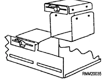
The computer or system unit is the main part or heart of the total microcomputer system. Inside this unit all data is processed, arithmetic and logic functions are performed, and control is maintained for the system. If you were to remove the outer cover from this unit (figure 1-8), you would see a power supply and as many
as two floppy disk drives and two hard disk drives or any combination thereof, depending upon the particular configuration of your system. You would also see several boards (also referred to as cards). Some boards are used to control the peripheral devices of the system, while other boards work in conjunction with the microprocessor that is located on the system or motherboard itself. These boards provide the flexibility to add a variety of capabilities to a basic system. Certain boards are required, such as the system board that contains the main microprocessor(s). Others you might add to control a light pen or mouse device, or to handle a communications interface.
Looking inside the computer system unit (figure 1-8), you will notice there are 5 available slots for board insertion. These various boards are plugged into what is called the motherboard. The motherboard is a printed circuit board that transmits the power and electronic
signals between the other boards and peripheral
devices. It is mounted to the bottom of the chassis of the computer, as shown in figure 1-9. Memory chips, on the newer micros, called single in-line memory modules (SIMMs), are located on the motherboard in a group of 4 or 8 slots. In older micros the memory chips are located on a memory expansion board. Most microcomputers also have a lithium battery installed on the motherboard. It provides power to the real-time clock when the system is turned off. The life expectancy of this battery is 3 to 5 years. Other boards you are likely to see in a typical microcomputer are the
disk controller board, SCSI adapter board, and
video display board (figure 1-9). We will take a look at
each.
SLOT A—SCSI ADAPTER BOARD.— The
small computer systems interface (SCSI) adapter board is used to control peripheral equipment, such as a CD-ROM drive.
SLOTS B, D, E, F, AND H.— Slots B, D, E, F, and
H on this particular micro are reserved for future use.
SLOT C—DISK CONTROLLER BOARD.—
Most disk controller boards are capable of supporting two internal hard disk drives, two internal floppy drives, and one external magnetic tape drive for tape backup.
SLOT G-VIDEO DISPLAY BOARD.— The
video display board includes graphics memory chips to provide the system with graphics capabilities. Most micros come from the factory set for VGA (video graphics array) settings.
By now, you should have a pretty good idea of what you can expect to see inside the system unit in the way of microcomputer boards. Before installing any internal components within the system unit, you must first carefully remove the outer cover. Be sure you are authorized to make such changes before removing the cover. However, before you go looking for a screwdriver, read the owner’s manual very carefully, paying particular attention to the section on cover removal and the steps to follow. For example, the owner’s manual might say: “Once all cabinet screws have been removed, raise the cover, keeping it as high as
possible while pulling it forward for removal.” This action ensures that none of the internal wires, cables, or connectors are accidentally pulled loose and avoids possible damage to the components already installed inside the system unit.
So that you will have a better understanding and appreciation for this microcomputer, we will take a closer look at microprocessor chips and see how they differ from one another. We will also examine what all this means to you from a communications specialist’s standpoint.
Microprocessor Chips
All microcomputer systems are driven by one or more microprocessor chips. A microprocessor chip is made up of thousands of integrated circuits that contain all of the essential elements of a central processing unit (figure 1-10). These include the control logic, instruction decoding, and arithmetic-processing circuitry.
To be useful, the microprocessor chip (which is no bigger than your fingernail) must be mounted onto what is called a carrier package (figure 1-11). This carrier package along with other chips-memory chips (RAM and ROM) and I/O integrated circuit chips—are plugged into specific socket locations on a circuit board called the system board or the motherboard (figure 1-12).
Figure 1-10.—A typical microprocessor computer chip.
Figure 1-11.—A microprocessor being mounted onto the carrier package.
Of all the boards in the microcomputer, the system board is the most important. But what are the functions of the microprocessor chip? Are all microprocessor chips designed to perform the same functions? Basically, yes; but there are some significant differences in how they perform their functions. You should be aware of these differences, especially if you will be working with several different types of micros.
A chip, is a chip, is a chip, OR IS IT? Computer chips, like everything else in data processing, have some rather unique and unusual names; names like Zilog Z-80A, Intel 80C88, MOS Technology 6502, Motorola 68000, and so on. Some chip names contain letters and numbers. Others contain only numbers. Having the right microprocessor chip in your computer
system makes all the difference in the world in terms of
internal processing speeds (33MHz, 66MHz,
120MHz, and so on), number of bits handled (8, 16, or 32 bits), memory size (640K, 4M, 16M, and up), and the applications software it will run.
E a c h m i c r o c o m p u t e r c o n t a i n s a s p e c i f i c microprocessor chip as its main processor. A microprocessor chip can typically handle 8, 16, or 32 bits of information at once. Generally speaking, the more bits a computer can manipulate at one time, the faster it can process program instructions and data, and the larger the main or primary memory it can accommodate. The type of chip in your computer or system unit also has a great effect on what you can do with your micro. For example, operating systems are written to serve a specific microprocessor chip, and applications programs that work under one operating system are not likely to work under another unless the program is modified. Many applications programs come in several versions to provide compatibility with several operating systems.
These are just a few of the reasons why we say it is very important that you read all the documentation that comes with your microcomputer. The Navy uses many different types of microcomputers and microprocessor chips. To give you an idea of the variety, table 1-1 lists some of the microprocessor chips.
Specialized Processors
Specialized processor chips have been developed to s h i f t s o m e o f t h e w o r k l o a d f r o m t h e m a i n
Table 1-1.—Microcomputer Chips and Microcomputers
microprocessor chip. For example, IBM uses an Intel 8048 chip on the keyboard to determine which keys are being depressed and also to check to see that the keyboard is communicating properly with the microprocessor. In fact, most peripheral devices have one or more specialized processors embedded in them.
Other specialized processors are the Intel 80287 and the faster 80387 math coprocessor. These are special-purpose programmable microprocessors designed to perform arithmetic calculations up to 100 times faster than the main microprocessor. A math coprocessor executes arithmetic instructions that would normally be handled by the main microprocessor’s arithmetic-logic unit (ALU) as well as those the main microprocessor cannot perform because of register constraints. The 80287 and 80387 are companion chips to the Intel family of microprocessors. Computer systems using the 80 series of chips are capable of very high-speed mathematical operations when the math coprocessor chip is plugged either into or alongside the system or motherboard. Math coprocessor chips are used in SX version computers. The SX denotes that the computer does not have a math coprocessor integrated into the cpu chip. A DX version computer has a math coprocessor integrated into the cpu chip. With the development of the Pentium chip, math coprocessor chips were no longer required to perform arithmetic calculations.
INPUT/OUTPUT DEVICES AND ACCESSORIES
To the system unit we must add input/output devices to communicate between us and the computer. These include the monitor, the keyboard, disk drives, and the printer. We will look at each of these devices in the following sections, along with some of the more common accessories found on microcomputers, such as surge protectors, parallel to serial converters and vice versa, null modems, cables, and switches used for sharing hardware.
Monitors (Display Devices)
Quite often, the term monitor is used interchangeably with such names as screen, display, display device, and cathode-ray tube (crt).
Monitors can display information in either monochrome or color, depending on their design.
Monochrome displays produce output images using a
single foreground color, such as black, and a single background color, such as white. This provides you with black text on a white background. Using a technique known as reverse video (that is, reversing the color of the pixels or dots on the screen), it is possible to have white text on a black background. Monochrome displays also come in amber (a yellowish brown) and green. Amber and green are considered more pleasing and less stressful to the eyes than black and white. Most
color displays are of the red-green-blue (RGB) type.
Depending upon the sophistication of the display device and the amount of RAM available with the microcomputer, you may be able to display from 8 to
16,000,000 colors.
Now, let’s take a closer look and discuss some of the more common features you are likely to find on moni-tors. These include brightness, contrast, and sizing. We will also discuss the various types of video display and graphics boards/cards that are used to support them.
You use the brightness control to vary the brightness of displayed data. When adjusting this control, you turn the dial until the intensity is at the brightness level desired. Use the contrast control to vary the difference between the nonintensified colors and the intensified colors.
Monitors with a sizing feature allow you to increase or decrease the physical size (the height and width) of the displayed information on your screen. Some models use control knobs. Others use two-position switches. Depending on the type monitor you have, these control knobs or switches could be located just about anywhere; on the back, on the sides, or tucked away underneath the monitor to keep them from being accidentally hit, as shown in figure 1-13.
Located on the front of most monitors, generally below the screen, you will find some type of power on/off switch. It will probably have a green light-emitting diode (LED) indicator light. When this light is lit, the monitor is on and power is supplied.
At this point, it would be helpful for you to have a basic understanding of display technology, along with the various types of display/graphics cards used to support display devices. Having a good working knowledge in this area will put you in a better position to assist the end users in answering any technical questions they may have, as well as aid you in troubleshooting and diagnostics testing.
A key characteristic of any display device is its
resolution, which determines the sharpness and clarity
of the screen image. If you look closely at your display, you’ll notice that images are formed by lighting up tiny dots on the screen. Resolution is measured by the number of these dots or pixels (short for picture elements) per square inch of screen. Whether you are working with text or graphic images, the more pixels used to form characters/images and the more pixels that can be packed per square inch of screen, the higher the resolution and the sharper the character/image. For example, a display resolution of 1280 by 1024 means that the screen consists of 1280 vertical columns by 1024 horizontal rows of dots, or if you prefer 1280 × 1024 = 1,310,720 pixels.
The distance between the dots is called dot pitch. Smaller pitch values indicate sharper images. The original IBM PC color monitor had a dot pitch of 0.43mm. The state-of-the-art displays marketed today have a dot pitch of 0.28mm or less.
Most display devices are capable of providing you with both text and graphics (pictures). Text output consists of letters, numbers, and special characters only. Text characters are created on the screen in the form of a
dot-matrix similar to a dot-matrix printing device. Nor-mally, it is the display device manufacturer who will decide on a specific matrix size—say, 7 by 12 (for a total of 84 dots or pixels) to display each character of text (see figure 1-14). The more pixels used to form charac-ters, the higher is the resolution. Most display devices use 25 rows of 80-character lines when displaying text, and there are some that will display 50 rows of 132-character lines in what is called a compressed mode.
Graphics output consists of complex picture images, which brings us to the term bit mapping. Bit mapped graphics use a technique whereby each dot or pixel on the screen can be addressed and individually controlled by the user. This allows you to create virtually any type of image on the screen. Knowing this should give you abetter understanding and appreciation of why resolution is so important, especially if you are viewing two documents on the screen at the same time, side-by-side, or working with three-dimensional graphics.
The type of monitor or display device you have on your microcomputer will often dictate what type of display/graphics board you can plug into your system unit. The key word here is compatibility. S o m e display devices can automatically switch between any standard display/color graphics card. Having such a display device or monitor allows you to upgrade the video/ graphics board in the system unit without having to upgrade the display unit. However, not all display devices are designed to accept the different types of video boards available primarily because of their resolution characteristics. It is important that you read
all the documentation that comes with your micro to
determine whether or NOT your display device will be compatible with the video/graphics board you want to install.
Figure 1-14.—The letter “L” as formed within a 7- by 12-dot matrix.
Keyboards
O f a l l t h e c o m p o n e n t s t h a t m a k e u p a microcomputer, you will become most familiar with the keyboard. It will probably be your primary means for inputting programs and data on microcomputers.
Keyboards come in many shapes and sizes, have different numbers and arrangements of keys, differ in respect to touch, and have special keys to allow you to communicate specific software commands. Most manufacturers have designed their keyboards as separate devices so you can place them wherever it is convenient. Other manufacturers have designed their keyboards into the display/monitor device or system unit.
The important things you need to know about keyboards are the types of keys and the function and placement of each. All keyboards have the alphabetic characters (upper and lower case), numbers, and some special characters. In addition, keyboards have special function keys and control keys that are defined by the operating system or the program. We will briefly describe an example keyboard and explain some of the more common keys you are likely to use.
LETTERS, NUMBERS, AND SPECIAL CHARACTER KEYS.— The arrangement of letter,
number, and special character keys may vary. The QWERTY keyboard shown in figure 1-15 has the same format as the conventional typewriter.
Figure 1-16.—Control keys.
CONTROL KEYS.— In looking at figure 1-16,
you will notice several keys are outlined in bold. These are some of the more common control keys you can expect to use when working with just about any keyboard. Beginning in the top left-hand corner, you see the ESC(ape) key, TAB key, CTRL (control) key, SHIFT key, ALT (alternate) key, and to the immediate right are the SPACE BAR and the CAPS LOCK key. On the right-hand side of the keyboard are the BACK SPACE key and the ENTER/RETURN key. Depending on what program/software you are using, the keys may be assigned different functions.
ESCape KEY The ESCAPE key usually stops
the execution of a program or functione
TAB KEY The TAB key moves the cursor to the
next tab stop position.
CTRL KEY The CONTROL key performs
special functions within the system/program. It is used in combination with other keys to increase the number of functions you can specify to a system or program. For example, on most IBM compatible systems, when used with the ALT and DEL keys, it reboots the operating system.
SHIFT KEY The SHIFT key works in
conjunction with other keys. When you hold down the shift key (or depress the CAPS LOCK key) and press a letter key, the letter will be displayed and stored in UPPER CASE. When you hold down the shift key with the number keys on the row above the alphabetic keys, the special characters shown on the top of each key will be displayed and stored. The CAPS LOCK key on this particular keyboard contains a light within the key itself. When it is lit, you know the caps lock feature is on.
ALT KEY The ALTERNATE key also works in
conjunction with other keys to increase the number of functions you can communicate to the system/program.
SPACE BAR Press the SPACE BAR whenever
you want to enter a blank character, a space.
BACK SPACE KEY Pressing the BACK
SPACE key moves the cursor one position to the left, erasing the character that was previously entered.
ENTER/RETURN KEY By pressing the
ENTER/RETURN key, you tell the computer (microprocessor) you have entered data or instructions and are ready for processing. Depressing this key also returns the cursor to the beginning of the next line.
SPECIAL FUNCTION KEYS.— If you look at
figure 1-17, you will notice once again several keys outlined in bold. These are special function keys you can expect to use. Located on the far left side of the keyboard, you see 12 special function keys labeled F1 through F12. On some keyboards you will find these function keys have been placed across the top of the keyboard, above the letters and numbers. The number of these function keys may also vary. To the right of the keyboard is another group of special function keys.
These include a 10 key (0-9) numeric keypad and the cursor control keys. Also, beginning on the top row at the right, you see the NUM(eric) LOCK key, SCROLL LOCK key, PAUSE key, and the PRT SC (print screen) key. Located on the bottom right-hand side of the keyboard are the INS(ert) and DEL(ete) keys. The purpose/function of each of these keys is as follows:
FUNCTION KEYS F1-F12 These
special-purpose keys are used to communicate special functions to the operating system, such as MS-DOS, or to applications software. The meaning of each is defined by the particular software. This simplifies tasks that might otherwise require several keystrokes. These keys can also be used with other keys to increase the number of functions you can specify to a program.
NUMERIC KEYPAD KEYS To activate the
numeric keypad, press the NUM LOCK key. The NUM LOCK key may contain an indicator light within the key to indicate when it is ON. Use the numeric keypad just like a calculator keypad to enter numbers you will be using in mathematical functions.
CURSOR CONTROL KEYS The CURSOR
CONTROL keys are most important. They allow you to move the cursor from one place to another on the display screen. Remember, the cursor is the indicator, the spot of light on the screen, which lets the user know where the next entry will be made. On the keyboard shown in figure 1-17, the cursor control keys are located in two locations, both on the numeric keypad and as a separate keypad. When the NUM LOCK key is
OFF, you can use the arrows on keys 2,4,6, and
8 to control cursor movement one line up or down, or one position to the left or right, as shown by the direction of the arrow. The remaining cursor control keys on keys 1, 3, 7, and 9 are used to move the cursor to other parts of the screen or document/data (for example, the end of a line [END key] or the top of the next page [PgDn key]). Some software packages use the cursor control keys in combination with each other or with other keys to increase the number of ways and the speed with which you can move the cursor. Read the software documentation; the faster and more efficiently you are able to move the cursor through a document or database, the faster and more efficiently you will get the job done. Some keyboards have separate arrow keys
for cursor control. This is particularly helpful when you are doing a lot of data entry of numbers.
SCROLL LOCK KEY Applications software
uses the SCROLL LOCK mode of the key to control screen scrolling.
PAUSE KEY The PAUSE key is used to
interrupt program execution.
PRT SCreen KEY The PRT SCREEN key is
activated by depressing it in conjunction with the SHIFT key depressed. This sends whatever is displayed on the monitor’s screen to the printer.
INSert and DELete KEYS These keys allow
you to insert or delete a character at the position of the cursor when neither the SHIFT nor the NUM LOCK keys are depressed.
It is important to remember that any key or combination of keys can be assigned special meaning by a program. Therefore, the keys may have different meanings and functions, depending on the program you are using. Once again, we remind you, read all the documentation that comes with each program and with the computer system.
Disks and Disk Drives
Magnetic disks, regardless of their type or size, are, without a doubt, the most important secondary storage medium used with microcomputers. Disks provide fast retrieval of information. The disk’s physical characteristics, flat and round, allow the disk drive
direct access to data. Put simply, the processing unit
goes directly to a designated disk drive, seeks out the specific location on the disk where the data is stored, and immediately retrieves it. The disk drive does NOT have to read through a series of records before reaching the one desired, as is the case with magnetic tape units. The two forms of magnetic disk typically used with microcomputers are the floppy disk (diskette) and the
hard disk. Let’s look at the sizes and construction of
each and at the disk drive devices that read from and write to them.
DISKETTES AND THEIR DRIVES.— A
diskette is also referred to as a floppy disk, or just plain floppy, because it is a round, flexible platter.
Physical Characteristics.— The platter is
(3.50) inches (see figure 1-18). The platter is made of a tough plastic that is coated with a magnetic oxide material, allowing it to be magnetized. The inside of the plastic jacket is lined with a soft wiping material that continuously cleans the floppy disk as it spins within the jacket. Look at figure 1-19; you will notice a hole in the middle of the diskette. It is referred to as the center
hub. The hub makes it possible for the floppy disk
drive’s spindle to rotate the diskette inside the jacket. The recording window allows the read-write head mechanism of the floppy disk drive to come into contact with the diskette so it can read from or write data onto the diskette’s surface. Located just to the right of the center hub is what we refer to as an index hole. This index hole (and corresponding hole [or holes] in the diskette), marks the first sector or starting point on the diskette. The sectors on a diskette are controlled by timing. On a soft-sectored diskette, the timing is controlled by the software; therefore, only one timing hole is needed on the diskette. On a hard-sectored diskette, the timing is controlled by the hardware, and the diskette has several timing holes.
Types of Floppies/Diskettes.— The diskettes you
will be using must be compatible with the floppy disk drives on your microcomputer system. Diskettes can be
soft-sectored or hard- sectored. Depending upon the
disk drive’s characteristics, the disk drive can record data on one side of the diskette or both and can record data in one of several bit densities, depending upon how the diskette is formatted.
When you are working with a soft-sectored diskette, you must use your microcomputer and a utility routine or program (in this case, a formatter program) to sector or format each diskette for you. On most microcomputer systems, using the F O R M A T command will automatically sector the diskette for you.
If you are working with hard-sectored diskettes, then you need not format them. They have already been presectored by the manufacturer for your specific
Figure 1-18.—Floppy disks/diskettes used on microcomputers.
Figure 1-19.—A typical 5.25-inch diskette.
microcomputer system. Floppy disk drives that use
hard-sectored diskettes read and write data faster. However, the diskettes are more expensive and can only be presectored (reformatted) for a specific system, such as an IBM compatible or a Macintosh.
Most diskettes sold today are soil-sectored because the wide range of microcomputers and their operating systems vary considerably in respect to sectoring re-quirements. For now, the important thing to remember about sectoring is the fact that no matter what type of diskette you are working with (soft- or hard- sectored), it must be formatted before it is usable for storing data.
Storage Capacity.— Although diskettes are
relatively small in size, they can store a respectable amount of data. Some diskettes are single-sided,
single-density, whereas others are double-sided, single-density; double-sided, double-density; or double-sided, quad-density.
To review, multiply bytes (5 12) times sectors (15) times tracks (80) times sides (2). This gives the total capacity of the diskette, 1.2M bytes.
Write Protect Feature.— Like all other media,
floppy disks/diskettes must also have a way of being protected from a user accidentally writing on them. This is accomplished with a write-protect notch (or cut-out) located in the upper right-hand corner of the plastic jacket (see figure 1-19). Whether or not the write-protect notch is covered to protect the data on the diskette depends solely on the disk drive manufacturer. For example, on most systems using 5 1/4-inch diameter diskettes, covering the write-protect notch makes it impossible to write on the disk’s surface. However, the opposite is true on systems using 3 1/2-inch diameter diskettes. Uncovering the write-protect notch makes writing impossible. In short, find out which is which on your particular system before you accidentally wipe out an entire diskette’s data.
Floppy Disk Drives.— Floppy disk drives are
manufactured to read and write data in one of several bit densities for both single- and double-sided diskettes. A single-sided disk drive can only read a single-sided diskette. However, a double-sided disk drive, like the one shown in figure 1-20, can read both a single-sided and a double-sided diskette.
H A R D D I S K S A N D H A R D D I S K DRIVES.— Although most microcomputer systems
you will be working on use some type of floppy disk drive, you should also be aware that all micros also contain a small sealed unit called a Winchester disk or
hard disk drive. Unless the disk drive is an external
[image:32.614.98.278.540.676.2]type unit, you might never know it was there. Floppy disk drives are easy to spot; all you have to look for is the drive’s door, that open slot where you insert the diskette. Hard disk drives, on the other hand, are normally sealed
Figure 1-20.—A floppy disk drive being removed from system unit.
Figure 1-21.—Internal hard disk drive mounted on disk drive chassis.
units that can be tucked away just about anywhere. Generally, you will find them inside the system unit (figure 1-21) in the space occupied by one of the floppy drives.
Hard disk drives provide you with many timesaving features not available nor possible with the floppy disk drives. These include increased access speeds, greater storage capacity (up to 8 gigabytes [GB] of storage), and overall convenience. Working with hard disk is much easier because you can quickly end one program and start another, all through the operating system.
Hard disk units consist of rigid metal platters that are tiered or stacked. In most cases, the disks themselves are not removable, and for this reason can be hermetically sealed in the storage unit along with the access mechanism that contains the read/write heads. Because this type of disk drive is completely sealed and free from air contamination, the read-write heads can be positioned to within 20 millionths of an inch from the surface of the disk. This also allows the disk to be rotated at a high rate of speed-typically, 3600 revolutions per minute. Hard disks also comes in two sizes (diameters): 5.25 inches, and 3.50 inches, with 3.50 being the most popular. Their storage capacities range from 500 megabytes to 8 gigabytes, with the majority in the 1.2- to 2-gigabyte range.
Figure 1-22.—External hard disk drive with removable disk cartridge.
Printers
Most printers you are likely to use while working on microcomputers are the low-speed varieties. They are able to print text at rates of 200 to 800 characters per second and usually output this information one character-at-a-time. After close examination, you will find that basically the only major difference between printers designed for micros and those used on larger mainframes is their size, and the speed at which they print. Other than that, they are very much alike in terms of setup, operation, and operational features.
Micro printers, like mainframe printers, are either impact or nonimpact. At least six printing technologies are used to produce hundreds of microcomputer printer models. These technologies include dot-matrix (which forms characters using a series of dots), xerographic, electrostatic, ink jet, and laser.
DOT-MATRIX PRINTER.— The dot-matrix
printer uses a print head made up of pins. It creates the characters by using these pins to generate characters a dot-at-a-time. Dot-matrix printers have speeds that range fro