J
I
SERIES
400
PRODUCT
DESCR I PT I ON
MANUAL
#
852-03
SERIAL, POLLING,
BUFFERED, MESSAGE ORIENTED
DATA-SCREENTM Terminals
Model 420: 1000 Character Display, 50 Characters/line x 20 lines
Model 425: 1920 Character Display, 80 Characters/line x 24 lines
Model 426: 960 Character Display, 40 Characters/line x 24 lines
OLDEST INDEPENDENT COMMERCIAL CRT TERMINAL MANUFACTURER
20 APRIL 1978 $5.00
ACTION-SECTION
SECTION II
SECTION III
SECTION IV
SECTION V
SECTION VI
SECTION VII
TABLE OF CONTENTS
INTRODUCTION
System Compatibility Model Description Options & Accessories
INSTALLATION
Unpacking
Equipment Placement PCB Option Settings Power On/Adjustments
OPERATING INSTRUCTIONS
Keyboard Familiarization Encoding Keys & Functions
Graphic Keys Control Keys Cursor Control Keys Text Editing Keys Blank Function Keys Message Transmission Keys I ndicators and Switches Comp
Computer Command Functions Communications
Communication Line Control Options
Blink Commands
Format Protect Commands Lock Commands
Mode Commands Read Commands
Cursor Address Commands DATA.PANEL8 0isplay Commands Bell Command
Keyboard and Communications Code Summary
THEORY OF OPERATION
I ntroducti on Model 420 Model 425 Model 426
Parallel I/O Adaptor
Message Oriented Serial Interface
OPTIONS
PCB Option Settings DATA·PANEL Display Print Adaptor
SPECI FICATIONS
General
Outline Drawings Spare Parts
TROUBLE SHOOTING GUIDE
WARRANTY
DATA-SCREENe, DATA·PANEL8, ARE INFORMATION DISPLAY AND CONTROL
PRODUCTS MANUFACTURED BY TEC, INCORPORATED
FIGURE 1 2 3 4 5 6 7 8 9 10 11 12 13 14 15 16 17 18 19 20 21 22 23 24 25 26 27 28 29 30 31 32 33 34 35 36 37 38 39 40 41
iLLUSTRATIONS
TITLE PAGE
DESK TOP MODEL WITH MONITOR 2
RACK MOUNT WITH MONITOR 5
RACK MOUNT WITHOUT MON ITOR 7
SYSTEM DIAGRAM, MODELS 420, 425, 426 9
BACKPANEL CONNECTIONS 10
KEYBOARD, MODELS 420, 425, 426 12
CURSOR CONTROLS & EDIT KEYS 14
BLANK FUNCTION KEYS 18
MESSAGE TRANSMISSION KEYS 19
KEYBOARD INDICATORS & SWITCHES 20
INTERFACE DATA BIT SEQUENCE 22
KEYBOARD CODE CHART 28
COMMUNICATIONS CODE CHART 29
FUNCTIONAL DIAGRAM - TIMING GENERATOR PCB 59
FUNCTIONAL DIAGRAM - LINE MEMORY AND CHARACTER GENERATOR PCB 60
FUNCTIONAL DIAGRAM - PAGE MEMORY PCB 61
FUNCTIONAL DIAGRAM - CONTROL PCB 62
FUNCTIONAL DIAGRAM - COUNTER PCB 63
OUTPUT ACKNOWLEDGE SEQUENCES 67
KEYBOARD STROBE SEQUENCES 68
INPUT ACKNOWLEDGE SEQUENCES 69
PARALLEL I/O ADAPTOR INTERFACE SIGNALS 70
FUNCTIONAL DIAGRAM - PARALLEL I/O ADAPTOR PCB 71
EXTERNAL INTERFACE CONNECTIONS 76
SWITCH OPTIONS ON MODEL 425 TIMING GENERATOR PCB 78
SWITCH OPTIONS ON MODEL 420 TIMING GENERATOR PCB 79
SWITCH OPTIONS ON MODEL 425 LINE MEMORY AND CHARACTER GENERATOR PCB 80
SWITCH OPTIONS ON MODELS 420 & 426 LINE MEMORY & CHARACTER GENERATOR 81 PCB
JUMPER WIRE CONNECTIONS ON MODELS 420, 425, 426 CONTROL PCB 82
SWITCH OPTIONS ON MODELS 420, 425, 426 PARALLEL I/O PCB 83
SWITCH & JUMPER OPTIONS ON MODELS 420, 425, 426 ME:SSAGE ORIENTED 84 SERIAL INTERFACE (DSA INFC) PCB
DATA·PANEl DISPLAY CONNECTIONS 85
DATA·PANEl DISPLAY ASSEMBLY 85
DATA·PANEl DISPLAY CODES 85
DATA·PANEl DISPLAY ORDERING INFORMATION 86
FUNCTIONAL DIAGRAM - PRINT ADAPTOR PCB 88
JUMPER WIRE OPTIONS ON MODELS 420, 425, 426 PRINT ADAPTOR PCB 89
PRINT ADAPTOR INTERFACE SIGNALS 91
PRINT ADAPTOR TO PRINTER CONNECTIONS 92
KEYBOARD DIMENSIONS 96
SECTION I
Ir~TRODUCTION
TEC, Incorporated has been a leader in the display and communications field for over a decade, DATA-SCREEN Terminals have been operating throughout the United States, Canada, Europe and the Far East for several years. During this time TEC has inten-sively studied and evaluated numerous user applications and incorporated many impor-tant features in the Series 400.
Series 400 D isp lays are a fou rth generatio n fam i I y of CRT displays m a nufactu red by TEC. The technology and history accrued on the earlier models plus latest state-of-the-art developments, proved reliability, and handsome styling make the Series 400 one of the finest displays available today.
Series 400 DATA-SCREEN Terminals are self-contained, desk-top or rack mount-ed units designmount-ed to operate with a processor in interactive time-sharing applications.
This manual is designed to acquaint operators, programmers and engineers with the features of Models 420,425, & 426 DATA-SCREEN Terminals.
SYSTEM COMPATIBILITY
Series 400 D ATA-:-SC R E EN Term inals provide a versatile, econom ical operator-oriented input/output station, The operator may interact with the processor or remove the Terminal from computer control to co,!!pose or edit a message for subsequent transmission. Sixty-four ASCII graphic characters and four special symbols may be displayed using a 5 x 7 dot matrix.
MODEL DESCRIPTION
Three models are available and may be ordered with or without monitor or key-board and with or without enclosure. See Figures 1 through 3.
The three models differ in character display capacity:
Model 420 1000 character display, 50 characters/line x 20 lines. Model 425 1920 character display, 80 characters/line x 24 lines. Model 426 960 character display, 40 characters/line x 24 lines.
See Figures 40-42 for actual size photographs of these screen capacities.
OPTIONS & ACCESSORIES
All models have the following basic options: Display or blank Carriage Return symbol Display or blank Cursor
Enable or disable Automatic Line Feed Enable or disable Automatic Roll-Up
Enable or disable End of Line/Page Bell signal Enable or disable Operator Lock Over-ride EaT, Message or Poll transmit modes. Set: Parity, Stop bits, Baud rate
Displays white on black or black on white.
A II models h ave the capab ility of add i ng on th e follow ing accessories:
Printer Adaptor (20 ma current drive or TTL direct drive)
Slave Monitors (one or more can be connected in series from the BNC, VIDEO OUT, connector on the back panel). No adjustments are required in the Terminal.
All models with integral monitor may include optional fixed message indicators (DATA·PANEL Display).
SECTION II
INSTALLATION
The Series 400 Terminal has been carefully packed to insure its arrival in operating condition; however, damage may have occured during shipment or handling, therefore the following procedures should be used to establish the mechanical condition of the unit and prepare it for operation.
UNPACKING
.Inspect the shipping carton for external damage, note any damage on the Bill of Lading prior to opening the carton.
·-As the equipment is unpacked, check for signs of damage or missing parts (refer to Spare Parts List for parts identification). Note, any damage or missing parts on the B ill of Lad ing for possible claim s.
·Check inside the unit for foreign materials, loose nuts screws, bent pins, shorted or broken connectors, broken wires, etc ..
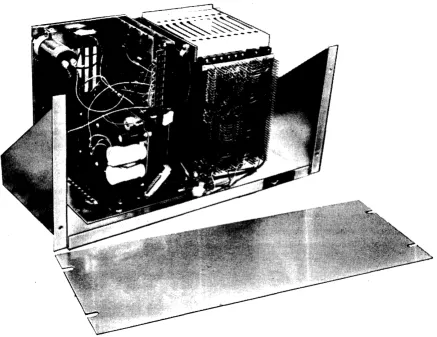
To remove the top enclosure on desk top model with monitor, undo the three, 14 turn fasteners on the back panel, pull back the two slide latches (at the bottom rear corners) and push forward and upward (enclosure rotates from the bottom front).
To remove the top enclosure on desk top model without monitor, undo the % turn fasteners on each end and lift straight up.
EQUIPMENT PLACEMENT
DATA-SCREEN Terminals are available in four configurations:
a. Desk top; with logic, power supplies and TV monitor. See Figures 1 and 41.
b. Desk top; without TV monitor but with logic and power supplies. For use with remote TV monitors. See Figures 2 and 41.
c. Rack mount (for standard 19-inch rack) with 12 %" high front panel. Consists of TV monitor, logic and power supplies. See Figures 2 and 42.
d. Rack mount (for standard 19-inch rack) with 10 %" high front panel. Accomodates logic and power supplies only. Designed for use with remote monitors. See Figures 3 and 42.
DESK MOUNTING
Two desk-mount Series 400 Terminals are self-contained and include an attractive enclosure and non-scuffing rubber feet for protection of desk and table tops. Connectors are provided for power (2-wire plus ground), detachable keyboard, video output for remote TV monitor and communication line (telephone-mod~m
or direct connection to computer). Clearance is required for convection cooling of electronics.
RACK MOUNTING
Two rack mounting options are available for mounting DATA-SCREEN Termin~ls
FIGURE 3. RACK MOUNT MODEL WITHOUT MONITOR
[image:10.613.92.529.147.484.2]PCB OPTION SETTINGS See Section V
o
ptiona I featu res that are en abled by sw itches or ju m per w ires are preset at the factory. To insure that these features meet your requirements, remove printed circuit boards LM & CB (position 2), CONTROL (position 4), PARA I/O (position 6) and DSA INTFC (position 8) from the card cage. Refer to F igu res 27 th ru 31 for sw itch and jum per w ire locations. Set sw itches Cln~install jumpers accordingly.
40/50 CHARACTER LINE SWITCH MUST BE SET TO 40 CHARACTER LINE FOR MODEL 426 AND 50 CHARACTER LINE FOR MODEL 420. ALTERNATE SETTING WILL SHIFT CHARACTER SCANNING AND DISPLAY "GARBAGE",
Replace the four PCB's and check the remaining PCB's for card guide allgnm~nt
and socket engagement.
IPOWER ON/ADJUSTMENT (Refer to FIGURE 5)
Before applying power to the Term inal:
• Turn the POWER switch on the backpanel to OFF.
• Plug the keyboard cable into K B-J3 on the backpanel.
• Attach the power cord to the POWER CONNECTOR on the back panel and to a standard 115V AC, 60Hz 3-hole grounded outlet, (or to ~49VAC::
if so ordered).
CUTTING THE SAFETY GROUND PIN ON THE POWER CORD FOR USE WITH A 2 HOLE SOCKET WI LL PRESENT A SHOCK HAZARD. USE A 3 PRONG ADAPTER WITH SAFETY GROUND PROPERLY CONNECTED.
Turn the POWER switch to ON. When power is applied to the unit. th~ POW~R
cpn-"T1 G) C :0 m
.J::-en
-<
en
-i ms:
o
»
G) :0»
s:
Is:
o
o
m ren
.J::-~ o .J::-~ U1 .J::-~ 0') BASIC 400 SERIES DATA - SCREEN DISPLAY LOGICDATA·PANEL
I
OPTION1 L
L __
KEYBOARD
SERIAL I/O ADAPTOR
1 • •
-J3 · ·
-MULTI-DISPLAY SYSTEM (FULL DUPLEX ONLY)
MODEM OR
PROCESSOR
-,
_ _ _
..,~Terminal
1 ...J~
__
~1L 1-~---'*
~\~~=2=======:_-J'*
L
PRINT ADAPTOR OPTION- I
J4 MODEM, PROCESSOR, MU L TIPLEXOROR COMPUTER
NEXT 400 SERIES DATA-SCREEN TERMINAL
r--_ _
...,,~lT.'min.,
2 . . . . 1r _
J1Terminal 63r-\J2
--\1
L_-= ___ - - -
-.J
DESK TOP MODEL
With Monitor
RACK
MOUNT
MODELS
,With & Without Monitors
I/O
J1D
~~D
0
O
KBJ3 PTR
J4
~~D
0
J2D
o
KBJ3 PTR
J4
VIDEO OUT
o
ON POWER OFFm
2A OFUSE
~~~OOPOWER
CONNECTORVIDEO
OUT
o
ON POWER OFFm
2AOFUSE
120V
Gl
POWER 60Hz~CONNECTOR
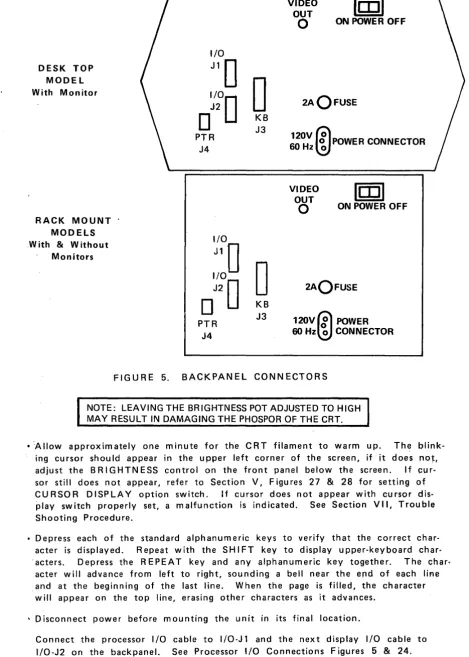
FIGURE 5. BACKPANEL CONNECTORS
NOTE: LEAVING THE BRIGHTNESS POT ADJUSTED TO HIGH MAY RESULT IN DAMAGING THE PHOSPOR OF THE CRT.
• '-Allow approximately one minute for the CRT filament to warm up. Th~ blink-ing cursor should appear in the upper left corner of the screen, if it does not, adjust the B RIG H T NESS contro I on the front panel below the screen. I f ~u r-sor still does not appear, refer to Section V, Figures 27 & 28 for setting of CURSOR DISPLAY option switch. If cursor does not appear with cursor
dis-play switch properly set, a malfunction is indicated. See Section VII, Trouble Shooting Procedure.
• Depress each of the standard alphanumeric keys to verify that the correct char-acter is d isp layed. Repeat with the S HI FT key to display upper-key board char· 'acters. Depress the REPEAT key and any alphanumeric key together. The char,
acter will advance from left to right, sounding a bell near the end of each line and at the beginning of the last line. When the page is filled, the character will appear on the top line, erasing other characters as it advances.
• Disconnect power before mounting the unit in its final location.
[image:13.615.76.546.32.689.2]SECTION III
OPERATING INSTRUCTIONS
The bench check out procedures will have prepared the DATA-SCREEN Terminal for on-I in e operatio n however, th e 0 pe rator shou Id fa mil iarize him self with the key board
keys and their functions, especially those used for control, editing and message com-position.
KEYBOARD FAMILIARIZATION (Referto FIGURE 6)
The Series 400 keyboards are easy to operate because a standard keyboard arrange-ment is used. To practice, turn on power (POWER switch on backpanel). Allow approximately one minute for the CRT to warm up. Depress the LOCAL switch on the keyboard (LOCAL indicator will light) to "Iock out" the processor and prevent term inal/processor interaction,
IF THE KEYBOARD APPEARS TO BE INOPERATIVE (WAIT INDICATOR ON) TOGGLE THE POWER SWITCH TO OFF-ON. THIS WILL RELEASE THE KEYBOARD FROM PROCESSOR CONTROL.
Program note
Any of the functions described for the keyboard except LOCAL, REMOTE & REPEAT can be implemented by the processor by outputting the proper codes. See Figures
12 & 13. Those functions controlled exclusively by the processor are described u nd er Co m pu ter Com m and F u nc-tions beginning on page 22.
ENCODING KEYS AND FUNCTIONS
There are 65 encoding keys and two encoding switches on the keyboard used for the Series 400 terminals. They generate 84 ASCII codes, (referred to in hexadecimal notation in this manual, See Figures 12 & 13) that are trans~
."
G)
c
::c
m0')
A m
-<
to0
»
N
::c
0
s::
0 0 m
r
en
~
N
0
~
N U1
~
N
0')
POWER
0 0
WAITLOCAL
0
OSEG MODE
RE-MOTE LOCAL
CURRENT KEYBOARD EKA-8001
PRINT X-MIT
STX
BACK
::::::::::::~:::::::::::::J SPACE RPT
CS. CM.
I.C
+
I.l."
-+ HOME
,
....
D.C
•
D.l. EEOL EEOP"
HOME CS. CM."'
....
-+
I.C D.C•
I.l. D.LGRAPHIC KEYS
Sixty-four graphic characters including space are displayable from a pos-sible 95 ASCII characters. The 64 characters are contained in the center four columns of USAS X3.4-1967, USASCII and are generated by the shaded keys shown in FIGURE 6. The SHIFT key has the standard function of selecting upper keyboard characters. It has no effect on single character keys.
CONTROL KEYS
,
Several control functions are generated by keys on the main keyboard. They are CR, REPEAT & TAB.
C R (Carriage R etu rn) KEY - When the C R key is depressed, ASC II code
0
D is generated, The CR symbol (~) will be displayed at the cu rsor position unless it is disabled. Th e cu rsor will move to the beginning of the next line unless the Auto-Line Feed option is disabled, causing the cursor to move to the beginning of the same line.REPEAT KEY - This key is used in conjunction with another char-acter or control function key to repeat the charchar-acter or control function at a 15 Hz rate for as long as both keys are depressed.
TAB (Field Tab) KEY - When the TAB key is depressed, ASCII code 09 is generated. The cursor moves to the position immed-iately following the next tab stop. If no tab stops are present, the cu rsor moves to the Hom e position (top left corner of the screen) .
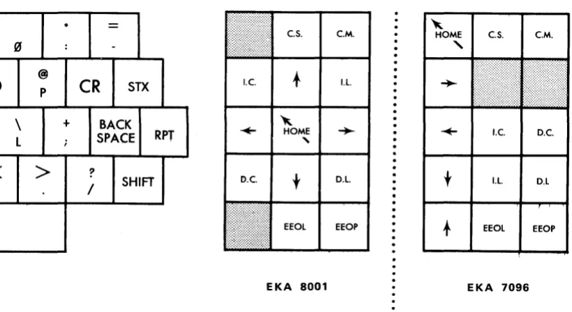
CURSOR CONTROL KEYS
cs. CM. cs. CM.
I.C D.C
LL. D.L
EEOL EEOP EEOL EEOP
EKA 8001 E KA 7096
FIGURE 7. CURSOR CONTROLS AND EDIT KEYS
The five shaded keys shown in FIG U R E 7 are located to the ri{Jht of the main keyboard. They are used to manually position the our-sor on the screen. The arrows on the keys indicate the direction of the movement when the key is depressed. Use of the REPEAT key with a cursor control key will speed positioning of the cursor.
HOME ( " ) KEY - Moves the cursor from any position on the screen to the top line, first column.
DOWN (
t )
KEY - Moves the cursor down one line, in the same column. When on the bottom line, cursor moves to the same col-umn on the top line. Auto-Roll-Up is by passed.LEFT (~) KEY - Moves the cursor left one position. When in the first column, cursor moves to the last column of the line above. When in the Home position, cursor moves to last column of bottom line.
BACKSPACE KEY - Identical to LEFT (~) KEY
RIGHT (-+-) KEY - Moves the cursor right one position. When in the last column, cursor moves to first column of line below. When in the last column of the bottom line, cursor moves to Home posi-tion.
TEXT EDITING KEYS
The eight unshaded keys shown in FIGURE 7 are located to the right of the main keyboard. They are used to simplify text editing and cor-rections. Characters or lines of characters can be inserted and any or all characters deleted. The terminal also has the capability of assisting the operator to edit or compose messages by blinking characters and preventing the alteration (form at protect) or characters. See Com puter Command Functions.
To prevent an edit function from being accidentally enabled, the editing keys must be depressed in conjunction with a SHIFT key.
CM (Clear Memory) KEY - When the CM & SHIFT keys are de-pressed, spaces (ASCII 20) appear in all positions including pro-tected positions. The screen is com pletely blank except for the cursor which moves to the Home position.
IC (Insert Character) KEY - When the IC & SH 1FT keys are de-pressed, the character over the cursor and all characters to its right in that line are moved to the right one position. The char-acter in the last colum n of the line is lost. A space appears at the cursor position allowing a character to be inserted. The IC function is disabled if any position on the screen is protected (See Com puter Com m and Functions - Form at Protect).
IL (Insert Line) KEY - When the IL & SHIFT keys are depressed, the line containing the cursor and all lines below it are moved down one line, losing all characters in the bottom line. The cursor moves to the first column of the same line and the line is filled with spaces allowing a new line of characters to be inserted. The cursor can be in any position in the line to perform this function, how-ever the function is disabled if any position on the screen is pro-tected (See Com puter Com m and Functions - Form at Protect).
D L (Delete Line) KEY - When the D L & SH I FT keys are depressed, the line containing the cursor is replaced by the line below and all lines following it are moved up one line. Spaces are inserted in the bottom line and the cursor moves to the first colum n of the de-leted line. The cursor can be in any position in the line to per-form th is fu nctio n, however the fu nction is d isab led if any posi-tion on the screen is protected (See Computer Command Func-tions - Form at Protect).
EEOL (Erase to End of Line) KEY - When the EEOL & SH 1FT keys are depressed, the character in the cursor position and all characters to its right in the line are replaced by spaces, except for those characters that are protected (See Computer Command
Functions - Format Protect). The cursor does not move.
EEOP (Erase to End of Page) KEY - When th'e EEOP & SHIFT keys are depressed, the character in the cursor position and all characters to its right and in the lines below are replaced by spaces, except those characters that are protected (See Computer Command Functions - Format Protect). The cursor does not move.
BLANK FUNCTION KEYS
0
)
\
L
/
"
•
=
~e.s. C.M. HOME e.S. e.M.
:
-"
@
P
CR
STXI.e.
t
I.l...
+
BACK; SPACE RPT
~
-+- HOME
,
..
I.e. D.C.>
?SHIFT
/
I!>.e.
t
D.L.t
I.l. D.LEEOL EEOP EEOL EEOP
EKA 8001 EKA 7096
FIG U R E 8. B LAN K FUN C T ION KEY S
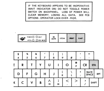
MESSAGE TRANSMISSION KEYS
Th e th ree shaded keys show n in FIG U R E 9 are used tQ notify th e prq-cessor or printer that a message is ready for transm ission and to define the limits of that message.
[image:21.613.143.553.189.413.2]E
X-M IT (Transm it) KEY - When the X-M IT key is depressed an ETX (End of Text) ASCII code 03 is generated and the symbol (.J)
appears in the cursor position to define the ending of the message to be transmitted. The cursor moves backwards until an STX posi-tion is found (SEGMENTED MODE) or to the Home posiposi-tion (PAGE MODE). See Computer Command Functions - SEG/PAGE MODE. The message is transm itted to the processor via one of three modes;
EOT, Message or Poll. See OPTIONS - PCB OPTIONS. The
key-board is disabled until it is released by the processor.
IF THE KEYBOARD APPEARS TO BE INOPERATIVE (WAIT INDICATOR ON) DO NOT TOGGLE POWER
SWITCH ON BACKPANEL. LOSS OF POWER WILL
CLEAR MEMORY, LOSING ALL DATA, SEE PCB
OPTIONS - OPERATOR LOCK OVER -
RipE.
~ ~~t! POWE;R
0 0
WAITRE-MOTE LOCAL
$
.4D
. . . LOCAl,
0 0
S~G MODE%
5
R
T
F
c
v
& 6
G
y
B
7H
u
A
N8 9
J
K
M
o
<
\
l @P
>
+
=
CR
?/
BACKSPACE RPT
SHIFT
[image:22.612.120.524.320.673.2]PRINT KEY (See Options - Printer Adapter) - When the Print Key is operated, code
6a
is generated. If the Printer is not ready or doesn't ex ist th is code is ig nored. I f the Printer is Ready, the cursor is moved to the first previous STX if the terminal is inSEGMENTED MODE or to Home if in PAGE MODE. Data is
then transmitted to the printer excluding only characters to the right of a Carriage Return on a line. Printing will end at ETX in SEGMENTED MODE or the end of the page in PAGE MODE. The keyboard and processor are both locked out during a Print operation. See 0 ptions - Printer Adaptor.
INDICATORS & SWITCHES
~f'l:'t~ POWER€)
0
WAIT ... LOCAL Q () SEG MODEPRINT X-MIT
\.
...
_----V
_ _ _ _ _ ...,,1
INDICATORS SWITCHES
#
$
% &,
(
) *=
3 4- 5 6 7 8 9 (if :
-V
E
R
T
y
U
I
0
@ pCR
Sl~ __ L
-FIGURE 10 KEYBOARD INDICATORS & SWITCHES
The shaded indicators and switches shown in FIGURE 10 are used to control and report the communications mode between the terminal and the processor.
POWER INDICATOR - When lit, indicates power is applied to the term inal and keyboard.
SEG MODE INDICATOR - When lit, indicates that the processor has placed the terminal in SEGMENTED MODE, therefore only those characters between the STX
L1..
symbol) and ETX (..J
sym bol) w ill be transm itted. W hen the ind icator is not I it, the, terminal is in the PAGE MODE and all unprotected characters on the screen are transmitted.LOCAL SWITCH & INDICATOR - When the LOCAL switch is de-pressed the LOCA L indicator is on indicating that the processor is "Iocked out" (term inal is 0 F F-line). Data can be entered on the screen from the keyboard in LOCAL mode. The X-M IT key will automatically switch the terminal to RI;MOTE operation.
REMOTE SWITCH - When the REMOTE switch is depressed the" LOCA L indicator is extinguished indicating that the term inal is on-line to the processor.
COMPUTER COMMAND FUNCTIONS
Models 420, 425 and 426 DATA-SCR EEN Terminals have the capability of performing a variety of functions under direct computer control. All data, protected or not, can be changed by com pu ter p rograrn, made to bl in k at a rate to attract attention without im pairing readability, protected from op-erator modification with format prot~ct or keyboard lockout and read by character or message. The com pu ter can also tu rn fixed message i nd icatQrs on or off in the DATA~PANEL Display option and sound a bell to signal the operator.
COMMUN ICATIONS
The START bit is always a "space" or logic "0". The data bits are the ASC II code, bit 1 is least significant. The parity bit optionally makes the total number of "1 's" odd or even or is always a MAR K (logic "1 "). The stop bit or bits are always a MAR K or logic "1". There may be optionally 1 or 2 stop bits and the MAR K condition between characters may be any length.
The terminal's receiver is normally always on. It can then receive data even while it is transmitting. If a code is received while the t~rminal is transmitting, the transmission will terminate at the next stop bit. If this feature is undesirable, (in an echo - back system for example) a jumper· wire option on the DSA PCB will disable the receiver during a transmit_
+5 (Space)
Jl-T-r--r-,-,-..,--,-,
J
I
I
I
I
I
I
I
I
II
I
I
I
I
I
I
I
I
-5 (Mark) L_.J.._.L_L.--'-...1_.L_L.._~
~
1
2 3 4 5 6 7 P* S * *Start
J
top*
Parity - Odd or Even**
One
or two bits, minimum, no maximumFIGURE 11. INTERFACE DATA BIT SEQUENCE
COMMUNICATION LINE CONTROL
The Serial Interface may be used on a single drop full - or half duplex line or on a multi-drop full duplex line. See Figure 24 for RS-232 signals. Data Term inal Ready (pin 20) is
a
N whenever the term inal is turned on. Data Set Ready (pin 6) is not used.op-OPTIONS - See Figure 31
The baud rate is selectable by a pot and switch S2-A on the Serial adaptor PCB. The rate is continuously variable from 110 to 9600. The transmitted parity bit (bit 8) can be selected by Sl-A for ODD parity, EVEN parity or always a MAR K. The received parity can be selected by Sl-B to check for ODD, EVEN or no check.
Sl-C switches the EIA RS-232 or the TTL input to the receiver cir-cu its.
A 10- or 11- bit (lor 2 stop bits) character form at is selected by S2-B.
On a multi-terminal line it is necessary to use the Addressing option. S3-B selects whether the addressing feature is on or off; when the switch is "OFF" the terminal is always Hon line." When the switch is "on" data transfer must be preceeded by an addressing header. Each terminal on the line is assigned an address from 01 thru 63 by install ing com b ination s of 6 ju m per w ires, representing binary d igists, on the Se rial Adaptor PC B. 0 ata bits 1 th ru 6 of the address ch ar-acter are com pared to the address assigned. Bit 7 of the address code must be the compliment of bit 6. This restricts the address to Golumns 2 thru 5, the alpha-numeric se«;tion, of the ASCII code chart. See FIGURE 13. All terminals will respond to address
00
OPERATING INSTRUCTIONS
NOTE: Whenever more than one terminal is addressed in a broadcast mode, the processor must not send a Read command or ENQ code. All Terminals on-line will respond at once resulting in meaningless· data to the processor.
BLINK COMMANDS
The Start Blink (SSS - ASCII code 7B) and End Blink (EBS - ASCII code 7C) are used to enclose a single character, groups of characters or the entire screen. The ~nclosed characters will blink at a 4 Hz rate while the SBS and EBS positions are displayed as spaces.
FORMAT PROTECT COMMANDS
The Start Pro~ect (SPS - ASCII code 79) and End Protect (EPS - ASCII code 7 A) are used to enclose a single character I grou ps of characters or
the entire screen (see note).
The enclosed characters can not be moved (lC, IL, DC & DL keys are d isab led) or changed by the op~rator. A ttem pts to position the cu r-sor in a protected a rea will autQm atically cause it to move forward out of the protected area. The SPS and EPS positions, displayed as spaces, are protected when used together. Characters between the SPS-E PS positions are not transrn itt~q to the pr041es~pr.
9
n Iy unprotected data will be transm itted. All characters and function codes are er(Jsed when a Clear M em ory code is rece ived fro m the keyboard or processor. 0 n Iy unprotected characters are erased when a Clear Screen code is received.AN SPS CODe MUST NOT BE SENT TO THE TERMINAL WHEN THE KEYBOARD IS UNLOCKED SINCE ALL THE FOLLOWING POSITIONS WILL BE PROTECTED AND DATA CAN NOT BE WRITTEN ON THE SCREEN.
TO PREVENT THE SYSTEM FROM "HANGING-UP", AT LEAST ONE POSITION ON THE SCREEN MUST BE LEFT UNPROTECTED.
LOCK COMMANDS
The Set Lock (LOCK - ASCII code 7D) command disables the keyboard preventing opera~or/term inal interaction and inhibits the Format Protect function. To avoid operator interference, it is recommended that the
keyboard be locked before outputting data from the processor. The processor may enter data anywhere on the screen including protected areas and all editing functions are operational. Blink, Protect and ETX positions that are within an IC, IL, DC or DL edit function are moved as if they were alphanumeric characters. SPS codes may be entered. Characters or functions moved off the screen are lost.
The Release Lock (R E L - ASCII code 70) command terminates the locked condition. The keyboard is enabled and Format Protect Se-quences are restored.
THE LOCKED CONDITION MAY BE RELEASED MANUALLY BY
USE OF THE OPERATOR LOCK OVER-RIDE OPTION. SEE
PCB-OPTIONS, SECTION V. TO RELEASE THE KEYBOARD,
DEPRESS LOCAL, THEN REMOTE SWITCHES.
MODE COMMANDS
The Page Mode (PAGE - ASCII code 71) is used to start a message tra nsm ission at the Hom e position. Th is is the static cond itio n of the Terminal unless instructed otherwise by the processor. It is recommend-ed that either the SEG or PAGE command be usrecommend-ed before reading data, to assu re proper operatio n.
The Start of Header (SOH - ASCII code 01) is sent by the processor to start the header sequence. See OPTIONS-PCB OPTIONS.
The Inquire (ENQ - ASCII code (5) is sent by the processor as the final command of the polling sequence to determine if the terminal has data to transmit. If the X-MtT key is not set, an EOT is returned. See OPTIONS-PCB OPTIONS.
The End of Transmission (EOT - ASCII code 04) is sent to the processor as an interrupt signal when the X-M IT key is depressed and when the
EOT Transmit Mode option is implemented. EOT is also sent as a response to ENQ if the terminal is not in Poll mode. See OPTIONS-PCB OPTIONS.
READ COMMAND$
The Read Message (READ MSG. - ASCII code 6B) is used to read a message in SEG or PAGE MODE. All data beginning at the cursor position is transferred from the terminal's memory to the processor except, protected data and data following a Carriage Return code on each line. Transmission ends with ETX in SEG MODE or with an End of Memory (ASCII End of Media) after the last character on the page.
CURSOR ADDRESS COMMANDS
The cursor address is transm itted in both directions as the one's com-plement of the binary num bers representing the horizontal and vertical cu rsor position. The upper left or Hom e position is colu m nO, row O. Illegal addresses are ignored except that unused high order bits are not examined. For example, row address 26 (1100101) will be ignored but (XX10101) will be row (or column) 10.
The Read Cursor Address (RCA - ASCII code 60) command is used to determ ine the position of the cursor on the screen. The RCA com mand causes the term inal to output two characters. The first will be the one's com plim ent of the vertical address.
The Load Cursor Address (LCA - ASCII code 6C) command is used to position the cursor on the screen. The LCA command must be followed by the one's compliment of the desired horizontal address and then the one's compliment of the desired vertical address.
DATA·PANEL DISPLAY COMMANDS
The Set DATA·PANEL (SOP - ASCII code 6E) command is used to turn on fixed message indicators in the DATA"PANEL DISPLAY (See OPTIONS DATA·PANEL DISP~AY). The SQPcommand must be followed by the address (1 through 16) of the indicator to be turned on.
The Clear DATA·PANEL (COP· ASCII code 6F) command is used to turn off fixed message indicators in the DATA·PANEL DISPLAY (See OPTIONS· DATA·PANEL DISPLAY). The COP command will turn off ALL ind icators and must be followed by SD P's to restore those ind icators that are to be left on.
BELL COMMAND
b7 ~ 0 0 0 0 1 1 1 1
~
~
0 0 1 1 0 0 1 1B. bS ... 0 1 0 1 0 1 0 1
~~~~~~
0 1 2 3 4 5 6 70 0 '0 0 0 SP 0 @ P PRINT
0 0 0 1 1 ! 1 A Q
0 0 1 0 2 STX " 2 B R
0 0 1 1 3 ETX
#
3 C S EEOL EEOP0 1 0 0 4 $ 4 0 T Ie DC
0 1 0 1 5 % 5 E U IL
Dl-0
1
1 0 6 & 6 F V CS CM0 1 1 1 7 , 7 G W ~
...
1
0 0 0 8 (8
H X+
t
1 0 0 1 9 TAB ) 9 I Y Home
1 0 1 0 10 (A) * J Z
1 0 1 1 11 (B)
+
,
K [1 1 0 0 12 (C)
,
<
L
\
1 1 0 1 13 (D) CR
-
=
M ]I 1 I 0 14 (E)
>
NA
1 1 1 1 15 (F)
/
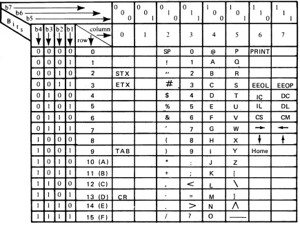
? 0-FIGURE 12. KEYBOARD CODE CHART
[image:31.612.88.523.170.505.2]b7
..
0 0 0 0 I I~
~ 0 0 1 1 0 0B. bS ... 0 I ·0 1 0 1
~i~~i~
0 12
3 4 50 0 0 0 0 SP 0 @ P
0 0 0 1 1 SOH ! 1 A 0
0 0 1 0 2 STX " 2 B R
0 0 I I 3 ETX
#
3 C S0 1 0 0 4 EOT $ 4 0 T
0 1 0 I 5 ENO % 5 E U
0 1 1 0 6 & 6
F
V0 I 1 1 7 BEL , 7 G W
I 0 0 0 8 ( 8 H
X
1 0 0 I 9 TAB EOM ) 9 I Y I 0 I 0 10 (A) SUB
*
: J Z1 0 1 1 11 (B) + ; K [
1 1 0 0 12 (C) ,
<
1
"-1 "-1 0 1 13 (D) CR
.
= M ]1 1 1 0 14 (E)
>
N
1\
1 1 1 1 15 (F)
/
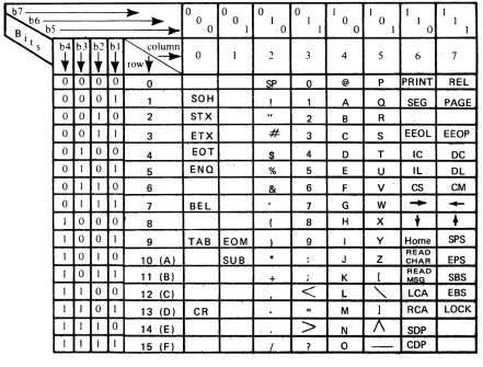
? 0-FIGURE 13. CQMMUNICATIONS CODE CHART
F or interface code sum mary, See pages 32-34.
I I
1 1
0 1
6 7
PRINT REL
SEG PAGE
E~OL EEOP
IC DC
IL OL
CS CM
...
~t
•
Home SPS READ CHAR EPS
READ SBS
MSG
LCA EBS
RCA LOCK
SOP
[image:32.612.76.517.165.500.2]KEYBOARD AND COMMUNICATIONS CODE SUMMARY
ABBREVIATION
SOH STX ETX
EDT ENG
BEL TAB
CR
EOM SUB
SP
ALPHANUMERIC CHARACTERS PR INT
REL
SEG
SUMMARY
Start of Header (address)
Display Start of Text (J.) symbol. Displays End of Text (~) symbol. Initiates message tra nsm issio n. End of Transm ission (no data) Inquire. Used with SOH command. Activates bell tone generator in keyboard. Horizontal Tab. Cursor moves to next EPS code.
Displays Carriage Return symbol. Cursor moves to first column.
End of Memory (Media).
Displays Parity Error ( . ) symbol. Space.
Displays sym bol shown on keys.
Initiates message transmission to printer. Release Lock. Releases keyboard and re-turns term inal to local.
KEYBOARD AND COMMUNICATIONS CODE SUMMARY
ABBREVIATION
BFK 1 & 2 EEOL
EEOP
IC
DC
IL
DL
CS
CM
HOME
SPS
EPS
SUMMARY
B la n k keys. In 0 perative
Erase to End of Line. Erases from cur-sor to end of line.
Erase to End of Page. Erases from cur-sor to end of page.
Insert C ha racter. I nserts a space at cu r-sor, moves follow ing characters to right. Delete Character. Deletes character at cu rsor position, follow i ng characters move to left.
Insert Line. Fills cursor line with spaces, lines below move down.
Delete Line. Deletes cursor line, lines below move up.
Clear Screen. Erases all un-protected data on screen.
Clear Memory. Fills entire memory with space codes.
Cursor Control. Cursor moves on space in direction shown.
Cursor Control. Cursor moves to Home position.
KEYBOARD AND COMMUNICATIONS CODE SUMMARY
ABBREVIATION
READ CHAR READ MSG
SBS
EBS LCA
RCA
LOCK SOP
COP
SUMMARY
Character at cursor position is read. Unprotected data from cursor to ETX or EOM is read.
Start Blink Sequence. Following char-acters will blink.
E n~ B I in k Sequence. Ends blin k sequence. Load Cu rsor Add ress. U sed by processor to position cursor.
Read Cursor Address. Transmits cursor addresses to processor.
Used by processor to lock out the keyboard. Set DATA·PANEL. Allows processor to tu rn on 1 of 16 ind icators.
INTRODUCTION
SECTION IV
THEORY OF OPERATION
NOTE: All ASCII codes referred to in this manual are in hexadecimal notation See code charts in Section V.
The Series 400 DATA-SCREEN Terminals consist of three modules: a power supply, a TV monitor and a card cage assembly. The power supply module provides all the necessary voltage inputs for the TV monitor, control and interface electronics, and oPtional functions. The standard TV monitor is a 12 inch (diagonal) solid-state re-ceiver with a P4 phosphor coated screen. The card cage accomodates up to 10 printed circuit boards. The first five contain the electronics used to operate the basic terminal. The remaining five slots house the PCB's used for the external interface and opti·onal functions.
This Section ~escribes the operCiition of the basic terminal and its internal optionsf Oper .. ation of the interface is described in the SER IAL I/O ADAPTOR SECTION and optional accessories i.e., DATA'PANEL Display, Print Adaptor, etc., in the OPTIONS Section.
The basic terminal electronics consist of five PCB's: TIMING GENERATOR, LINE MEMORY & CHARACTER GENERATOR, PAGE MEMORY, CONTROL, and COUN· TER.
The Tim ing Generator bo~rd contains a basic oscillator and several counter type frequency dividers. It provides tim ing signals for the term inal.
The Line Memory & Character Generator board stores one row of data and con· verts ASCII codes to vldf;tQ signals for the monitor. Two switches on the boar~
provide the option of displaying or not displaying the Cursor and Carriage Return sym bois.
The Page Memory board stores the entire page of data. Its contents can be read and selectively altered thrQugh the keyboard and processor communication lines.
Tht! Control board decodes incoming data and loads the result into the proper place in m em ory or perform s the specified fu nction. The Control board has two jumper wire options for enabling Auto Roll-Up and Line Feed.
The Counter board consists of three counter circuits that are, in effect, address registers containing the current addresses of the next data location, page memory location and cu rsor location.
PRINTED CIRCUIT BOARD FUNCTIONS
Model 420, 1000 Character Display, 50 characters per line x 20 lines.
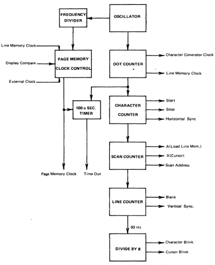
TIMING GENERATOR - Board 1. See Functional Diagram, Figure 14.
BASIC OSCILLATOR*
The oscillator frequency is determ ined as foil ows:
50 Hz 60 Hz Refresh rate
x 317 x 264 No. of horizontal scans per frame
15.84 KHz 15.84 KHz
?L..M
?L..M
No. of character tim es per scan1.01376 MHz 1.01376 MHz
~ ~ No. of dot times per character
7.09632 MHz 7.09632 MHz
DOT COUNTER
The Dot Counter divides the oscillator frequency by seven. Dot count 1 thru 5 are the displayed character and dots 6 and 7 are blanks. The count is octal 1 thru 7. Phase 1 and phase 2 clocks for the Character Generator ROM and clock for the Line Memory are generated from Dot CQunter sig-nals.
CHARACTER COUNTER
SCAN COUNTER
This 4 stage binary counter is driven by the Horizontal Sync pulse at 15.84 KHz. The cou nter is reset to zero after the cou nt of ten and therefore divides by eleven. Each scan counter cycle represents one line of displayed characters. The scans are labeled thus:
o
1-7
8
9
10
LINE COUNTER
Binary 0000 Oxxx 1000 1001 1010
Scan Display
C blank
1-7 characters
X cursor
A blank
B blank
This counter consists of a divide-by-12 counter and a divide by 2 stage. The outputs are vertical sync for the TV monitor at 60 Hz, a blanking signal during vertical retrace and a counter reset signal used on the counter board.
BLINK RATE
The 60 Hz is divided by 16 to provide a cursor blink rate of about 4 Hz. This divided by 2 to provide the character blink rate for use in the blink sequences.
PAGE MEMORY CLOCK GENERATOR
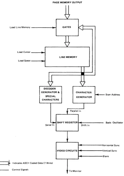
LINE MEMORY & CHARACTER GENERATOR - Board 2. See Functional Diagram, Figure 15.
LINE MEMORY
This section consists of seven MOS 50 bit dynamic shift registers operated in a bit parallel, character-serial mode. Also included are input/recirculate gates, output gates, voltage level converters, clock generator and driver circuits and load control circuits. The Line Memory stores one line of characters (50) while it is being displayed and is also used as a buffer memory during insert and delete edit functions.
During refresh the Line Memory is loaded with a line of characters from the Page Memory during each Scan A. These are then recirculated during the next 10 scans and displayed during scans 1 thru 7. The cursor code (NUL, all "O's"), is forced into the Line Memory when the Cursor Compare and Cursor Blink Rate signals are both present. The result is an alternating cur-sor symbol and displayed character at a 4 Hz rate.
During ed iting th e Line M em ory is operated at the Page M em ory rate so that data can be transferred between the mem ories. Two discrete com ponent circuits generate phase 1 and phase 2 clock pulses from the leading and trail-ing edges respectively of the input clock signal.
CHARACTER GENERATOR
The special symbols for STX, ETX, Carriage Return, Substitute and the Cur-sor are generated by TTL circuits. This data is serialized in another five bit register to compensate for the time delay normally taken thru the ROM.
The video is gated off during editing functions to prevent meaningless display on the CRT when the Line Memory is not being used for refresh.
NTSC composite video & sync is provided on a BNC connector (VIDEO OUT) on the rear panel for driving remote TV monitors.
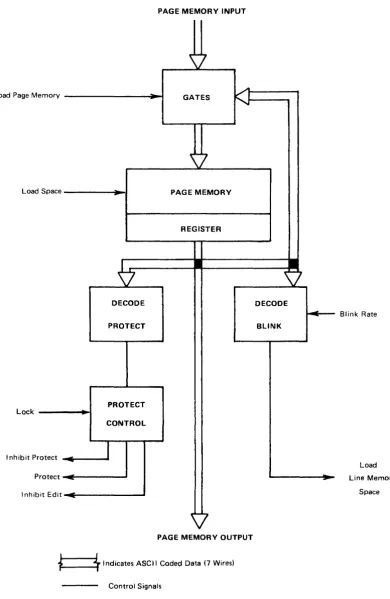
PAGE MEMORY - Board 3. See Functional Diagram, Figure 16.
PAGE MEMORY
The ,Page Memory consists of seven 1024 bit MOS serial shift registers con-nected bit-parallel, character-serial, a long with input/recircu late gates, an out, put register and clock drivers. The switching of the input gates is controlled by the interface via the control board.
Each 1024 bit shift register is actually two 512 bit registers multiplexed. Thus each clock pulse, phase 1 or phase 2, results in a new character at the out-put and a new character loaded at the inout-put. The clock rate is therefore divided by two and split into a 2 phase clock. Discrete circuit clock drivers provide the required voltage and power amplification. The output register provides properly tim ed ou tputs to the rest of th e term inal logic. Th is register adds one character to the memory making 1025 characters of stor-age.
PROTECT & BLINK CONTROL
The system is prevented from "hanging-up" in the event a programming error results in protecting the entire page, i.e., SPS at Home and no EPS in the memory. Under this condition the cursor remains at Home and the Protect function is inh ibited. At least one position must be unprotected.
Insert and delete editing functions are inhibited when there is a protect field in the memory.
A flip-flop in the blink circuit is set when the Start Blink (SBS Code - ASCII 7 B) is decoded at the page m em ory in put and the character bli n k signal is present in the high state. The Page Memory character codes are replaced by space codes in the Line Memory when the LM is loaded during Scan A. This causes the characters following the SBS code to blink on and off at a two Hz rate until an End Blink (EBS Code - ASCII 7C) is decoded causing the blink flip-flop to reset.
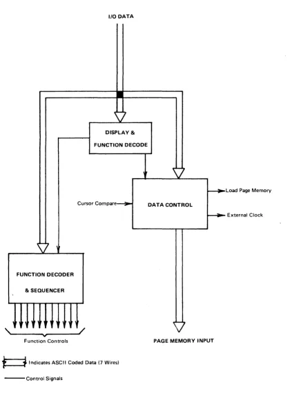
CONTROL - Board 4. See Functional Diagram, Figure 17.
All codes received by the term inal from the keyboard interface are sent from the I/O to the control board. The code is exam ined to determ ine whether it is a data or a function code. Data codes are loaded into the Page Memory at the present cursor address and the cursor is advanced one position. Func-tio n codes are decoded and the fu ncFunc-tio n is perform ed. Codes not recogn ized as data or a fu nction for th is term inal are "du m ped".
INPUT SECTION
FUNCTION DECODER
This decoder is enabled when the Function flip-flop is set. The input of a fou r bit to 1-of-16 decoder ind icates which row, 0 th ru F, the code is in and combined with column information, forms a discrete signal for each func-tion. Refer to the ASCII code chart.
ERASE FUNCTIONS - (Clear Memory, Clear Screen, Erase to End of Line and E rase to End of Page)
The CM function sends the cursor to the Home position where the erase be-gins. Format protect functions are inhibited so that the entire memory is erased. The Function flip-flop is cleared and the erase term inated by the End of Memory signal. The CS function sends the cursor to the Home position where the erase begins. Format protect functions are not inhibited so that only unprotected characters are erased. The Function flip-flop is cleared and the erase terminated by the End of Memory signal. The EEOL and EEOP functions begin the erase at the present cursor position. Format protect fu nctions are not inhibited so that only unprotected characters are erased. The cursor remains in its position. The Function flipaflop is cleared and the erase term inated at the End of Line signal for E EO L and at the End of Memory signal for EEOP.
LOAD CURSOR ADDRESS FUNCTION
When the LCA code is received a control flip-flop is set which steers the one's com plem ent of the next code received to the horizontal section of the cursor counter. At that time, the first control is cleared and a second control is set. The one's complement of the next code goes to the vertical section of the cursor counter and the second control is cleared. When either control flipeflop is set, codes can not be interpreted as data or func-tions.
INSERT AND DELETE FUNCTIONS - (Insert Line, Insert Character, Delete Line Delete Character)
INSERT AND DELETE LINE SE~UENCE
Insert and Delete Line functions follow a similar sequence. Both functions move the cursor to the beginning of the line by clearing the Cursor Hori-zontal Address Cou nter to zero. Then the Line Memory clock and video are disabled and two control flip-flops set. * The first flip-flop activates a signal that forces space codes into the Page Memory and the second controls the gating of the Page Memory clock and output to the Line Memory. At the End of Line signal the first flip-flop is cleared. The combination of the first flip-flop cleared and the second flip-flop set, gates the Line Memory output to the Page Memory input. At this point, the Line Memory and Page Memory are in series and one line of spaces has been loaded into the Page M em ory. The m em ories a re clocked together until the fu nction is term inated. * *
* A Cursor Compare signal sets the two flip-flops for the Insert Line function while an End of Memory signal is used for the Delete Line function.
** An End of Memory signal terminates the Insert Line function while a Cursor Compare signal is used for the Delete Line function.
INSERT AND DELETE CHARACTER SE~UENCE
The Insert and Delete Character functions follow a sim ilar sequence. For both functions the Line Memory clock and video are disabled and the Page Memory clock is gated to the Line Memory. The first complete (full line) Cursor Compare Vertical causes the Load Line M emory signal to go active. At the End of Line signal the data in the Line M em ory is recircu lated. At th is poi nt the two fu nctions differ:
l':lsen Character - The next Cursor Compare Vertical causes the Line Memory output to become Page Memory input. The following Cursor Compare (both vertical and horizontal) loads the Page Memory with a space at the cursor position and inhibits the Line Memory Clock one character time losing the last character in the line.
COUNTERS - Board 5. See Functional Diagram, Figure 18.
This board contains 3 binary counters and 2 comparators. All counters are organized by colum n and line i.e., 50 counts horizontally and 20 counts vertically. A vertical count pulse is generated when the horizontal section rolls over from 49 to O.
PAGE MEMORY COUNTER
This is a count up only counter which is advanced one count each time the Page Memory is clocked. It therefore contains the address of the character currently being read and loaded into the Page Memory. Since the PM is 1025 characters long, a m aster reset pulse is generated at vertical count 20 and horizontal count 24 to reset both sections to O.
DISPLAY COUNTER
This is a count up only counter which is advanced 50 counts during each Scan A and is reset to 0 during vertical retrace. It therefore contains the address of the next character to be' loaded into the Line Memory for dis-play.
CURSOR COUNTER
This is a count up, count down and directly presettable counter. It contains the address of the cursor position on the screen. Count down roll over from
o
to 49 horizontal and 0 to 19 vertical is provided by the borrow outputs which preset 49 into the horizontal counter and 19 into the vertical counter.Invalid addresses are detected and inhibit the Load Cursor Address function. An invalid address is "dumped", allowing the display. to continue in sequence.
A "Bell" signal is generated when the horizontal section goes from count 43 to 44 or the vertical section goes from count 18 to 19. This signal is used to operate the keyboard bell.
COMPARATORS
The Cursor Comparator indicates coincidence between the Page Memory Coun-ter and the Cursor CounCoun-ter for loading and reading the Page Memory and for display ing the .cu rsor.
PRINTED CIRCUIT BOARD FUNCTIONS
Model 425, 1920 Character 0 isplay, 80 characters per line X 24 lines
TIMING GENERATOR - Board 1. See Functional Diagram, Figure 14.
BASIC OSCILLATOR*
The oscillator frequency is determ ined as follows:
50 Hz 60 Hz Refresh rate
x 312 x 260 No. of horizontal scan per frame
15.60 KHz 15.60 KHz
x 102 x 102 No. of character times per scan
1.5912 MHz 1.591 2 MHz
~
L-l.
No. of dot times per character11.1384 MHz 11.1384 MHz
DOT COUNTER
The Dot Counter divides the oscillator frequency by seven. Dot counts 1 thru 5 are the displayed character and dots 6 and 7 are bianks. The count is octal 1 thru 7. Phase 1 and phase 2 clocks for the Character Generator ROM and clock for the Line Memory are generated from Dot Counter sig-nals.
CHARACTER COUNTER
SCAN COUNTER
This 4 stage decade counter is driven by the Horizontal Sync pulse at 15.6 KHz. Each scan counter cycle represents one line of displayed characters. The scans are labeled thus:
Count Binary Scan Display
0 0000 B blank
1-7 Ox xx 1-7 characters
8 1000 X cursor
9 1001 A blank
LINE COUNTER
Th is cou nter consists of a d ivid e-by-16 cou nter and a divide by 2 stage. The outputs are vertical sync for the TV monitor at 60 Hz, a blanking signal
d\Jring vertical retrace and a counter reset signal used on the counter board. It is reset to 0 at the end of count 25.
BLINK RATE
The 60 Hz is divided by 16 to provide a cursor blink rate of about 4 Hz. This is divided by 2 to provide the character blink rate used in the char-acter bl in k sequences.
PAGE MEMORY CLOCK GENERATOR
LINE MEMORY & CHARACTER GENERATOR ~ Board 2. See Functional Diagram Figure 1.5.
LINE MEMORY
Th is section consists of seven M 0 S 80 bit dynam ic sh ift registers operated in a bit-parallel, character-serial mode. Also included are input/recirculate gates, output gates, voltage level converters, clock generator and driver cir-cuits and load control circir-cuits. The Line Memory stores one line of charac-ters (80) while it is bejng displayed and is also used as a buffer memory during insert and delete edit functions,
During refresh the Line Memory is loaded with a line of characters from the Page Memory during each Scan A. These are then recirculated during the next 9 scans and displayed during scans 1 thru 7. The cursor code (NU L, all "0 'sIt), is forced into the Line M em ory when the Cu rsor Co m pare and Cursor Blink Rate signals are both present. The result is an alternating cur-sor symbol and displayed character at a 4 Hz rate.
During ed iting the Line M em ory is operated at the Page M em ory rate so that data can be transferred between the memories. Two discrete component cir-cuits generate phase 1 and phase 2 clock pulses from the leading and trailing edges respectively of the input clock signal.
CHARACTER GENERATOR
The special symbols for STX, ETX, Carriage Return, Substitute and the Cur-sor are generated by TT L circu its. Th is data is serial ized in anoth e r five bit register to compensate for the time delay normally taken thru the ROM.
The video is gated off during editing functions to prevent meaningless display on the CRT when the Line Memory is not being used for refresh.
NTSC composite video and sync is provided on a BNC connector (V IDEO OUT) on the rear panel for driving remote TV monitors.
A switch selectable option allows either normal white-on-black or inverted black-on-wh ite display.
PAGE MEMORY - Board 3. See Functional Diagram, Figure 16.
PAGE MEMORY
The Page M em ory consists of fou rteen 1024 bit M
as
serial sh ift registers connected as seven 2048 bit registers in parallel (operating in bit-parallel, character-serial mode) along with input/recirculate gates, input and output registers and clock drivers. The switch ing of the input gates is controlled by the interface via the control board.PROTECT & BLINK
A flipflop in the protect circuit is set when a Start Protect (SPS Code -ASCII 79) is decoded at the page memory input. The cursor will autoa
matically advance, UN LESS the keyboard is locked out, until the End Protect (EPS Code· ASCII 7A) is decoded causing the protect flip-flop to reset. Therefore, the field of data between the SPS and EPS posi· tions can not be altered from the keyboard.
The system is prevented from "hanging-u p" in the event a program m ing error resu Its in protecting the entire page, i.e., SPS at Hom e and no E PS in the memory. Under this condition the cursor remains at Home and the Protect function is inhibited. At least one position must be unpro-tected.
Insert and delete editing functions are inhibited when there is a protected field in the memory.
A flip-flop in the blink circuit is set when the Start Blink (SBS Code· ASCII 7B) is decoded at the page memory input and the character blink -signal rs present in the high state. The Page Memory character codes are
replaced by space codes in the Line Memory when the LM is loaded during Scan A. This caused the characters following the SBS code to blink on
and off at a two Hz rate until an End Blink (EBS Code - ASCII 7C) is decoded causing the blink flip-flop to reset.
CONTROL - Board 4. See Functional Diagram, Figure 17.
INPUT SECTION
Bits 6 & 7 of the codes com ing from the I/O are exam ined to determ ine if the code is data, columns 2 through 5 or a function, columns 0, 1, 6 & 7 of the ASCII Code Chart. The Load Register pulse from the I/O is then gated to set the Data flip·flop or Function flip·flop. If either flip·flop is set, the term inal is "busy" and no new data can be entered into the Data
Bit Register in the interface. CR, SUB, STX and ETX, & SPS, EPS, SBS, EBS, functions cause data to be forced into memory.
FUNCTION DECODER
Th is decoder is enabled when the Function flip·flop is set. The input of a four bit to 1·of·16 decoder indicates which row, 0 thru F, the code is in and combined with column information, forms a discrete signal for each function. Refer to the ASCII code chart.
ERASE FUNCTIONS - (Clear Memory, Clear Screen, Erase to End of Line and Erase to End of Page)
The CM function sends the cursor to the Home position where the erase be-gins. Format protect functions are inhibited so that the entire memory is erased. The function flip-flop is cleared and the erase term inated by the End of Memory signal. The CS function sends the cursor to the Home position where the erase begirlS. Format protect fU'nctions are not inhibited so that only unprotected characters are erased. The Function flip-flop is cleared and the erase terminated by the End of Memory signal. The EEOL and E EOP functions begin the erase at the present cursor position. For· m at protect fu nctions are not in h ibited so that on Iy unprotected ch aracters are erased. The cursor remains in its position. The F unction flip-flop is cleared and the erase term inated at the End of Line signal for E EO Land at the End of Memory signal for EEOP.
LOAD CURSOR ADDRESS FUNCTION
the cursor counter. At that time, the first control is cleared and a second control is set The one's com plim ent of the next code goes to the verti-cal section of cursor counter and the second control is cleared. When either control flipwflop is set, codes received can not be interpreted as data or fu nctions.
INSERT AND DELETE FUNCTIONS -- (Insert Line, Insert Character, Delete Line, Delete Character)
If there is a protected field anywhere in the Page Memory, the Insert and Delete functions are inhibited. The function flipwflop is cleared immediately ending the function before it begins. The following descriptions assume no protected areas.
INSERT AND DELETE LINE SEQUENCE
Insert and Delete Line functions follow a similar sequence. Both functions move the cursor to the beginning of the line by clearing the Cursor Hori-zontal Address Counter to zero. Then the Line Memory clock and video are disabled and two control flip-flops set.
*
The first flip-flop activates a signal that forces space codes into the Page Memory and the second controls the gating of the Page Memory clock and output to the Line Memory. At the End of Line signal the first flipwflop is cleared. The combination of the first flipwflop cleared and the second flip-flop set, gates the Line Memory output to the Page Memory input. At this point, the Line Memory and Page Memory are in series and one line of spaces has been loaded into the Page Memory. The memories are clocked together until the function is term inated. * ** A Cursor Compare signal sets the two flip-flops for the Insert Line function while an End of Memory signal is used for the Delete Line functions.
INSERT AND DELETE CHARACTER SEQUENCE
The Insert and Delete Character functions follow a sim ilar sequence. For both fu nctions the Line M em ory clock and video are disabled and the Page Memory clock is gated to the line Memory. The first complete (full line) Cu rsor Co m pare Vertical cau ses the Load Line M em ory signal to go active. At the End of line signal the data in the line Memory is recirculated. At This point the two functions differ:
Insert Character - The next Cursor Compare Vertical causes the Line Memory output to become Page Memory input. The following Cur-sor Compare (both vertical and horizontal) loads the Page Memory with a space at the cursor position and inhibits the Line Memory Clock one character time losing the last character in the line.
Delete Character - The next Cursor Compare Vertical causes the Line Memory output to become Page Memory input and loads the Line Memory with a sPace at the end of the line. The following Cursor Compare (both vertical and horizontal inhibits the Page Memory Clock one character time losing the deleted character.
Both functions are terminated by the next End of line signal.
'COUNTER - Board 5. See Functional Diagram, Figure 18.
Th is board contains 3 binary cou nters and 2 com parators. A II cou nters are organ ized by colu mn and I ine i.e., 80 cou nts horizontally and 24 cou nts vertically. A vertical count pulse is generated when the horizontal section rolls over from 79 to O.
PAGE MEMORY COUNTER
2049 characters long, a master reset pulse is generated at vertical count 25 and horizontal count 48 to reset both sections to O.
DISPLAY COUNTER
Th is is a cou nt upon Iy cou nter wh ich is adva nced 80 cou nts du ring each Scan A and is reset to 0 during vertical retrace. It therefore cont