0500 Display Controller
Reference Manual
(Order Number 004-02207-00)
April 1, 1984
Copyright ® 1984 Metheus Corporation 5510 N.E. Elam Young Parkway
DISCLAIMER
The information in this manual is subject to change without notice.
Me the us Corporation makes no warranty of any kind with regard to this material, including, but not limited to, the implied warranties of merchantability and fitness for a particu-lar purpose. Metheus Corporation assumes no responsibility for any errors that may appear in this manual. Metheus Corpora-tion makes no commitment to update nor to keep current the information contained in this document.
Metheus Corporation assumes no responsibility for the use of any circuitry other than circuitry embodied in a Metheus pro-duct. No other circuit patent licenses are implied.
Metheus software products are copyrighted by and shall remain the property of Metheus Corporation. Use, duplication, or dis-closure is subject to restrictions stated in your Metheus software license.
No part of this document may be copied or reproduced in any form or by any means without the prior written consent of Metheus Corporation.
Revision Revision History Date Number
-00 First Issue. Describes the Q500 Display 4/84 Controller Instructions for version 2.3 microcode.
This equipment complies with the requirements in part 15 of FCC rules for a class A computing device. Operation of this equipment in a residential area may cause unacceptable interference to radio and TV reception requiring the operator to take whatever steps are necessary to correct interference.
i
PREFACE
This manual describes the instruction set for the 0500 display controller. Primarily, this is a reference manual and requires a high degree of experience with interactive graphics to under-stand. The first two chapters, however, present some basic concepts about graphics systems in general and the 0500 in particular.
The reference section, Chapters 5 through 11, divides the instructions into seven functional groups. Within each group, instructions are listed alphabetically. Chapter 4 introduces and describes the organization of this reference section.
Chapters at a Glance
Chapter 1 - Introduction to the 0500
Briefly discusses some basic concepts about interactive graphics systems.
Chapter 2 - Q500 Graphics
Provides system-specific details like addressing and memory size. Introduces several instructions and their function. Contains a list of all instructions and the chapter that describes them.
Chapter 3 - Installation Instructions
Provides step-by-step instructions for installing and using the GRAFIN board, and for cabling the 0500 to the monitor and the host computer.
Chapter 4 - Using the Instruction Reference Chapters
Introduces and explains how to effectively use the chapters that describe each group of instructions.
Chapters 5 through 11
Describes seven groups of instructions that control the 0500 Display Controller. Instructions in each group are alphabetically arranged by name.
Appendix A
Lists the conversions between ASCII, decimal, octal, and hexadecimal.
r
CONTENTS
CHAPTER 1
Introduction to the Q500
The Q510 1-2 The 0530 1-2 Speed 1-2 Reliability 1-2 Software and Hardware Support 1-3
CHAPTER 2 0500 Graphics
Display Units 2-1 Coordinate Addresses 2-2
lines.. Rectangles.. Arcs,, and Polygons 2-3
Pointers 2-4 Pan 2-5 Raster-Ops 2-5 0530 Folded Mode 2-5
CHAPTER 3
Installation Instructions
Selecting GRAFIN Data Rates 3-1 Installing the Interface 3-6 Replacing the Fuse 3-6 Connecting to the Monitor 3-7 Connecting to the Computer 3-7
Connecting to Power 3-7
CHAPTER 4
Using the Instruction Reference Chapters
Group Descriptions 4-1
CHAPTER 5
Display-Pointer-Move Instructions
CHAPTER 8 Display-Control Instructions BLANK 8-2 BLINK 8-4 CMAP 8-6 CURS 8-8 PPAN 8-10 SZCUR 8-12 CHAPTER 9 Data-Transfer Instructions GRAFIN 9-2 PIXBLT 9-7 RDR 9-9 RPIXEL 9-11 WPIXEI 9-13 vyRR 9-ID CHAPTER 10 Utility Instructions DFAULT 10-2 INIT 10-4 INQ 10-5 LDF0NT 10-7 LDPAT 10-9 READ C0NF 10-11 SIGREAD 10-12 STOCH 10-13 CHAPTER 11 Folded-Mode Instructions BANK 11-2 0VMAP 11-4 SELRES 11-7 XBARLD 11-9 APPENDIX A
FIGURES
NUMBER FIGURE TITLE PAGE 1-1. The Q500 Display Controller and Monitor 1-1
2-1. Creating Images With Pixel Combinations 2-2
2-2. Coordinate Addresses 2-3 3-4. Removing the Top Cover 3-2 3-2. Removing the Host and
GRAFIN Interface Boards 3-3 3-3. Locating the Data Transfer Switch
on the GRAFIN Board 3-4 3-4. Connecting the Monitor to the Back Panel 3-7
5-1. Moving the PI Pointer 5-3 5-2. Moving the P2 Pointer 5-5 5-3. Nested Polygons Created with POLYY 5-8
5-4. Nested Polygons Created with POLYV
andPOLYM 5-8 5-5. Creating Two Open Polygons Using POLYM 5-11
5-6. Adding Vertices with POLYV 5-16 5-7. Moving P i to a Relative Location 5-19 5-8. Moving P2 to a Relative Location 5-22 6-1. P i Set to a Different Color than the
Inner Boundary 6-3 6-2. P i Set Between Boundaries of
Two Different Colors 6-3 6-3. Filling to the Outer Boundary with AFILL2 6-5
6-4. Drawing an Arc 6-9 6-5. Typing Characters on the Screen 6-11
6-6. Drawing a Line in the Complement Color 6-15
6-7. Drawing a Line 6-17 6-8. FLASH-filling a Rectangle 6-19
6-9. Filling a Polygon 6-22 6-10. Outlining a Polygon 6-24 6-11. Drawing a Rectangle Outline 6-26
6-12. Filling a Rectangle 6-28 7-1. Loading the Raster-Op Comparator Array 7-9
7-2. Default Drawing and Filling Patterns 7-14 7-3. The SET COLOR Index to the
Default Color Map 7-24 7-4. Selecting the Orientation of Text 7-26
TABLES
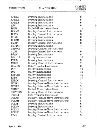
NUMBER TABLE TITLE PAGE 2-1. 0500 Instructions Listed Alphabetically 2-7
3-1. Data Rate Selection 3-5
7-1. Drawing Modes 7-12
7-2. Data Flow Control 7-16 7-3. Opl and 0p2 Assignments 7-17
7-4. ALU Functions 7-17 7-5. Drawing Raster-Ops 7-19 7-6. PIXBLT Raster-Ops 7-19 7-7. Meaning of Bits in the Orientation Byte 7-25
9-1. 0500 Status Message Format 9-3
10-1. INQ Parameters 10-6 A-l. Code Conversion Chart A-l
{
CHAPTER 1
[image:13.612.135.505.133.425.2]INTRODUCTION TO THE 0500
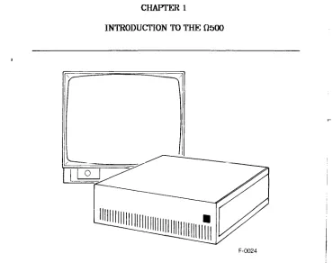
Figure 1-1. The 0500 Display Controller and Monitor
The 0500 Display Controller, shown in Figure 1-1, is a high-resolution, high-performance color graphics device. It translates instructions from a host computer system into color and timing signals for a display monitor.
Introduction
The 0510
The 0510 Display Controller's graphics memory provides a reso-lution of 1280 x 1024 points which, when coupled with a monitor capable of this same high resolution, provides a highly-detailed display.
The 0510 memory is organized into eight bit-planes. This organization places 256 colors in the display color map at one time. These colors are dynamically selectable from a palette of 16.7 million color choices.
The 0530
The 0530 Display Controller's graphics memory can be switched between high and low resolution in software. High-resolution applications operate in the normal 1280 x 1024 configuration. For applications that require more color depth and lower reso-lution, the 0530 can be operates in folded mode. Folded mode provides 32 bit-planes, each with 640 x 512 resolution.
Speed
The 0500 writes four to ten times faster than other system because it uses a bipolar bit-slice processor. Faster display speed means an easier and friendlier system to work with. No more long waits for graphics changes to appear.
Reliability
Introduction
Software and Hardware Support
The AXIA Graphics Package option, available for the host com-puter, provides software that supports the 0500 Systems. The AXIA Graphics Package is described in a separate manual. Special instructions support graphics input devices, such as graphics tablets and bit-pads. These devices simply plug into the serial connector on the 0500 back panel.
CHAPTER 2 0500 GRAPHICS
This chapter briefly introduces the terms used in this manual and the instructions found in the reference section, Chapters 5 through 11. Table 2-1, at the end of this chapter, lists all the instructions with the chapter number and title that describes them. This chapter describes several elements of computer graphics, listed below, that are specific to the 0500 Display Controllers.
o Display units
o Coordinate addresses
o Lines, rectangles, arcs, and polygons o Pointers
o Pan o Raster-ops o 0530 folded mode
Display Units
In the 0500 Systems, the pixel (picture element) is the basic element of graphic display. Pixels represent a single address-able point in graphic memory and a single displayaddress-able point on the monitor screen. Graphic memory resolution (the range of addressable pixels) is 1280 in the x axis by 1024 in the y axis; That is over one million addressable points. All display images are created by writing combinations of adjoining pixels. (See Figure 2-1.)
fthOO Graphics
F-0025
Figure 2-1. Creating Images With Pixel Combinations
Coordinate Addresses
The Q500 devices describe locations on the screen with coordi-nate addresses. Each point, or pixel, in graphic memory is represented by a unique coordinate address. Pixel addresses consists of an x value and a y value representing the point where the x and y axes meet.
0500 Graphics
cn
x <
>
((0,0) ( 1 2 7 9 ^
/n -lAOON
1 1— \J£.0) (1279,1023)j
X Axis
F-0026
Figure 2-2. Coordinate Addresses
In the coordinate system, the upper left corner of the screen and in graphic memory represents (0x,0y). The lower right corner represents (l279x, 1023y). Therefore, x address values increase from left to right; y address values increase from the top to bottom. Memory and screen coordinates are the same. Although two 8-bit bytes are transmitted between the host and the display controller for each coordinate address, only 11 bits represent each x coordinate value and 10 represent each y coordinate value. A complete address specification consists of four 8-bit bytes: low-x, high-x, low-y, and high-y. The reference chapters in this manual abbreviate these address specifications to lox, hix, loy, and hiy and explain which bits are significant.
lanes, Rectangles, Arcs, and Polygons
Pixels combine in many ways to create graphic images. The basic display elements are the line (or vector), the rectangle, the arc, and the polygon.
fi500 Graphics
A line, or vector, is a sequence of adjoining pixels extended between two points on the display. A line can be solid or dashed. A solid line contains pixels all written in the same color. A dashed line contains pixels written in the current drawing color interspersed with spaces.
A rectangle is any four-sided figure with 90-degree angles, including a square, where the sides are parallel to the x and y axes. Only two corner points are required to define a rectangle. Rectangles can be outlined, solidly filled, pattern-filled, or filled then outlined in another color. A number of drawing instruc-tions, described in Chapter 6, create the various rectangle styles.
An arc is a curved line. Like any line, it can be solid or dashed. Continuing an arc until the end meets the starting point creates a circle.
A polygon is any multi-sided figure. Polygons are created by defining their vertex points using two drawing instructions, described in Chapter 6, called POLYY and POLYM. Like rectan-gles, polygons can be outlined and filled using two more draw-ing instructions, POLYO and POLYF.
Pointers
0500 Graphics
Pan
The PPAN instruction, described in Chapter 8, relocates the display on the screen vertically or horizontally, panning like a camera. Images pan in fixed blocks measuring 40 pixels hor-izontally and 16 pixels vertically. When the Q530 is operated in folded mode, images pan 20 pixels horizontally.
Raster-Ops
Raster operation instructions (see RASTOP in Chapter 7) condi-tionally modify pixels. Raster-ops affect lines and blocks of pix-els logically or arithmetically. For example, a logical raster-op can exclusively OR (X0R) the pixels in a rectangle to comple-ment their color. An arithmetic raster-op can add color values to pixels as they are transferred from their source to their des-tination. Chapter 9 contains more information on the PIXBLT instruction (Pixel Block Transfer).
The RASTOP instruction specifies the type of raster operation (logical or arithmetical) and enables the Raster-Op Comparator (ROC). The ROC is an array of bits that conditionally prevent or allow data tranfers for that pixel location. The LDR0C instruc-tion, in Chapter 7, loads values into the ROC.
0530 Folded Mode
The 0530 Display Controller has two screen resolutions: high resolution (1280 * 1024 * 8) and folded mode (640 * 512 * 32). When high resolution is selected, the 8 bit-planes allow 256 colors. In folded mode, the memory is reconfigured to provide 32 bit-planes. These 32 planes are divided into four banks of 8 planes each: bankO, bankl, bank2, and bank3.
These four banks can be individually routed to any of the color lookup tables (the palette). For instance, routing one bank to the red lookup table, one bank to the green, and another bank to the blue creates a 24-bit-deep image. Another way to achieve this image is by storing four sets of 8-bit images in the banks (one image per bank). To display a particular image,
fi500 Graphics
route the appropriate bank to all three color lookup tables. Additionally, plane 0 of both bankS and bank3 can be used as overlay planes. When the overlay lookup-table is enabled, bits set in an overlay plane take priority over colors in the memory banks. Either or both of the two overlay planes may be enabled.
In folded mode, operations such as setting the current drawing color or write mask, take place in a selected bank of 8 planes. Other banks can also perform these operations independently. Each bank remembers its last drawing color and write mask. Selecting a new bank restores its previous color and write mask.
A jumper on the display controller board selects the default screen resolution, normal or folded. However, screen resolution can dynamically change using (Since the horizontal scanning frequency changes between 65.7 KHz and 33KHz, the monitor may need adjustment. Few monitors can run at both frequen-cies.)
0500 Graphics
Table 2-1. 0500 Instructions Listed Alphabetically
INSTRUCTION CHAPTER TITLE NUMBER
AFILL1 Drawing Instructions 6 AFILL2 Drawing Instructions 6 AFILL3 Drawing Instructions 6 ARC Drawing Instructions 6 BANK Folded-Mode Instructions 11 BLANK Display-Control Instructions 8 BLINK Display-Control Instructions 8 CHAR Drawing Instructions 6 CLEAR Drawing Instructions 6 CMAP Display-Control Instructions 8 CMPDR Drawing Instructions 7 CSPACE Drawing-Control Instructions 7 CURS Display-Control Instructions 8 DRAW Drawing Instructions 6 DFAULT Utility Instructions 10 FFILL Drawing Instructions 6 FSIZE Drawing-Control Instructions 7 GRAFIN Data-Transfer Instruction 9 INIT Utility Instructions 10 INQ Utility Instructions 10 LDFONT Utility Instructions 10 LDPAT Utility Instructions 10 LDROC Drawing-Control Instructions 7 MOVPl Display-Pointer-Move Instructions 5 M0VP2 Display-Pointer-Move Instructions 5 OVMAP Folded-Mode Instructions 11 PATTERN Drawing-Control Instructions 7 PDCBLT Data-Transfer Instruction 9 POLYC Display-Pointer-Move Instructions 5 POLYM Display-Pointer-Move Instructions 5 POLYF Drawing Instructions 6 POLYO Drawing Instructions 6 POLYS Display-Pointer-Move Instructions 5 POLYV Display-Pointer-Move Instructions 5 PPAN Display-Control Instructions 8
fi500 Graphics
Table 2-1. Q500 Instructions Listed Alphabetically
INSTRUCTION CHAPTER TITLE NulffiER
CHAPTER 3
INSTALLATION INSTRUCTIONS
After unpacking the Q500, place it in a location that provides at least two inches of air space around the top and sides for cool-ing. Then, before operating the Q500, read this chapter. It explains how to connect the QoOO system to your hardware. Specifically, the instructions in this chapter describe:
o o o o o o
CAUTION
Only qualified service personnel should attempt any procedure where the covers m u s t be removed. Read and follow the installation instructions carefully. Failure to install the Q500
properly could result in improper operation or equipment damage.
Selecting GRAFIN Data Rates
GRAFIN interface boards are set at the factory for 9600 baud. If you need to change this setting, follow these instructions.
Selecting GRAFIN data rates Installing the interface Replacing the fuse
Connecting to the monitor Connecting to the computer Connecting to power
Installation Instructions
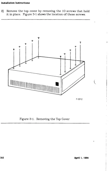
[image:26.612.145.510.128.699.2]2) Remove the top cover by removing the 10 screws that hold it in place. Figure 3-1 shows the location of these screws.
Installation Instructions
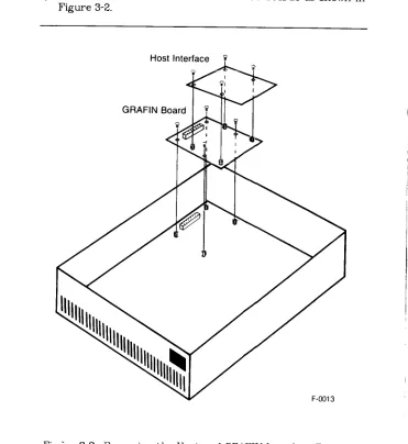
[image:27.612.130.501.165.569.2]3) Remove the GRAFIN and host interface boards as shown in Figure 3-2.
Figure 3-2. Removing the Host and GRAFIN Interface Boards
Installation Instructions
4) Find the 8-position switch near the center of the GRAFIN board. Four positions, numbered 1 through 4 in Figure 3-3, select the transfer rates. This figure shows the default switch positions selecting 9600 baud.
Interface Board Connector
Eight-position Switch set for 9600 Baud
Tablet .Cable
Connector
1 2 3 4 5 6 7 8 Off Off
F-0014
Figure 3-3. Locating the Data Transfer Switch on the GRAFIN Board
Installation Instructions
Table 3-1. Data Rate Selection BAUD SWITCH SETTINGS
4 3 2 1
unused 1 1 1
19.2K 1 1 0
9600 1 0 1
7200 1 0 0
4800 0 1 1
3600 0 1 0
2400 0 0 1
1800 0 0 0
1200 0 1 1 1
600 0 1 1 0
300 0 1 0 1
150 0 1 0 0
134.5 0 0 1 1
110 0 0 1 0
75 0 0 0 1
50 0 0 0 0
NOTE: Q=OfT, l=On
6) Switch 5 determines resolution format. When set in the 0 (off) position, the GTCO binary high resolution format is selected. The 1 (on) position selects the Summagraphics Bit-Pad format. (Refer to the tablet manual for compatibil-ity information.)
Installation Instructions
7) After changing switch positions, replace boards, the top cover, and the power cord.
Installing the Interface
In most cases, the interface is installed at the factory. If it is necessary to install an interface after receiving the 0500, refer to the Operator's Manual for that interface for installation information.
Replacing the Fuse
The line fuse inserts into the back panel of the Q500. Replace the fuse by first disconnecting power, then removing the fuse cover. Remove the fuse and replace it with one of the same value. Figure 3-4 shows the location of the fuse.
WARNING
Never change f u s e s while the Q500 i s connected to the power source. Always disconnect the power cord first to prevent equipment damage and personal injury.
CAUTION
Installation Instructions
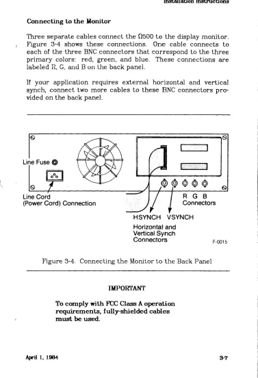
Connecting to the Monitor
[image:31.612.121.498.134.686.2]Three separate cables connect the flSOO to the display monitor. Figure 3-4 shows these connections. One cable connects to each of the three BNC connectors that correspond to the three primary colors: red, green, and blue. These connections are labeled R, G, and B on the back panel.
If your application requires external horizontal and vertical synch, connect two more cables to these BNC connectors pro-vided on the back panel.
Horizontal and Vertical Synch Connectors
Figure 3-4. Connecting the Monitor to the Back Panel
IMPORTANT
To comply with FCC Class A operation requirements, fully-shielded cables m u s t be used.
Installation Instructions
Connecting to the Computer
Refer to the Operator's Manual for the 0500 interface you are using for connection information.
Connecting to Power
After all installation procedures have been followed, connect a
power cord to the Q500 back-panel connector, then connect to an appropriate power source.
CHAPTER 4
USING THE INSTRUCTION REFERENCE CHAPTERS
Chapters 5 through 11 describe the instructions that control the graphics functions of the Q500 system. These instructions are divided into seven groups, listed below:
o Display-Pointer-Move Instructions o Drawing Instructions
o Drawing-Control Instructions o Display-Control Instructions o Data-Transfer Instructions o Utility Instructions
o Folded-Mode Instructions
To make instructions easy to find and understand, each one appears in a standard format. Also, within each group, instruc-tions appear in alphabetical order by instruction name. Table 2-1 contains all the instruction names in order with the number and title of the chapter where they appear.
These chapters use examples written in both hexadecimal and decimal. To distinguish between them, hexadecimal numbers are followed with the letter h, and decimal numbers are fol-lowed with the letter t.
Group Descriptions
The first group describes the instructions that position pointers. Positioning the display pointers is basic to many graphics actions, such as drawing lines, rectangles, arcs, or polygons. The Display Pointer Move instructions are described in Section 4.
The next group of instructions use the pointers to create images on the monitor screen. Drawing Instructions draw vec-tors, draw rectangles, and fill objects.
Using the Instruction Reference Chapters
figures are drawn and displayed. Drawing-Control Instructions set the environmental parameters for the Drawing Instructions. For example, they select the drawing colors and patterns, and the size and orientation of characters. Display-Control Instruc-tions define the colors for the color map and select the Pan ori-gin.
Data-Transfer Instructions transfer graphics data between the fi500 and the host system, as well as from one display position to another.
The Utility Instructions provide a number of non-graphic func-tions. They report the status of the system and control special functions like SYNCH (used in animation, for instance), and the on-board signature analyzer used for troubleshooting.
CHAPTER b
DISPLAY-POINTER-MOVE INSTRUCTIONS
The instructions in this chapter control the position of the display pointers. Pointers define the coordinate position of lines, polygons, and text.
o MOVP1 - Moves pointer P i to an absolute coordinate o MOVP2 - Moves pointer P2 to an absolute coordinate o POLYC - Closes a polygon definition
o POLYM - Moves pointer P i to a polygon vertex o POLYS - Starts a polygon definition
o POLYV - Adds a vertex to a polygon
I&splay Pointer-Move Instructions
M0VP1
Moves pointer P i to an absolute coordinate
Instruction Format HEX 52 lox hix loy hiy
DECIMAL: 82 x y
ASCII: R lox hix loy hiy
Input Arguments
lox the low-order eight bits of the eleven bits required to define the x coordinate value
hix only the three low-order bits of this byte are used; these three bits set the three high-order bits of the eleven bits required to define the x coordinate value loy the low-order eight bits of the ten bits required to
define the y coordinate value
hiy only the two low-order bits of this byte are used; these two bits set the two high-order bits of the ten bits required to define the y coordinate value
Outputs
None
Description
Dispiay Pomter4f ov e Instructions
Range
The allowable range for the x coordinate data is 0 through I279t, and for the y coordinate data is 0 through 1023t.
Special Considerations
None
Example
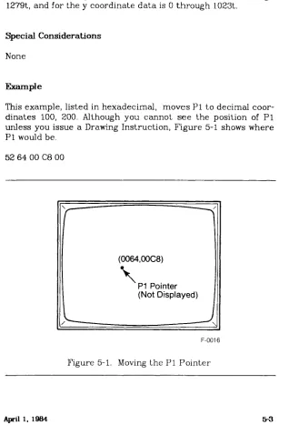
This example, listed in hexadecimal, moves Pi to decimal coor-dinates 100, 200. Although you cannot see the position of P i unless you issue a Drawing Instruction, Figure 5-1 shows where P i would be.
52 64 00 C8 00
f
—
\(0064,00C8)
\
P1 Pointer(Not Displayed)
> - —
j \ [image:37.612.160.489.190.679.2]F-0016
Figure 5-1. Moving the Pi Pointer
I&splay Pointer-Move Instructions
M0VP2
Moves pointer P2 to an absolute coordinate
Instruction Format HEX: 53 lox hix loy hiy
DECIMAL: 83 x y
ASCII: S lox hix loy hiy
Input Arguments
lox the low-order eight bits of the eleven bits required to define the x coordinate value
hix only the three low-order bits of this byte are used; these three bits set the three high-order bits of the eleven bits required to define the x coordinate value loy the low-order eight bits of the ten bits required to
define the y coordinate value
hiy only the two low-order bits of this byte are used; these two bits set the two high-order bits of the ten bits required to define the y coordinate value
Outputs
None
Description
DispLay-Fointer-Move Instructions
Range
The allowable range for the x coordinate data is 0 through I279t, and for the y coordinate data is 0 through 1023t.
Special Considerations
None
Example
This example, listed in hexadecimal, moves P2 to absolute decimal coordinates 200, 300. Although you cannot see the position of P2 unless you issue a Drawing Instruction, Figure 5-2 shows where P2 would be.
53 C8 00 2C 01
(
—
(00C8,012C) \
P2 Pointer (Not Displayed)
\
[image:39.612.143.499.212.682.2]F-0017
Figure 5-2. Moving the P2 Pointer
Display-Pointer-Move Instructions
POLYC
Closes a polygon definition
Instruction Format HEX: 44
DECIMAL" 68 ASCII: D
Input Arguments
None
Outputs
None
Description
This instruction closes, or ends, a polygon definition opened with the POLYS instruction. It also serves as a delimiter used to concatenate polygons. The connecting primitive will be an automatically generated move to the following vertex group. This move will not be overwritten after the polygon fill.
Range
Does not apply
Special Considerations
I&splay Pointer-Move Instructions
Use caution when following a POLYC command with POLYM. Moving the pointer with POLYM before the polygon definition is closed causes undefined results.
Example
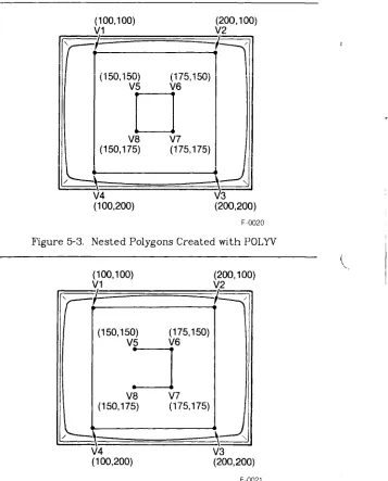
This example shows two sets of instructions in hexadecimal. Both draw two rectangles, one inside the other. The first set of instructions opens the polygon definition, defines eight ver-tices, closes the definition, then outlines them. Figure 5-3 shows the results. The next set of instructions also draws two rectangles using the same coordinates, but moves the pointer to the fifth vertex rather than defines it. Figure 5-4 shows the open inner figure that results.
56 Start the polygon definition (POLYS) 57 64 00 64 00 Define VI at 100,lOOt (POLYV) 57 C8 00 64 00 Define V2 at 200, lOOt
57 C8 00 C8 00 Define V3 at 200,200t 57 64 00 C8 00 Define V4 at 100,200t
44 Close the polygon definition (POLYC) 57 96 00 96 00 Define V5 at 150,150t (POLYV) 57 AF 00 96 00 Define V6 at 175,150t
57 AF 00 AF 00 Define V7 at 175,175t 57 96 00 AF 00 Define V8 at 150,175t
66 Outline the polygons (POLYO)
56 Start the polygon definition (POLYS) 57 64 00 64 00 Define VI at 100,100t (POLYV) 57 C8 00 64 00 Define V2 at 200,100t
57 C8 00 C8 00 Define V3 at 200,200t 57 64 00 C8 00 Define V4 at 100,200t
44 Close the polygon definition (POLYC) 45 96 00 96 00 Move to V5, 150,150t (POLYM) 57 AF 00 96 00 Define V6 at 175,150t
57 AF 00 AF 00 Define V7 at 175,175t 57 96 00 AF 00 Define V8 at 150,175t
66 Outline the polygons (POLYO)
ULspiay-rointer-Move Instructions
(100,100) VI
(150,150) V5
V4 (100,200)
(200,100)
V2
(175,150)
V6
V8 V7 (150,175) (175,175)
3 (200,200)
[image:42.612.148.505.161.604.2]F-0020
Figure 5-3. Nested Polygons Created with POLYV
(100,100)
V1 V2 (200,100)
(150,150) (175,150)
V5 V6
V8 Ml
(150,175) (175,175)
V4
(100,200) V3 (200,200)
F-0021
Dispiay-roint er-M ove Instructions
POLYM
Moves pointer P i to a polygon vertex
Instruction Format HEX: 45 lox hix loy hiy
DECIMAL: 69 x y
ASCII: E lox hix loy hiy
Input Arguments
lox the low-order eight bits of the eleven bits required to define the x coordinate
hix only the three low-order bits are used; these three bits set the three high-order bits required to define the x coordinate
loy the low-order eight bits of the ten bits required to define the y coordinate
hiy only the two low-order bits are used; these two bits set the two high-order bits required to define the y coordinate
Outputs
None
Description
Adding a vertex to the polygon data structure with POLYM moves the pointer the last x,y point. The resulting vector is not drawn during a POLYO, but is filled during a POLYF. This primi-tive is useful for clipped polygons when clipped regions align with viewport boundaries.
Display-Pointer-Move Instructions
Range
The allowable range for coordinate data is 0 to I279t for x and 0 to 1023t for y.
Special Considerations
Following a POLYC or POLYS with a POLYM instruction causes the pointer to move after the polygon definition is finished and can cause undefined results.
Example
This example, listed in hexadecimal, draws two polygons using the same coordinates. The first set of instructions, however, defines two vertices then two moves while the second set of instructions defines a move, then two vertices, then a move again. Figure 5-5 shows the differences between the polygons after outlining. In both cases, the rectangles will fill identically.
56
57 64 00 64 00 57 C8 00 64 00 45 C8 00 C8 00 45 64 00 C8 00 66
56
45 64 00 64 00 57 C8 00 64 00 57 C8 00 C8 00 45 64 00 C8 00 66
Start a polygon definition (POLYS) Define VI at 100,100t (POLYV) Define V2 at 200,100t
Move pointer to V3, 200,200t (POLYM) Move pointer to V4, 100,200t
Outline the polygon (POLYO) Start a polygon definition (POLYS) Move pointer to Vl, 100, lOOt (POLYM) Define V2 at 200,100t (POLYV)
Define V3 at 200,200t
Dispiay-Pointer-M ove Instructions
(100,100)
V1 V2 (200,100)
V4
(100,200) V3 (200,200)
(100,100) V1
V4 (100,200)
(200,100) V2
V3
(200,200)
F-0022
Figure 5-5. Creating Two Open Polygons Using POLYM
Di spl ay-Poi n ter-Move In st.nintions
POLYS
Starts a polygon definition
Instruction Format HEX:
56
DECIMAL:
86
ASCII:
V
Input Arguments
None
Outputs
None
Description
When it receives the POLYS instruction, the display controller begins constructing a new polygon, using the polygon vertices defined with succeeding POLYV instructions. Each POLYV in-struction adds another vertex to the new polygon.
DispLay-Fointer-Move Instructions
Range
Does not apply
Special Considerations
The POLYS instruction directs the display controller to build a new polygon but takes no display action on its own. The POLYV instruction adds vertices to the new polygon while the polygon remains in memory. The POLYO or POLYF instructions display the figure.
I&splay Pointer-Move Instructions
POLYV
Adds a vertex to a polygon
Instruction Format HEX: 57 lox hix loy hiy
DECIMAL- 87 x y
ASCII: W lox hix loy hiy
Input Arguments
lox the low-order eight bits of the eleven bits required to define the x coordinate value
hix only the three low-order bits of this byte are used; these three bits set the three high-order bits of the eleven bits required to define the x coordinate value loy the low-order eight bits of the ten bits required to
define the y coordinate value
hiy only the two low-order bits of this byte are used; these two bits set the two high-order bits of the ten bits re-quired to define the y coordinate
Outputs
None
Description
This instruction adds each vertex to the polygon started with the POLYS instruction. Four bytes immediately following the opcode define the coordinate for each vertex.
DispLay-Fointer-Move Instructions
Range
The allowable range for x coordinate d a t a is 0 to I279t, and for y coordinate data is 0 to 1023t. The maximum number of po-lygon vertices is at least:
POLYO: 2000t
POLYF: 36Ot (See POLYF instruction.)
Special Considerations
No display action takes place on the monitor during polygon construction. Once all vertices are defined, the polygon is filled using the POLYF Drawing Instruction, outlined using the POLYO Drawing Instruction, or filled and outlined in another color us-ing both instructions.
Example
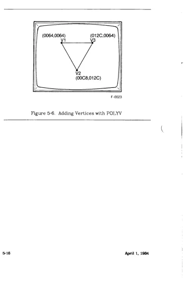
This example, listed in hexadecimal, creates a triangle using the POLYS and POLYV instructions, then outlines it with a PO-LYO instruction and fills it with a POLYF instruction. Figure 5-6 shows the outlined polygon.
56 Start a polygon definition (POLYS) 57 64 00 64 00 Define VI at lOO.lOOt (POLYV) 57 C8 00 2C 01 Define V2 at 200,300t
57 2C 01 64 00 Define V3 at 300,100t
66 Outline the polygon (POLYO) 67 Fill the polygon (POLYF)
Display Pointer Move Instructions
[image:50.612.135.506.140.716.2]F-0023
Dispiay-Fointer-M ove Instructions
RM0VP1
Moves pointer P i to a relative coordinate
Instruction Format HEX:
54 lox hix loy hiy
DECIMAL:
84 x y
ASCII:
T lox hix loy hiy
Input Arguments
lox the low-order eight bits of the 12 bits required to define the 2's complement x coordinate move
hix only the four low-order bits of this byte are used; these four bits set the four high-order bits of the 12
bits required to define the x coordinate move; note that 12-bit 2's complement arithmetic is used for defining relative moves; positive or negative move directions are allowed, depending on the 2's comple-ment number assigned
loy the low-order eight bits of the 12 bits required to define the 2's complement y coordinate move
hiy only the four low-order bits of this byte are used; these four bits set the four high-order bits of the 12 bits required to define the y coordinate move; note that 12-bit 2's complement arithmetic is used for defining relative moves; positive or negative move directions are allowed, depending on the 2's comple-ment number assigned
Outputs
None
IHspiay-Pointer-Move Instructions
Description
This instruction moves Pi relative to its present position, by the specified coordinate distances. Four bytes immediately fol-lowing the opcode define the relative distance. They form a 12-bit 2's complement argument for x and y.
Range
The allowable range of arguments for the x and y coordinate move is -2048t to +2047t. The values are assigned in 12-bit 2's complement. Following a relative move, x m u s t be between 0 and I279t, and y must be between 0 and 1023t.
Special Considerations
None
Example
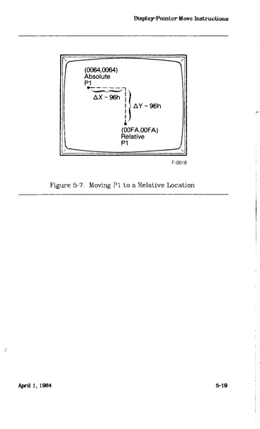
This example, listed in hexadecimal, moves the pointer P i to an absolute decimal location (100,100) then moves Pi, relative to that position, to decimal coordinates 250,250. Figure 5-7 shows the positions of Pi.
Display-Pointer^ ove Instructions
(0064,0064) Absolute P1
A Y = 96h
(00FA,00FA) Relative P1
[image:53.612.136.503.106.710.2]F-0018
Figure 5-7. Moving P i to a Relative Location
Display-Poiriter-Move Instructions
RM0VP2
Moves pointer P2 to a relative coordinate
Instruction Format HEX: 55 lox hix loy hiy
DECIMAL: 85 x y
ASCII: U lox hix loy hiy
Input Arguments
lox the low-order eight bits of the 12 bits required to define the 2's complement x coordinate move
hix only the four low-order bits of this byte are used; these four bits set the four high-order bits of the 12 bits required to define the x coordinate move; note that 12-bit 2's complement arithmetic is used for defining relative moves; positive or negative move directions are allowed, depending on the 2's comple-ment number assigned
loy the low-order eight bits of the 12 bits required to define the 2's complement y coordinate move
hiy only the four low-order bits of this byte are used; these four bits set the four high-order bits of the 12 bits required to define the y coordinate move; note that 12-bit 2's complement arithmetic is used for defining relative moves; positive or negative move directions are allowed, depending on the 2's comple-ment number assigned
Outputs
Displ ay-Point er™ ove Instructions
Description
This instruction moves P2 by the specified increment, relative to the present position of P L Four bytes immediately following the opcode define the relative distance in each direction. They form a 12-bit 2's complement argument for x and y.
Range
The allowable range of arguments for the x and y coordinate move is -2048t to +2047t. The values are assigned in 12-bit 2's complement. Following a relative move, x must be between 0 and I279t, and y must be between 0 and 1023t.
Special Considerations
None
Example
This example, listed in hexadecimal, moves the pointer P2 to a position relative to P i which is currently located at 250,250. Therefore, after this example, P2 will be at location 350,350 which is (250 + 100)x, (250 +100)y. Figure 5-8 shows the loca-tions of PI and P2.
55 64 00 64 00
ULspiay-rointer-Move Instructions
r
Current P1 (250,250)
P2 - Relative to P1 (250 + 100), (250 + 100)
[image:56.612.144.507.143.717.2]F-0019
CHAPTER 6 DRAWING INSTRUCTIONS
The Drawing Instructions display graphic images on the moni-tor. The instructions in this chapter use the display pointers (PI and P2) to draw lines, characters, and arcs, and to outline and fill polygons in a variety of colors.
o AFTLL1 - Fills a random area with the current color o AFILL2 - Fills a random area to a specific color o AF1LL3 - Fills a random area with a new color o ARC - Draws an arc or circle
o CHAR - Draws a character o CLEAR - Clears image memory
o COMPDR - Draws a vector in the complement color o DRAW - Draws a vector
o FF1LL - FLASH-fills a rectangle o POLYF - Fills a polygon o POLYO - Outlines a polygon o RECTI - Outlines a rectangle o RECT2 - Fills a rectangle
Drawing Instructions
AFILL 1
Jills a random area with the current color
Instruction Format HEX 68
DECIMAL: 104 ASCII: h
Input Arguments
None
Outputs
None
Description
When this instruction is issued, the area starting with and sur-rounding P i is overwritten with the current drawing color as long as pixels in the P i color are encountered. P i and P2 remain unchanged after an area fill operation.
Special Considerations
Drawing Instructions
o Fill styles and raster-ops cannot be used,
o Filled areas may be limited in complexity due to stack overflow.
o AFILL1 alters the ROC (raster-op comparator).
P1 in Graphics Memory Resulting Screen Display F-0027
Figure 6-1. P i Set to a Different Color than the Inner Boundary
P1 in Graphics Memory Resulting Screen Display F-0028
Fig. 6-2. P i Set Between Boundaries of Two Different Colors
Drawing Instructions
AFILL 2
Fills a random area to a specific color Instruction Format
HEX: 69 b DECIMAL: 105 b ASCII: i b
Input Arguments
b the color-map address of the edge color
Outputs
None
Description
AFILL2 begins filling a random area at P i with the current drawing color until the specified edge color is reached. A one-byte argument following the opcode selects the color-map address of the edge color.
Range
The color-map address range is 0 through 255t.
Special Considerations
Drawing Instructions
o Filled areas may be limited in complexity due to stack overflow.
o AFILL2 alters the ROC (raster-op comparator).
Example
This example shows an AFILL2 instruction format that fills a polygon to its outer boundary color which is EO (pure red in the default color map). Figure 6-3 shows how the position of P i in graphic memory affects the figure in this example.
69 EO Fill to the red boundary
[image:61.612.128.500.122.700.2]P1 in Graphics Memory Resulting Screen Display
Figure 6-3. Filling to the Outer Boundary with AFILL2
Drawing Instructions
AFILL 3
Fills a random area with a new color
Instruction Format HEX 74
DECIMAL: 116 ASCII: t
Input Arguments
None
Outputs
None
Description
AFILL3 fills a random area with a target color defined by the ROC (Raster-op Comparator) starting at P i . (See RASTOP and LDROC instructions in Chapter 7 of this manual.)
If the color at P i is not the target color, no fill occurs. If the color at Pi is the target color, that pixel and all contiguous pix-els containing the target color are filled.
AFILL3 is similar to AFILL 1, except that a range of colors may be overwritten with the current drawing color.
Drawing Instructions
Special Considerations
o The current drawing color may not be a target color. If the current drawing color is a target color, the ROC will be changed so it is not a target color.
o If PI falls on a pixel that does not contain a target color, a no-op will occur.
o P i is unchanged after execution of an AFILL3.
Drawing Instructions
ARC
Draws an arc or circle
Instruction Format HEX: 62 w
DECIMAL: 98 w
ASCII: b w
Input Arguments
w two bytes that define the length of the arc in number of pixels, in the range 0 to 2047t
The number of pixels required to draw a given circle can be calculated using the following formula, then rounding up to the next higher integer: 4r>/~2~ +4 ("r" is the circle's radius.) For an arc of angle "a", where " a " is given in degrees, use the formula: length = 4raV~ 2 ~/360
Outputs
None
Description
The ARC instruction draws an arc or circle of a specific length. Two bytes immediately following the opcode specify the arc length in pixels. When this instruction is executed, an arc is drawn counterclockwise starting from P2, using P i as the center point. P i and P2 are defined previously, using the Display-Pointer-Move Instructions.
Drawing instructions
Range
The arc can be specified from 0 to 2047t pixels long.
Special Considerations
P2 moves to the end point of the arc after it is drawn to easily continue drawing longer arcs or circles.
Example
This example, listed in hexadecimal, sets the center of the arc (PI) at 150, 150t. Then it sets the radius (P2) at 50, 150t and draws an arc 283 pixels long. Figure 6-4 shows the resulting arc. This arc is exactly one-half a circle. The length of the arc can be verified using 180 degrees for variable "a" in the formula listed under Input Arguments in this instruction.
52 96 00 96 00 Set P i to 150, 150 (the arc's center) 53 32 00 96 00 Set P2 to 50, 150
62 IB 01 Draw an arc 283 pixels long
v
(50,150)
P2 _P1 (150,150)
par
> —
— \J
[image:65.612.137.499.123.695.2]F-0030
Figure 6-4. Drawing an Arc
Drawing Instructions
CHAR
Draws a character
Instruction Format HEX: 6B b...b (escape)
DECIMAL: 107 b...b (escape)
ASCII: k b...b (escape)
Input Arguments
b...b the ASCII text characters to be displayed
Outputs
None
Description
All displayable ASCII characters received after this instruction are displayed as text until an escape character is encountered. Characters are drawn using the character size, spacing, and rotation parameters selected previously. These parameters are described in the Drawing-Control Instructions in Chapter 7. Previously selected colors and drawing patterns also apply.
Range
ASCII codes 0 - I27t are 8 x 16 pixel characters on power-up. Codes 128 - 255t are undefined on power-up.
Special Considerations
Drawing Instructions
o When operating in text mode, the correct character spac-ing (between characters and between lines) is inserted as a part of each character block. Character spacing may be modified by the CSPACE and FSIZE commands.
o All normal upper and lower case ASCII characters can be displayed. In addition, Carriage Return (CR), Line Feed (LF), and Backspace (BS) perform their normal display functions. Escape (ESC) returns the 0500 System to graph-ics mode.
o Stipple patterns are disabled during character drawing, however, the pattern mode bits remain in effect.
o Microcode versions 2.3 and before m a y require two CLEAR instructions after a CHAR instruction to clear the screen instead of one CLEAR instruction.
Example
This example, shown in ASCII, enters text mode, prints a string on the display, and returns to graphics mode. (See Figure 6-5.)
k This is a Test, (escape)
\
/ /
This is a Test.
[image:67.612.128.501.138.679.2]F-0031
Figure 6-5. Typing Characters on the Screen
Drawing Instructions
CLEAR
Clears image m e m o r y
Instruction Format HEX: 60
DECIMAL: 96
ASCII: ' (apostrophe)
Input Arguments
None
Outputs
None
Description
This instruction clears all display memory or just selected memory planes to the current drawing color. Using the write mask instruction (WRMASK) prior to the CLEAR instruction, write-enables certain memory planes, clearing them to the current drawing color when the CLEAR instruction is issued. The SET COLOR instruction selects the current drawing color. Refer to the Drawing-Control Instructions in Chapter 7 for more information on WRMASK and SET COLOR.
Range
Drawing Instructions
Special Considerations
o When clearing individual memory planes, be certain that only those planes are write-enabled (WRMASK). If all planes are enabled (the initial state), then all memory will be cleared to the selected color.
o Both raster-op and pattern are ignored when this instruc-tion is entered.
o Microcode versions 2.3 and before m a y require two CLEAR instructions to clear the screen instead of one CLEAR instruction.
Drawing Instructions
COMPDR
Draws a vector in t h e complement color
Instruction Format HEX: 72
DECIMAL: 114
ASCII: r
Input Arguments
None
Outputs
None
Description
The COMPDR instruction draws a vector from P i to P2 in the color complement of existing pixels.
Range
Does not apply
Special Considerations
o Vector drawing is noticeably slower using COMPDR.
o The current write mask, stipple patterns, and line patterns remain in effect. The current draw color and raster-op are ignored.
Drawing Instructions
Example
This example, listed in hexadecimal, draws a white line on a black screen. Figure 6-6 shows the line.
4E 00 Selects black
60 Blank the screen to the black 52 64 00 64 00 Set P i to 100, lOOt
53 C8 00 2C 01 Set P2 to 200, 300t
72 Draw a complemented line
[image:71.612.128.505.134.565.2]F-0032
Figure 6-6. Drawing a Line in the Complement Color
Drawing Instructions
DRAW
Draw a vector
Instruction Format HEX: 61
DECIMAL: 97
ASCII: a
Input Arguments
None
Outputs
None
Description
The DRAW instruction draws a vector one pixel wide from P i to P2, including both points. Define Pi and P2 before using this instruction with the Display-Pointer-Move Instructions, described in Chapter 5.
The vector is drawn in the currently selected drawing color, pattern, and raster-op.
A one-pixel dot is displayed if P i and P2 are set to the same coordinate position.
Range
Drawing Instructions
Special Considerations
P i moves to the P2 coordinate after the vector is drawn so the line can be easily extended with relative moves and vector chains.
Example
This example, listed in hexadecimal, draws a line (vector) from 100, lOOt. Figure 6-7 shows the line.
52 64 00 64 00 Sets P i to 100,100t 53 C8 00 2C 01 Sets P2 to 200,300t
61 Draws a vector from 100, lOOt to 200,300t
[image:73.612.136.500.112.670.2]F-0033
Figure 6-7. Drawing a Line
Drawing Instructions
FFILL
FLASH-Fills a rectangle
Instruction Format HEX 65
DECIMAL: 101 ASCII: e
Input Arguments
None
Outputs
None
Description
This instruction fills a rectangle quicker than other area-fill instructions. Its speed is gained by limiting the filling options. FLASH-fill always uses the current drawing color, only permits solid fills, and only operates on rectangles.
Pi and P2 define diagonally opposed corners of the rectangle and are part of the rectangle. P i and P2 should be defined before using FLASH-fill. Refer to the Display-Pointer-Move instructions for more information about pointers.
Range
Drawing Instructions
Special Considerations
o The rectangle includes the corner points, Pi and P2, and they remain at the corners after the FLASH-fill operation. o To fill a rectangle with the currently selected color and
out-line it in another color, first fill the rectangle with the FLASH-fill instructions then select another color and out-line the rectangle with the DRAW instruction.
Example
[image:75.612.150.501.152.675.2]This example, listed in hexadecimal, FLASH-fills a rectangle. Figure 6-8 shows the filled rectangle.
52 64 00 2C 01 Set P i to 100,300t 53 C8 00 64 00 Set P2 to 200,lOOt 65 FLASH-fill the rectangle
F-0034
Figure 6-8. FLASH-filling a Rectangle
Drawing Instructions
POLYF
Fills a polygon
Instruction Format HEX: 67
DECIMAL: 103 ASCII: g
Input Arguments
None
Outputs
None
Description
POLYF fills the current polygon using the current drawing color, fill pattern, and raster-op. Use the POLYS instruction and some combination of the POLYV, POLYC, and POLYM instructions to define the current polygon before filling. Chapter 5 describes these instructions.
Pointer 1 and Pointer 2 are not affected by the POLYF instruc-tion.
Range
Drawing Instructions
Special Considerations
To draw a polygon of one color outlined in another color, first fill the polygon with the POLYF instruction. Then select another color and outline with the POLYO instruction. It is not necessary to redefine the vertices of the polygon. Performing this sequence in the opposite order (POLYO then POLYF), overwrites the outline color.
The POLYF command invokes a parity-fill algorithm which fills the interior region of convex, concave, non-planar, and nested polygons, can be reached from the left edge of memory after an odd number of polygon edge crossings and before an even number of edge crossings. The first crossing is number 1, not 0, and considered an odd crossing. (See the Example section.) The algorithm will properly fill arbitrarily complex polygons that do not exceed the formula:
2(V) + 9 ( A Em a x) < 4000
Where:
V Total number of vertices in the polygon including all sub-polygons
A Em a x Maximum number of active edges the scan line will cross
Example
This example, listed in hexadecimal, draws two rectangles, one inside the other. The structure is filled with the POLYF instruc-tion. Notice that following a POLYC with a PLOYV begins a new polygon definition without having to issue another POLYS instruction, and that issuing a POLYF automatically ends the definition. Only the outer area of the rectangle is filled accord-ing to the parity-fill formula. Figure 6-9 shows the result of the fill and marks the active edges.
56 Start a polygon definition (POLYS) 57 64 00 64 00 Define VI at 100,100 (POLYV) 57 C8 00 64 00 Define V2 at 200,100
Drawing Instructions
57 C8 00 C8 00 Define V2 at 200,200 57 64 00 C8 00 Define V4 at 100,200
44 Close the polygon definition (POLYC) 57 96 00 96 00 Define V5 at 150,150
57 AF 00 96 00 Define Y6 at 175,150 57 AF 00 AF 00 Define Y7 at 175,175 57 96 00 AF 00 Define Y8 at 150,175 67 Fill the polygons (POLYF)
NOTE: The outlines in this figure are for clarity. In the given sequence, no outlining would occur.
[image:78.612.128.513.149.653.2]F-0035
Drawing Instructions
POLYO
Outlines a polygon
Instruction Format HEX 66
DECIMAL: 102
ASCII: f
Input Arguments
None
Outputs
None
Description
This instruction outlines the current polygon in the currently selected drawing color, line pattern, and raster-op. Use the POLYC, POLYM, and POLYV instructions to construct the polygon before outlining. (Refer to Chapter 5 for information about using these instructions.)
The position of P i and P2 remain unchanged after executing a POLYO.
Range
Does not apply
Drawing Instructions
Special Considerations
To outline a polygon of one color with another color, first fill the polygon with the POLYF instruction, select another color for the outline (using the SET COLOR instruction in Chapter 7), and outline with the POLYO instruction. To overwrite the outline color, perform this operation in the opposite order (POLYO then POLYF). It is not necessary to redefine the vertices of the polygon.
Example
This example, listed in hexadecimal, draws and outlines a trian-gle. Figure 6-10 shows this polygon.
56 Start a ploygon definition (POLYS) 57 64 00 64 00 Set VI at 100, lOOt (POLYV)
57 C8 00 2C 01 Set V2 at 200,300t 57 2C 01 64 00 Set V3 at 300, lOOt
66 Outline the polygon (POLYO)
r " —
(100,100) (300,100)
VI V3
V2 (200,300)
U
[image:80.612.141.491.324.611.2]F-0036
Drawing Instructions
RECTI
Outlines a rectangle
Instruction Format HEX: 63
DECIMAL: 99 ASCII: c
Input Arguments
None
Outputs
None
Description
This instruction outlines a rectangle (not a polygon) in vectors one pixel wide using the current draw color, line style, and raster-op. RECTI requires fewer instruction to use that drawing an equivalent figure by defining a polygon.
The location and size of the rectangle depends on Pi and P2
which define the diagonally opposed corners of the rectangle. The rectangle includes P i and P2. Their location remains unchanged after this instruction.
Range
Does not apply
Drawing Instructions
Special Considerations
To outline a rectangle in another color, first fill the figure with the POLYF or FFILL (FLASH-fill) instruction, select another color, then outline using the POLYO instruction.
Example
This example, listed in hexadecimal, draws a rectangle with the lower left corner at 100, 300t and the upper right corner at 200, lOOt. Figure 6-11 shows the outlined figure.
52 64 00 2C 01 Set P i to 100,300t 53 C8 00 64 00 Set P2 to 200, lOOt 63
P2 V
[image:82.612.141.489.296.537.2]F-0037
Drawing Instructions
EECT2
Fills a rectangle
Instruction Format HEX 64
DECIMAL: 100 ASCII: d
Input Arguments
None
Outputs
None
Description
This instruction draws and fills a rectangle (not a polygon) using the current drawing color, fill pattern, and raster-op. Fil-ling a figure with RECT2 requires fewer instructions than filFil-ling the same figure constructed as a polygon and filled with the POLYO instruction.
The size and location of the rectangle depends on Pi and P2
which defines the diagonally opposed corners. The rectangle includes P i and P2. Their location remains unchanged after this instruction.
Range
Does not apply
Drawing Instructions
Special Considerations
To fill a rectangle with the currently selected color and outline it in another color, first fill the figure with the RECT2 or FFILL (FLASH-fill) instructions, select another color, then outline the figure using the RECT2 instruction.
Example
This example, listed in hexadecimal, displays a filled rectangle with the lower left corner at 100,300t and the upper right corner at 200, lOOt. Figure 6-12 shows the filled rectangle.
52 64 00 2C 01 Set Pi to 100,300t 53 C8 00 64 00 Set P2 to 200, lOOt 64
[image:84.612.144.505.263.669.2]F-0038
Drawing Instructions
RLFTLL
Horizontally fills using a specific run length
Instruction Format HEX: 6A w
DECIMAL: 106 w ASCII : j w
Input Arguments
w two bytes specifying the number of pixels to fill
Outputs
None
Description
RLFILL draws a line a specific number of pixels long. The Q500 System fills from left to right starting at Pi, parallel to the x axis. The pixels are filled in the current drawing color. Two bytes immediately following the opcode describe the length of the line.
One use for the RLFILL instruction is to compress data in a predefined picture sent from the host to the Q500 System.
Range
The pixel count range is from 1 to l280t.
Drawing Instructions
Special Considerations
o After RLFILL, P i is located to the right of the last pixel filled.
o A fill length of zero results in no fill.
Example
This example, listed in hexadecimal, draws a line from 100, lOOt (in the current color) to 850x, lOOy.
52 64 00 64 00 Set P i to 100,100t
Drawing Instructions
XDRAW
Draws a vector in the XOR of the current color
Instruction Format HEX: 73
DECIMAL" 115
ASCII: s
Input Arguments
None
Outputs
None
Description
The XDRAW instruction draws a vector, one pixel wide, between Pi and P2, inclusive. The line is written using the Exclusive OR (XOR) of the pixel and its current drawing color. Define P i and
P2 before using this instruction with the Display-Pointer-Move Instructions described in Chapter 5. After the draw is com-pleted, both P i and P2 are set to the P2 position (vector end).
Range
Does not apply
Special Considerations
Line and area patterns are in effect, but should be used with caution. The currently selected raster-op is ignored.
Drawing Instructions
Example
This example, listed in hexadecimal, draws a line through a filled rectangle in the XOR of the background color. Using the default color map, the background color is green and the line drawing color is yellow but the XDRAW instruction draws a red line (the XOR of 3C and DC) through the rectangle.
4E 00 60 Blank the screen to black 4E 3C Select green
52 FF 01 FF 01 Set P i 53 FF 02 FF 02 Set P2
65 Fill the rectangle (FFILL) 4E DC Select yellow
CHAPTER 7
DRAWING-CONTROL INSTRUCTIONS
The Drawing-Control Instructions, listed below, affect the environment of the Drawing Instructions. They select the current drawing color, enable the read or write mask, select the fill and line patterns, and control the size and orientation of text characters.
o CSPACE - Sets the character spacing o FSIZE - Sets the font size
o LDROC - Loads the raster-op comparator array o PATTERN - Selects the fill or line pattern o RASTOP - Specifies the raster-op
o RDMASK - Sets the read mask
o SET COLOR - Selects the drawing color o SETCORN - Sets the character orientation o SETCSZ - Sets the character size
Drawing-Control Instructions
CSPACE
Sets the character spacing
Instruction Format
HEX 48 loAx hi Ax loAy hiAy
DECIMAL: 72 Ax Ay
ASCII: H loAx hiAx loAy hiAy
Input Arguments
loAx the low-order eight bits of the 12 bits required to define the 2's complement x character spacing.
hiAx only the four low-order bits of this byte are used; these four bits set the four high-order bits of the 12
bits required to define the x character spacing; note that 12-bit 2's complement arithmetic is used for defining the spacing; positive or negative spacing directions are allowed, depending on the 2's comple-ment number assigned
loAy the low-order eight bits of the 12 bits required to define the 2's complement y character spacing. hiAy only the four low-order bits of this byte are used;
these four bits set the four high-order bits of the 12 bits 2's complement y character spacing.
Outputs