Experimental Study on the Ultimate Shear Performance
of Elastomeric Bearings of Doublefold Elastomeric Layer
Hyejin Yoon, Im Jong Kwahk, Young Jin Kim
Structural Engineering Research Division, Korea Institute of Construction Technology, Goyang, South Korea Email: [email protected], [email protected], [email protected]
Received November 10, 2012; revised December 8, 2012; accepted December 19,2012
ABSTRACT
The elastomeric bearings shall not fail nor degrade the durability of the bridge due to the loss of its properties during its service life. Since the elastomeric bearings can be used in the seismic design complementarily to seismic devices, even if it is not a seismic isolator, they particularly should secure high shear performance. For elastomeric bearings to behave monolithically, the internal rubber which is located between the steel plates should be single rubber layer. In this study, a series of elastomeric bearings were fabricated and ultimate shear performance was investigated. Some specimens are of single elastomeric layer, the other are of doublefold elastomeric layer. Shear fatigue tests and ultimate shear tests were carried out. Tests results show that the elastomeric bearings whose internal rubber layer is formed by agglomera- tion of several rubber pads is likely to experience significant loss of its shear performance or early failure.
Keywords: Elastomeric Bearings; Shear Performance; Shear Fatigue Test; Ultimate Shear Test
1. Introduction
The Elastomeric bearings are a laminated structure com- bining rubber and stiffening plate layers. They transfer the loads of the superstructure to the substructure and also absorb the movements of the superstructure caused by loading, creep, thermal change and drying shrinkage. In Korea, the Korean Industrial Standard KS F 4420 (KS) specifies requirements for the design, performance evalu- ation and fabrication of the elastomeric bearings [1]. For elastomeric bearings to behave monolithically, the inter- nal rubber which is located between the steel plates should be the single rubber layer. In Korea, elastomeric bearings of doublefold elastomeric layer are common practice, because the current KS doesn’t restrict the use of doublefold elastomeric layer. Besides, since the per- formance of the elastomeric bearings designed in com- pliance with KS are not passing through the certification system of an authorized agency but rely on the in-house performance evaluation of the manufacturer, the lack of data enabling to verify objectively the performances is worrisome.
In this paper eastomeric bearings are fabricated in compliance with KS and their ultimate shear perform- ances were investigated. Some specimens are of single elastomeric layer, the other are of doublefold elastomeric layer. The significant degradation of the shear perform- ances of the elastomeric bearings fabricated by means of the common practice in Korea is revealed and directions
enabling to improve these performances are suggested.
2. Fabrication of Specimens
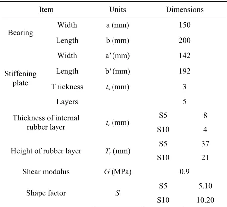
A series of elastomeric bearings were designed and fab- ricated in compliance with KS. KS presents 6 types of elastomeric bearings. The adopted elastomeric bearings is of type B with outer steel plate of KS exhibiting a shear modulus of 0.9. It is a monolithic structure ob- tained by vulcanization of the rubber pad and external steel plates. Specimens were classified into S5 and S10. Specimen S5 has the doublefold elastomeric layer. Spe- cimen S10 adopted the single elastomeric layer. The shapes and dimensions of the fabricated elastomeric bea- rings are presented in Figures1 to 2 and in Table 1.
3. Shear Performance Test
3.1. Test Machine
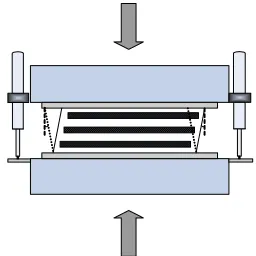
Figure 3 shows a test machine. It can apply simultane-
ously vertical and horizontal loads. The capacity of the vertical actuator of the bearing testing device is a maxi- mum load of 3500 kN and a stroke of 350 mm. The ca- pacity of the horizontal actuator is a maximum load of 500 kN and a stroke of 700 mm.
3.2. Shear Fatigue Test
52
200
3
2.
5
[image:2.595.367.475.80.359.2]8
Figure 1. Specimens S5.
36
200
3
2.
5
4
Figure 2. Specimens S10.
[image:2.595.61.285.83.396.2]Figure 3. Test machine.
Table 1. Dimensions of the elastomeric bearing specimens.
Item Units Dimensions
Width a (mm) 150
Bearing
Length b (mm) 200
Width a' (mm) 142
Length b' (mm) 192
Thickness ts (mm) 3
Stiffening plate
Layers 5
S5 8 Thickness of internal
rubber layer tr (mm)
S10 4 S5 37 Height of rubber layer Tr (mm)
S10 21
Shear modulus G (MPa) 0.9
S5 5.10
Shape factor S
S10 10.20
shear fatigue of the bearing. The total shear strain con-sider the shear strain caused by compressive load, rota-tion and shear force (Figure 4). KS prescribes the total
strain to be smaller than 500% of the total height of the rubber of the bearing (Equation (1)).
5.0
t c s
(1) Shear fatigue tests were carried out on 3 specimens in
Shear Strain
(a)
Shear Strain
(b)
Shear Strain
(c)
Figure 4. Total shear strain of elastomeric bearing (γt). (a) Shear strain due to compression (γc); (b) Shear strain due to rotation (γα); (c) Shear strain due to shear force (γs).
order to examine the fatigue stability of the elastomeric bearing with regard to this total shear strain proposed by KS. The shear fatigue test is a test applying repeatedly shear deformation while maintaining constant vertical stress in the bearing (Figure 5).
Assuming that the bridge has a service life of 50 years, the deformation of the superstructure caused by tem- perature will experience a total of 18,250 horizontal dis- placement cycles on a daily average. The shear deforma- tion had thus to be applied at frequency of 0.000116 Hz in order to reflect it in the shear fatigue test but it was impracticable. Accordingly, the loading speed of the shear deformation was determined as 0.2 Hz with refe- rence to the example of previous researchers [2,3], and the number of cycles was set to 20,000 cycles instead of the required 18,250 cycles for the execution of the shear fatigue tests.
Table 2 summarizes the shear fatigue test program. In
[image:2.595.58.287.421.630.2][image:3.595.107.235.84.212.2]
Figure 5. Conceptual scheme of shear fatigue test.
Table 2. Shear fatigue test program.
Shear Strain Specimen
Compressive Stress
[MPa] γc γs γα γt
Vertical load [kN]
Horizontal displacement
[mm]
S5#4 12 3.92 0.9 0 4.82 270 33.3
S5#5 12 3.92 0.7 0 4.62 283 25.9
S10#6 40 6.53 0.9 0 7.41 983 18.9
3.3. Ultimate Shear Test
Ultimate shear tests were carried out on 2 specimens in order to examine the shear behavior of the elastomeric bearing at ultimate state. S5#3 is the specimen of single elastomeric layer and S10#5 is of doublefold elastomeric layer. Ultimate shear test provoked shear deformation until failure of the bearings while maintaining a constant vertical stress. In order to prevent the possible occurrence of uplift force in the elastomeric bearings, the shear de- formation was provoked under application of a load cor- responding to the minimum compressive stress of 3 MPa of KS (Table 3). The shear deformation was applied at
speed of 0.2 mm/sec. The horizontal load and horizontal displacement of the bearing were measured. The external appearance was also observed during the ultimate shear test to verify the eventual occurrence of anomalies in the bearing according to the increase of the shear strain. Ul- timate shear tests were also conducted for specimens which didn’t failed from shear fatigue tests.
4. Test Results
4.1. Shear Fatigue Test
This study carried out shear fatigue tests to verify the ultimate shear performances of the Korean elastomeric bearings. Various total shear strains were adopted.
The results of the shear fatigue test are summarized in
Table 4. The change of the external appearance of the
elastomeric bearings according to the number of shear cycles was observed. Specimen S10#6 adopting single elastomeric layer was set to the highest total strain of 7.41. S10#6 showed no particular damage or dilatation
Table 3. Ultimate shear test program.
Specimen Compressive stress [MPa] Shear deformation
S5 #3 3 Until failure
S10 #5 3 Until failure
sufficient to provoke their loss of performance after 20,000 cycles.
On the other hand, externally visible damage or failure occurred for all the tested specimens S5, of doublefold elastomeric layer, despite this series of specimens was set to secure a total shear strain below the maximum value of 5.0 of the KS. Observing the specimens for which problems occurred during the shear fatigue tests, early failure occurred for specimen S5#4 at about 700 cycles (Figure 6). Shear failure of elastomeric bearings gener-
ally occurs through debonding that is the separation of the stiffening plates from rubber layers. However, specimen S5#4 failed by separation following the forma- tion of an interface inside each of the rubber layers. Fig- ure 7 shows the changes of external appearance accord-
ing to shear cycles. Specimen S5#5 experienced severe external damage during the shear fatigue test even if the specimen did not fail completely since the applied shear strain due to horizontal movement was smaller than that of specimen S5#4. The local dilatation of rubber started to appear clearly since 12,000 cycles, worsened with increasing cycles to experience outflow of the internal rubber at 17,000 cycles following the aggravated loss of the vulcanization of the elastic pad and external stiffen- ing plate.
4.2. Ultimate Shear Test
This study performed the ultimate shear tests in order to examine the shear behavior of the elastomeric bearings at ultimate state. Figure 8 shows the failure of elastomeric
[image:3.595.309.538.102.153.2]bearings under ultimate shear test. The specimen S10#5 failed through the tearing of rubber. However, S5#3 adopting doublefold elastomeric layer exhibited some difference from the common shear failure pattern by tearing of the rubber along the measurement interface in the internal rubber layer.
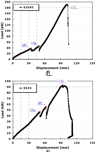
Figure 9 shows the load-displacement curves of elas-
[image:3.595.57.287.258.335.2]Table 4. Summary of shear fatigue test results.
Specimen elastomeric layer Doublefold Eventual visible damage or failure
S5 #4 ○ Failure after 700 cycles
S5 #5 ○ Severe visible damage
[image:4.595.58.286.102.468.2]S10 #6 x No anomaly
Figure 6. S5#4 after 700 cycles.
(a) (b)
(c) (d)
Figure 7. Change of external appearance according to shear cycles for specimen S5#5. (a) After 10,000 cycles; (b) After 12,000 cycles; (c) After 17,000 cycles; (d) After 20,000 cycles.
(a)
[image:4.595.340.506.440.704.2](b)
Figure 8. Shear failure. (a) S10#5; (b) S5#3.
doublefold elastomeric layer failed at shear strain of 253 percent. Elastomeric bearings of doublefold elastomeric layer exhibit low shear performance.
In the Figure 9 temporary loss of the load could be
observed twice before the failure. This can be explained by the occurrence of temporary separation at the surface of contact between the elastic pad and external steel plate as observed during the visual inspection executed during the test. The elastomeric bearings used for the ultimate shear test are bearings fabricated with a monolithic struc- ture combining the elastic pad and external steel plates by vulcanization, which means that the specimens should behave monolithically until the ultimate shear strain. However, these two specimens did not behave mono- lithically even under very low strain before the failure and experienced temporary separation at the surfaces of contact between the elastic pad and external steel plates. At the time when separation occurred at one of the two surfaces of contact, the shear strain of the elastomeric bearing happened to recover to some extent. Thereafter, it seemed that the specimens sustained the shear defor- mation until failure owing to the frictional force caused by the applied vertical load and the chemical residual friction force caused by the vulcanization.
In shear fatigue test, two of three specimens didn’t show fatigue failure. In this study, additional ultimate shear test were carried out on these specimens. Figure 10
shows the load-displacement curves of specimens which
0 20 40 60 80 100 120 140 160 180 200
0 30 60 90 120 150
Displacement [mm]
Loa
d
[k
N
]
S10#5
165%237%
493%
(a)
0 10 20 30 40 50 60 70 80 90 100
0 30 60 90 120 1
Displacement [mm]
Lo
ad
[
k
N
]
50 S5#3
137% 169%
253%
(b)
[image:4.595.111.233.511.717.2]0 20 40 60 80 100 120 140 160 180 200
0 20 40 60 80 100
Displacement [mm]
Lo
a
d
[k
N
]
S10#6
172% 228%
411%
(a)
0 10 20 30 40 50 60 70 80 90 100
0 10 20 30 40 50 60 70 80 90 100 Displacement [mm]
Loa
d
[k
N
]
S5#5
174% 219%
230%
(b)
Figure 10. Shear force-displacement curve. (a) S10#6; (b) S5#5.
didn’t failed at the shear fatigue tests. The reduction of ultimate shear performance was also observed for the bearing of doublefold elastomeric layer. And temporary loss of the load before the failure also observed.
The temporary separation of the bearing observed dur- ing the ultimate shear tests occurred within 200% of the shear strain for some specimens. Considering the allow- able shear strain of KS, such temporary separation may not be problematic when the bearing is under service. However, it is recommended that the elastomeric bear- ings fabricated in compliance with KS should sustain slightly higher level of shear deformation since they may be used for the seismic design complementarily to other seismic devices despite such bearings are not seismic isolators. In addition, even if not specified in KS, the Korean Highway Bridge Design Code [5] requires the shear strain of laminated rubber type seismic isolator to be 200% during earthquake and the Japanese Manual for Highway Bridge Bearings requires the shear strain to be up to 150% (level 1) and 250% (level 2) in the case of a seismic event. This means that when the ordinary elas- tomeric bearing is applied for the seismic design, unex- pected impact or stress concentration may occur in the bridge system due to the separation of the bearing.
5. Conclusion
For elastomeric bearings to behave monolithically, the nternal rubber which is located between the steel plates
should be the single rubber layer. In Korea, elastomeric bearings of doublefold elastomeric layer are common practice, because the current KS doesn’t restrict the use of doublefold elastomeric layer.
In this paper ultimate shear tests and shear fatigue tests were conducted on elastomeric bearings designed in compliance with KS. Some specimens are of single elas- tomeric layer, the other are of doublefold elastomeric layer.
The results of the shear fatigue tests and ultimate shear tests show that the elastomeric bearing whose internal rubber layer is formed by agglomeration of several rub- ber pads is likely to experience significant loss of its shear performances or early failure.
The elastomeric bearings adopted in this study satisfy the allowable shear strain of KS. However, separation of the surface of contact between the elastic pad and exter- nal steel plate occurred for some elastomeric bearings at shear strain of about 200%. Considering that the elas- tomeric bearing may be used in the seismic design, such separation may provoke unexpected impacts or concen- tration of stress in the bridge system. Accordingly, rele- vant specifications should be established to prevent the fabrication of such bearing. Furthermore, assuming that the elastomeric bearing behaves monolithically without occurrence of separation at the surface of contact be- tween the elastic pad and external steel plate, the elas- tomeric bearing produced in Korea was verified to secure satisfactory shear performances.
6. Acknowledgements
This research was supported by a grant from a Strategic Research Project (Development of design and construc- tion system technology for hybrid cable stayed bridge) funded by the Korea Institute of Construction Technol- ogy.
REFERENCES
[1] Korea Standards Association, “KS F 4420 Steel-Lami- nated Elastomeric Bearings for Bridge,” Korea Agency for Technology and Standards, Ministry of Knowledge Economy, Gwacheon, 1998.
[2] J. V. Muscarella and J. A. Yura, “An Experimental Study of Elastomeric Bridge Bearings with Design Recommen- dations,” Ph.D. Thesis, University of Texas, Austin, 1995. [3] C. Roeder, et al., “Performance of Elastomeric Bearings,”
Transportation Research Board, NCHRP Report 298, 1987.
[4] Japan Road Association, “Bearing Support Design Guide,” Sciencebook, Seoul, 2004.
[5] Korea Road & Transportation Association, “Korean High- way Bridge Design Code,” Ministry of Construction Trans- portation, Seoul, 2005.