IEEE Proof
Multidomain Optimization of High-Power-Density
PM Electrical Machines for System
Architecture Selection
12
3
Dmitry Golovanov, Luca Papini, David Gerada, Zeyuan Xu, and Chris Gerada, Member, IEEE
4
Abstract—The power density of electrical machines for 5
transport applications has become a critical aspect and tar-6
get of optimization. This paper looks at the development 7
of an intelligent, rapid, flexible, and multidomain tool to aid 8
for system-level optimization of electrical machines within 9
next-generation high power density applications. The elec-10
tromagnetic, thermal, and mechanical aspects are wholly 11
integrated, thus enabling the optimization including the 12
nonactive mass. The implementation and overall architec-13
ture of the tool are described, and using a case study drawn 14
from the aerospace industry, the tool is used to compare the 15
power density of various surface permanent magnet topolo-16
gies including single airgap and dual airgap machines, high-17
lighting the particular suitability of the dual rotor topology 18
in achieving the best power to mass ratio. Finally, the ac-19
curacy of the tool is highlighted by practical realization and 20
experimental validation. 21
Index Terms—High power density, multidomain, 22
optimization, permanent magnet machines, transportation. 23
I. INTRODUCTION
24
W
ITH the globally increasingly stringent emissionsleg-25
islations and fuel economy requirements, companies in
26
the transportation sector are actively and intensely researching
27
new technologies, which often involve electrification and hence,
28
the use of electrical machines for either motoring or generation.
29
The performance targets in this type of work are various and
de-30
pend a lot on the specific industry and application. For example,
31
“high power density” is often a key phrase to distinguish new
32
developments. In the land transportation industry, more
specifi-33
cally for road transportation, where volume is often highly
con-34
strained, the key power density metric is the power to volume
35
ratio or kW/L, with numbers such as 4.8 and 4.2 kW/L achieved
36
Manuscript received March 3, 2017; revised June 20, 2017 and September 7, 2017; accepted September 13, 2017. (Corresponding
author: Luca Papini.)
D. Golovanov, L. Papini, and D. Gerada are with the University of Nottingham, Nottingham NG7 2RD, U.K (e-mail: Dmitry.Golovanov@
nottingham.ac.uk; [email protected]; david.gerada@
nottingham.ac.uk).
Z. Xu is with the Department of Mechanical, University of Nottingham, Nottingham NG7 2RD, U.K (e-mail: [email protected]).
C. Gerada is with the School of Electrical and Electronic Engi-neering, University of Nottingham, Nottingham NG7 2RD, U.K (e-mail: [email protected]).
Color versions of one or more of the figures in this paper are available online at http://ieeexplore.ieee.org.
Digital Object Identifier 10.1109/TIE.2017.2772188
Fig. 1. State-of-the-art high power density motors in the automotive
Nissan and aerospace industries Siemens.
by Toyota and Nissan [1], respectively. Current hybrid vehicle 37
research programs are targeting in excess of 6 kW/L for the 2020 38
electrical machine challenge proposed by the U.S. Department 39
of Energy [2], [3]. On the other hand, for the aerospace industry, 40
mass minimization, rather than volume, is critical and the key 41
power density metric is the power to mass ratio or kW/kg, with 42
various numbers published to show achievements of particular 43
developments, such as a recent 5.2 kW/kg by Siemens for a 44
light electric aircraft [4]. Fig. 1shows two often cited recent 45
developments within the automotive and aerospace industries 46
which present new points of reference for the current state of 47
the art. 48
Engineers working on the system concept and integration of 49
the aforementioned more electric transport architectures often 50
face a bottleneck when it comes to the electrical machine. Whilst 51
comprehensive libraries of say, high speed bearings, or high 52
speed turbines are normally available either through supplier 53
input or in-house designs, for the high-performance electrical 54
machines targeted in such work, the available data is very lim- 55
ited. Doing machine sizing in a manual manner for the range 56
of options which the system architects want to investigate is 57
too much time consuming and impractical due to the number of 58
permutations involved, while narrowing down the options risks 59
in missing the system optima altogether. From the foregoing 60
discussion, clearly a tool is required to rapidly generate and 61
assess optimal electrical machine solutions based on defined 62
constraints taking into account the various sciences involved. 63
This paper describes the development of such a tool. In the 64
first part the methodology, behind the tool development and its 65
implementation are described. The tool is then adopted and used 66
for an aerospace application where it is required to compare the 67
achievable kW/kg for various permanent magnet (PM) machine 68
configurations under an intense cooling regime, with the intent 69
IEEE Proof
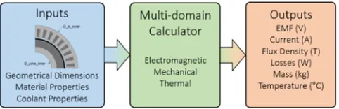
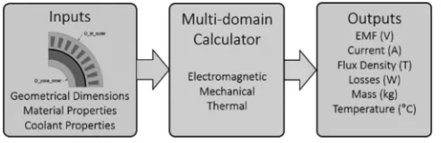
Fig. 2. Multidomain calculators required for optimization.
of establishing, which PM machine topology yields the best
70
power to mass characteristic.
71
II. REQUIREMENT ANDMETHODOLOGY
72
At the early stages of transport electrification projects, the
73
known data with which the system architects start is typically
74
quite limited in nature. This often includes fundamental items,
75
such as the power rating based on the vehicle size, a speed range
76
based on existing turbines or engine designs, together with a list
77
of available coolants. For the example in hand, the power node
78
investigated of 1 MW has to be achieved at a single speed only,
79
and a family of existing turbines within speeds from 8000 to
80
20 000 rpm are available. While the overall goal of maximizing
81
the kW/kg is known, other items such as the volume, or aspect
82
ratio of the machine are not specified and can be accommodated
83
by the system designers who are often starting from a blank
84
(flexible) design space.
85
Surface permanent magnet (SPM) machines are known to
86
be capable of achieving the highest power-densities [5] for a
87
single power-speed design point requirement. However, various
88
types of SPM machines exist (inner rotor (IR), outer rotor (OR),
89
dual-airgap, etc.) and it is not immediately obvious which of
90
the aforesaid SPM configurations gives the best kW/kg if the
91
volume is left unconstrained.
92
Finally, in determining which type of SPM machine yields the
93
best kW/kg, therefore, targeting mass minimization, it is
impor-94
tant that the inactive mass is considered within the optimization
95
procedure. By way of example, considering a previously
devel-96
oped high power density aerospace motor, the inactive mass is
97
as high as 34% of the total machine mass [6]. In many classical
98
optimization approaches, the optimization is first done on the
99
electromagnetics, then a housing is designed around the
opti-100
mized electromagnetic design. However, the housing can be a
101
very significant proportion of the total mass and integrating the
102
housing design with the overall machine kW/kg optimization
103
has high potential for extra power density entitlement.
104
Appropriate multidomain calculators, which serve as the
es-105
sential building blocks with which the kW/kg optimization is
106
performed, are required. To this end, for each SPM topology
107
considered, electromagnetic, thermal, and mechanical
analyti-108
cal models are developed, as shown inFig. 2.
109
The arbitrary SPM machines are defined in terms of their
110
characterising geometries, constituent materials defined by their
111
magnetic, mechanical and thermal properties, as well as the
112
coolant properties which include the coolant temperature and
113
flow rate. The following sections detail the multidomain
calcu-114
lators implemented and used within the optimization tool.
115
Fig. 3. Considered topologies of PM machines. (a) IR. (b) OR (c) DS. (d) DR.
III. ELECTROMAGNETICCALCULATOR 116
The analytical electromagnetic calculations are performed on 117
any arbitrary geometry defined for the topologies under investi- 118
gation. The geometrical parameters of the considered machine 119
topologies are shown inFig. 3, which include single air gap 120
machines, namely the IR and the OR topologies. Furthermore, 121
dual air gap machines are also considered namely the dual stator 122
(DS) and the dual rotor (DR) topologies. An ideal Halbach array 123
structure is selected for the rotor of the IR, OR, and DR topolo- 124
gies, allowing to achieve high fundamental air-gap flux densities 125
whilst reducing the harmonic content [7], and the amount of soft 126
magnetic material required for the rotor core. The electromag- 127
netic model for the considered topologies is for a three-phase 128
single layer distributed winding, with an additional winding 129
group for the (DS) machine. The material selected for the stator 130
structure consists of multiple ultrathin cobalt–iron laminations 131
in a thickness of 0.05 mm which represents a best-in-class ma- 132
terial in terms of saturation flux density and high frequency 133
core losses. The arbitrary machine geometry is initially used to 134
compute the no-load magnetic field according to the analytical 135
model of machines with a Halbach array [8]. Under linear be- 136
haviour of magnetic materials, the solution for the fundamental 137
of the radial component of flux density in the air gap for the IR 138
and OR topologies is given in [7]. The flux density estimation 139
for the DS topology had been described in [9]. 140
The flux density in the air gaps of the DR machine is evaluated 141
by the introduction of auxiliary virtual PMs [10] that represent 142
the influence of ferromagnetic teeth on the magnetic field. The 143
phase rms value back EMF for the IR, OR, DS, and DR designs 144
is then calculated by the following equation: 145
Eph =π
√
2feWphΦ0Kw (1)
whereWphis the number of turns per phase,feis the electrical 146
fundamental frequency, Kw is the winding factor, and Φ0 is 147
IEEE Proof
Fig. 4. Vector diagram of considered synchronous machines.
following equation:
149
Φ0 =πpL RstBr. (2)
In the above equation,Bris the average value of the
fun-150
damental radial flux density component in the air gap, p is the
151
number of rotor pole pairs, L is the active axial length, andRst
152
the radius of the stator surface.
153
The machine is analyzed in generation mode. The d–q axis
154
model is adopted with the rotor considered aligned to the
q-155
axis. Imposing the d-axis current to zero, the resulting phasor
156
diagram is shown inFig. 4. The phase currentIph can then be
157
estimated from the following equation:
158
Iph = Pel
m·Eph·η
(3)
where Pel is the electromagnetic power, m is the number of
159
phases, andη is the efficiency. The number of turns is limited
160
by the fixed dc-link voltage which is set to 2 kV while the
wind-161
ing resistance is calculated considering a slot fill factor of 0.5.
162
The reactance is calculated by means of analytical expressions
163
[11], and the power factor is thus derived accordingly. For the
164
loss calculation, the dc copper losses and the iron losses are
165
considered.
166
The flux densities for the iron loss calculation are evaluated
167
by means of a linear magnetic circuit calculation and considered
168
as average values on the overall structure. The armature current
169
flux density is evaluated using the approach described in [12].
170
Given the specific loss of a lamination material say at a
fre-171
quency of 60 Hz and at an induction of 1 T—WFe 60,1, for any
172
stator fundamental frequency—fs, and iron flux-density level
173
Bs, the specific iron losses can be approximated from [13] the
174
following equation:
175
WFe =WFe 60,1 2 Bs
1.6fs 60+
WFe 60,1 2 Bs
2
fs
60 2
(4)
whereBs is the on-load flux density [9].
176
IV. MECHANICALCALCULATOR
177
For the mechanical calculator, the input is the same arbitrary
178
active electrical machine geometry ofFig. 3, together with the
179
mechanical properties of the constituent materials. Based on
180
these inputs, the mechanical calculator estimates the mass of the
181
active materials (i.e., mass of copper, magnets, and iron) and also
182
sizes an appropriate housing around the active geometry with
183
the intent of calculating the nonactive mass.Fig. 5details the
184
housing sized around the IR SPM configuration showing the
185
Fig. 5. General housing design and cooling configurations for IR topology.
Fig. 6. Bearing mass data and interpolating functions.
TABLE I
INNERROTORMACHINEINACTIVEPARTS ANDMATERIALS
Item# Descriptions Material Density (kg/m3) Form
Stator Housing
1 Housing shells AL6061 2700 Cylindrical shell (inner+outer)
2 Two end flanges AL6061 2700 Hollow disk 3 Cooling channels AL6061 2700 Rectangular
Rotor Assembly
4 Rotor shaft 17-4PH 7780 Cylindrical shaft 5 Rotor balance plates SS316 7990 Hollow disk 6 Magnet retention sleeve Carbon Fiber 1600 Cylindrical ring
Bearings
7 Drive end bearings ✗ ✗
8 Non drive end bearings ✗ ✗
axial cross section (left) and radial cross section (right) with the 186
colour grey denoting the stator housing, colour green denoting 187
the rotor shaft, colour yellow for the stator laminations, colour 188
brown for the copper, and colour red/blue for the permanent 189
magnets. 190
Continuing with the case of the IR topology, there are a to- 191
tal of eight inactive parts which are sized for a mechanical 192
factor of safety of at least 1.5 and assuming the machine to 193
be foot mounted. The aforesaid eight inactive parts are num- 194
bered inFig. 5and listed inTable I. The stator housing (grey) 195
is made up of items#1–#3 which correspond to two cylindri- 196
cal shells (item#1), enclosing end-flanges (item#2), and cooling 197
channels. All the aforesaid components are made of lightweight 198
aluminium having a density of 2700 kg/m3in order to minimize 199
the mass. 200
The rotor assembly supporting the Halbach magnet array is 201
IEEE Proof
ing to a rotor shaft made of high strength, magnetically
perme-203
able 17-4ph stainless steel which has a hollow cross section
204
to minimize the mass (item#4), two rotor balance plates made
205
of stainless steel (item#5), and a lightweight carbon-fiber sleeve
206
(item#6) which retains the magnet under compression. Prestress
207
is applied within the carbon-fiber sleeve to ensure that a
posi-208
tive pressure is kept on the magnets throughout the operational
209
speed range as described by the following equation:
210
Ptotal=Pprestress−Pm ag sp eed−Psleeve sp eed >0 (5)
where Pprestress is the prestress pressure, while Pm ag sp eed
211
Psleeve sp eed are the pressure of the magnet and the sleeve,
re-212
spectively, due to centrifugal affects. The calculation of these
213
depend on the speed, material density as well as the radii of the
214
sleeve and magnet [22]
215
While ensuring that the condition described by (5) is satisfied,
216
the maximum pressure applied on the sleeve should not result
217
in the stress within the sleeve reaching values beyond the yield
218
strength of the sleeve material as described by the following
219
equation:
220
σtotal=σprestress+σsleeve sp eed< σm aterial (6)
where σprestress is the stress due to the preload pressure,
221
σsleeve sp eedis the sleeve stress at the overspeed condition, and
222
σm aterialis the material yield strength.
223
Apart from maintaining the stress of the various components
224
within a safe limit, in sizing the inactive parts it is also important
225
to ensure that there is sufficient torque transmission capability.
226
To this end a minimum shaft diameterDm inis calculated based
227
on the torque transmission requirement as described by the
fol-228
lowing equation:
229
Dm in =
2·J·τ
T (7)
where T is the shaft torque, and J is the hollow shaft’s polar
230
moment of inertia.
231
With the minimum shaft diameter determined, the bearing
232
inner diameter can, therefore, be selected. For the drive-end, a
233
cylindrical bearing is selected (item#7), while for the
nondrive-234
end a pair of back-to-back angular-contact bearings are used
235
(item#8), as shown inFig. 5. In determining the bearing mass,
236
linear correlations between bearing inner diameter and mass of
237
the bearing are derived based on the available bearing data [14],
238
as shown inFig. 6.
239
The procedure for calculating the inactive mass around
ar-240
bitrary geometries of the OR, DS, and DR topologies follows
241
a similar methodology to that described for the IR and hence,
242
does not necessitate a detailed description. The cross sections
243
for these machines are shown in Fig. 7 with the same color
244
coding maintained as with the IR machine.
245
For the OR topology, as shown inFig. 7(a), the rotor
assem-246
bly is made-up of a lightweight structure in titanium, with the
247
magnets attached at the inside of the aforesaid structure.
Tita-248
nium is used for the rotor inactive material since the large rotor
249
diameter would result in a comparatively large inactive mass if
250
stainless steel were to be used as with the IR topology. The DS
251
topology structure is conceptually similar to the OR, with an
252
Fig. 7. General housing design and cooling configurations for OR, DS, and DR topologies. (a) Outer rotor machine design. (b) Double stator machine design. (c) Double rotor machine design.
external stator and stator housing added, as shown inFig. 7(b). 253
Finally, for the DR topology, the internal rotor assembly has a 254
rigid connection by an end-disk to the external one. The stator 255
core of the machine is supported by bars through the stator lam- 256
inations which are fixed to a mounting plate at one end of the 257
machine, as shown inFig. 7(c). 258
V. THERMALCALCULATOR 259
For the thermal calculator, the inputs are the same arbitrary 260
electrical machine geometries as well as the thermal conduc- 261
tivities of the materials used. In addition to these, the thermal 262
calculation tool requires as inputs the coolant thermal properties 263
such as the density, viscosity, and conductivity, the inlet temper- 264
ature and the flow-rates. Based on the aforesaid inputs, together 265
with the calculated machine losses from the electromagnetic 266
calculator, the thermal calculator estimates the temperatures at 267
various locations within the electrical machine. The cooling 268
technique strongly impacts the power density level [15] and for 269
the purpose of this paper intensive, high flow-rate direct oil- 270
cooling [6] is considered, as described in the following sections 271
since the framework of this research targets high power density. 272
In order to efficiently extract the heat out of the machine, it 273
is best to locate the heat sink as closely as possible to the heat 274
source. The minimization of the thermal resistances between the 275
heat sources and the coolant enables efficient heat removal [16]– 276
[18]. For the SPM machines under investigation, rectangular 277
cooling channels are thus created in the stator slots, back iron, 278
and teeth, as shown inFig. 5, where most of the heat generated 279
IEEE Proof
Referring toFig. 5for the case of the IR topology, oil flows
281
into the flooded stator chamber from the nondrive end of the
ma-282
chine, impinging on the end-winding surfaces through multiple
283
jet-nozzles, as shown by the black arrows. The oil at the nondrive
284
end chamber is forced to flow through the cooling channels in
285
the stator core, and within slots, shown by the white and blue
286
arrows, respectively, inFig. 5. A thin sleeve is applied in the
287
airgap to ensure that the rotor chamber is free of oil and this
288
helps avoid high windage losses since the machine is running
289
at high speed. A separate oil flow is also added to the machine
290
housing-jacket, as shown by the yellow arrows in the aforesaid
291
figure.
292
Based on the above cooling concept, a lumped parameter
293
thermal model is developed. For convective heat transfer, the
294
heat transfer coefficients inside the rectangular cooling
chan-295
nels depend on the flow patterns. The flow patterns are in turn
296
determined by the evaluation of the Reynolds numberRe,
de-297
fined as [19]
298
Re = U·Dh
v (8)
where U is the flow velocity in the cooling channel, Dh is
299
the hydraulic diameter, and v is the viscosity of coolant in the
300
cooling channel. The velocity in the cooling channels can be
301
calculated from [16]
302
U = V
H·W (9)
where H and W are the height and width of the rectangular
303
cooling channels, respectively, and V is the volume flow rate in
304
each cooling channel.
305
When the Reynolds numberReof the flow in cooling channel
306
is less than 2300, the flow is said to be laminar, whilst when
307
higher than 2300 the flow in the cooling channels is turbulent.
308
For laminar flow, the heat transfer coefficient h can be calculated
309
from [18]
310
Nu = h·Dh
kf = 3.66 +
0.065·Re·Pr·DhL
1 + 0.04(Re·Pr)2/3 (10)
while for turbulent flow [17]
311
Nu = h·Dh
kf = 0.023 Re
0.8 0Pr.3 (11)
whereNuis the Nusselt number which is defined as the ratio of
312
convective to conductive heat transfer of the cooling channel,
313
kf is thermal conductivity of the cooling fluid, andPris the
314
Prandtl number of coolant. From (10) and (11), the heat transfer
315
coefficient at the cooling channels in the slot, tooth, back iron,
316
and machine housing can be determined. For the end winding
317
cooling, the heat transfer coefficient is estimated based on
pre-318
vious experimental work by the authors and measured to be
319
around 1000 to 3000 W/m2K depending on the flow rate and oil
320
jet design [6].
321
The cooling strategy and procedure for calculating the thermal
322
performance of the OR, DS, and DR topologies follows a similar
323
methodology to that described for the IR, as shown inFig. 7,
324
with the same color-coding used for the coolant flow arrows as
325
with the IR machine.
326
VI. OPTIMIZATIONMODEL 327
The preceding sections have described the main aspects be- 328
hind the development of electromagnetic, mechanical, and ther- 329
mal calculators with defined inputs and outputs for the analysis 330
of any arbitrary SPM machine geometry. The combination of 331
the three domains in a single MATLAB script acts as a multido- 332
main evaluation calculator. This can be readily used within the 333
optimization problem [20], [21], where it is required to maxi- 334
mize the kW/kg considered as the key performance metric for 335
this study. 336
In order to determine the optimum designs for the dif- 337
ferent SPM topologies presented, a genetic algorithm which 338
is embedded in the commercial optimization software mode- 339
Frontier is used. The optimum machine design is sought in a 340
wide search space defined by the rotor speed and pole pairs 341
which are limited by the maximum fundamental electrical fre- 342
quency of 1.5 kHz permissible by the power-electronic con- 343
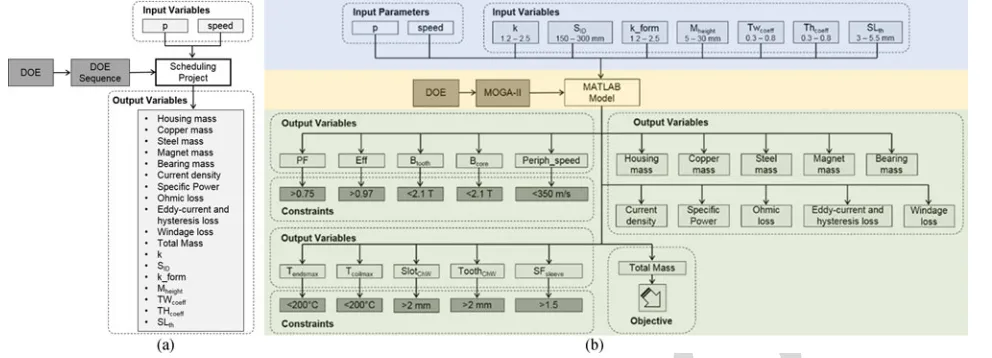
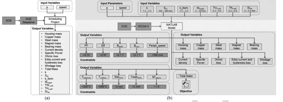
verter. The optimization model, as shown in Fig. 8, for the 344
case of the IR topology, consists of a so-called “scheduling 345
project node” and a “nested optimization procedure.” In es- 346
sential terms, the scheduling project node initializes the pole- 347
pairs and speed variables for the nested optimization procedure. 348
For each combination of speed and pole-pair numbers defined 349
in the “scheduling project node,” the aforesaid parameters are 350
transferred as input parameters to the “nested optimization pro- 351
cedure.” Continuing with the example of the IR topology, the 352
machine geometry is characterized by seven defining variables, 353
grouped under the heading “Input Variables,” shaded in blue 354
in Fig. 7 and related with the geometry presented in Fig. 3. 355
These variables are the split ratio “k” stator inner diameter 356
“SID” aspect ratio “k_form” magnet height “Mheight,” tooth 357
width coefficient “TWco eff” tooth height coefficient “THco eff,” 358
and carbon fiber sleeve thickness “SLth.” These parameters 359
are easily understandable by the electrical machine designer 360
and allow us to parameterize the main geometry of the ma- 361
chine. The defining input variables and their relation to the 362
machine geometries for each topology shown inFig. 3are listed 363
inTable II. 364
With the range and number of discrete values set for the input 365
variables, the next step is to define the Design of Experiment 366
(DoE), the optimization algorithm, and the multidomain cal- 367
culation scripts, as shown and shaded in brown in Fig. 8. For 368
the DoE, based on the upper and lower limits together with the 369
number of discrete values for the seven input variables, an initial 370
population of machine designs is generated using a pseudoran- 371
dom sequence. 372
The initial population is typically set to around 300. The 373
optimization algorithm is selected to achieve fast computation 374
and solution robustness. The final part in the solver options 375
core is the MATLAB interface block enabling information ex- 376
change between the algorithm and the multidomain calculators 377
presented in the previous sections. 378
This interface enables the optimization to access the 379
electromagnetic-thermal-mechanical model and return the re- 380
sults to the optimization algorithm. This brings the setting-up of 381
IEEE Proof
Fig. 8. modeFrontier optimization model for 1 MW IR aerospace machine. (a) Scheduling project node. (b) Nested optimization procedure.
TABLE II
EXPRESSIONS FORINPUTVARIABLES
Input variable IR OR DS DR
k SO D
SI D
RO D−2 (Mh e i g h t+A G+R St h)
SI D SO D e x t/SID e x t[OS]SO D int/SID int[IS] ✗
SID SID ✗ ✗ ✗
kform La/SID La/RO D La/SID e x t La/RO D e x t
Mh e ig ht Mh e ig ht ✗ ✗ ✗
TWc o e ff 6πpTw i d t hSI D 6πpR Tw i d t h
O D−2 (Mh e i g h t+A G+R St h)
6p
π Tw i d t h e x tSI D e x t [OS]
6p
π RO D e x t−2 (Mh e i g h t e x tTw i d t h+A Ge x t+R St h e x t)
6p
π Tw i d t h i n tSO D i n t [IS]
THc o e ff
2Th e i g h t SO D−SI D
2Th e i g h t
RO D−2 (Mh e i g h t+A G+R St h)−SI D
2 (Th e i g h t e x t−T Sh e i g h t e x t)
SO D e x t−SI D e x t [IS] ✗
2 (Th e i g h t i n t−T Sh e i g h t i n t) SO D i n t−SI D i n t [OS]
SLt h SLt h ✗ ✗ ✗
RO D e x t ✗ ✗ ✗ RO D e x t
Delta PM int ✗ ✗ ✗ Mh e i g h t i n t RI D i n t/2 +Mh e i g h t i n t
Delta PM ext ✗ ✗ ✗ Mh e i g h t e x t RO D e x t/2−R St h e x t
Deltast ✗ ✗ ✗ Sh e i g h t
RO D e x t/2−Mh e i g h t i n t−R St h e x t−A Ge x t
SID e x t ✗ ✗ SID e x t ✗
overlap ratio ✗ ✗ 2pα/π ✗
in green in Fig. 8, in which the output variables and
opti-383
mization targets are defined. The problem in hand is single-384
objective in nature, targeting the minimization of the machine
385
total mass (active plus nonactive parts). In achieving this
tar-386
get, a number of constraints are defined on the outputs. The
387
first two constraints “Tendsm ax” and “Tcoilm ax” relate to the
388
thermal limitations, and ensure that for any design to be
con-389
sidered feasible the temperature in the winding must not exceed
390
a defined limit, which for the case in hand is set as 200 °C
391
corresponding to class C insulation. Also related to the
ther-392
mal domain, minimum practical cooling channel areas are
de-393
fined by the parameters “SlotC hW” and “ToothC hW.” For a
de-394
sign to be considered feasible the power factor “PF” and the
395
efficiency “eff” must also be higher than defined thresholds 396
(in this case power factor over 0.75 and efficiency over 97%) 397
while the on-load tooth and core flux densities are limited to 398
up to 2.1 T according to the BH characteristics of the chosen 399
material. The final output variable constraints relate to the me- 400
chanical domain and impose a peripheral speed “Periph_speed” 401
of up to 350 m/s and a rotor factor of safety “SFsleeve” 402
above 1.5. 403
The optimization has been performed on a PC with Quad Intel 404
Xeon 3.5 GHz CPU, 32 GB of installed RAM and takes around 405
2 to 2.5 h for the optimization and generation of one design. 406
To generate a topology chart consisting of 25 design points, as 407
IEEE Proof
Fig. 9. Power density against pole pair of the machine topologies.
VII. SPECIFICPOWERCHARACTERISTICS OF1 MW PM 409
MACHINES FORAEROSPACEAPPLICATIONS
410
Using the methodology described in the previous section,
411
the four radial SPM machines are optimized for a range of
412
speeds from 8 to 20 krpm considering different pole numbers
413
corresponding to an upper frequency limit of 1.5 kHz. The
414
machine power was taken equal to 1 MW. The coolant flow
415
rate is 150 L/min with an inlet temperature of 50°C. Fig. 9
416
shows the results of the optimization with the power-density
417
(kW/kg) plotted against the number of pole pairs for different
418
rotor speeds.
419
For a fixed output power, the trend is for the power density
420
to increase with the speed due to multiple factors. The lower
421
torque requirement for increasing speeds leads to a reduced
422
airgap radius and thus a smaller machine size. From the same
423
figure, it is noted that for each speed clearly there is a pole pair
424
number that yields the best power-density. As the pole number
425
(and hence machine frequency increase), the iron mass for a
426
given working flux density reduces, as does the copper loss due
427
to the reduced length of turn, however, the specific iron losses
428
increase due to the higher eddy-currents. The optimum balance
429
between the copper and iron losses is sought by the optimization
430
algorithm and the result depends on the electrical frequency,
431
electrical steel thickness, and the thermal management.
432
In order to understand the power density and comparative
433
PM topology trends ofFig. 9, it is important to put things in
434
perspective. Focusing deeper on the results of the optimization,
435
the total mass of each design and its segregation into various
436
active and inactive components is presented inFig. 10. On the
437
same figure, the ratio of the active with respect to the total mass
438
kA/T is plotted on the secondary y-axis. The total mass as well
439
as the active-to-total mass ratio reduce with the increase in the
440
rotor speed. This is mainly caused by the reduction in size due
441
to the lower torque. Significant differences in the distribution of
442
the active and nonactive mass for the different topologies across
443
different speeds can be observed. It can be, therefore, deduced 444
that the power-density achieved when optimizing the active ele- 445
ments only and adding the inactive parts postoptimization, differ 446
to those obtained if the nonactive parts are included within the 447
optimization algorithm, as proposed in this research. 448
Further important observations can be made when the losses 449
and the maximum machine operational temperature are consid- 450
ered. InFig. 11, the losses pertaining to the different optimized 451
SPM topologies are segregated. The efficiency limit of 97% 452
imposed by the application translates to a maximum level of ad- 453
missible losses of 30 kW represented by the dashed red line in 454
the aforesaid figure. It is observed that the iron losses increase 455
with the rotational speed and the number of pole pairs, how- 456
ever, they are always significantly lower than the copper losses. 457
The comparatively high amount of copper losses suggests that 458
the intensive cooling strategy proposed which involves direct 459
slot cooling enables the very high current densities of the or- 460
der of 25 A/mm2, which is the main source of power density 461
entitlement. 462
The maximum temperatures calculated for the different op- 463
timized SPM designs are also plotted on the secondary y-axis 464
of Fig. 11. The temperature limit of 200 °C imposed by the 465
class C insulation is represented by the dashed black line on the 466
same figure. It can be noticed that the machines are thermally 467
limited for lower pole numbers due to the lower number of 468
cooling channels within the stator structure, therefore, resulting 469
in a reduced surface for heat transfer. The windage losses are 470
negligible in comparison to the other machine losses. 471
The optimization results can be analyzed and discussed fur- 472
ther considering the data presented inFig. 12. In this figure, five 473
differently shaped markers (,•,,♦,) represent the lim- 474
its that the optimization algorithm hits in achieving the highest 475
power-density design for the four investigated SPM topologies. 476
In most cases, the optimization algorithm results in saturated 477
designs with high working flux-densities which represent the 478
IEEE Proof
Fig. 10. Mass segregation andkA / T factor against pole pair of the machine topologies investigated.
[image:8.594.83.526.410.724.2]IEEE Proof
Fig. 12. Limits of the optimized designs for different machine topologies.
limit. Having high working flux-densities in the iron helps in
480
reducing the size and consequently the weight of the machines,
481
however, this also reduces the surfaces for heat extraction. The
482
power factor limit (•), which is set to a minimum value of
483
0.75, results in being a limiting factor mainly for the DR and IR
484
topologies. Since all designs have a fixed air-gap length, the slot
485
geometry impacts the leakage inductance and thus the power
486
factor plays a role in combination with the flux density
satura-487
tion limit. Interestingly, the efficiency ()and the temperature
488
limits(♦)are distributed in a mutually exclusive way: the
de-489
signs which are efficiency limited are not in general thermally
490
limited and vice-versa.
491
For lower speeds, the designs are mainly efficiency limited,
492
while for higher speeds, the designs are primarily thermally
493
limited, as with the reduced volume at high speeds, besides the
494
increase of the power density, the cooling system needs to cater
495
for the increased loss-density, and hence thermal management
496
becomes critical.
497
Finally fromFig. 12, the mechanical peripheral speed limits
498
()are not normally a constraining factor within the
optimiza-499
tion except for few cases.
500
The proposed multidomain optimization tool and
methodol-501
ogy enables the investigation of a variety of design combinations
502
and its flexibility is demonstrated by the comparison of different
503
SPM machine topologies in achieving state-of-the-art power
504
densities.
505
The comparison of the power-density variation with the pole
506
number for the four SPM topologies at 20 krpm is shown in
[image:9.594.369.483.432.512.2]507
Fig. 13, highlighting the particular suitability of DR topology
508
in achieving the highest power to mass ratio with the defined
509
cooling strategy, materials as well as under no volumetric
con-510
straints.The DR topology makes advantage of the double air-gap
511
structure, has no stator back-iron and includes two Halbach
ar-512
rays that significantly increase the flux density in the active part
513
of the machine. From the same figure, the DR is followed by
514
the IR, OR, and DS configurations in terms of achieving high
515
power densities.
516
VIII. TOOLVALIDATION
517
The described optimization procedure is implemented on an
518
IR machine requirement specification. Due to size limitations
519
Fig. 13. Comparison machine topology for 20 krpm.
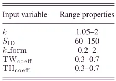
TABLE III
EXPRESSIONS FORINPUTVARIABLES
Input variable Range properties
k 1.05–2
SID 60–150
kform 0.2–2
TWc o e ff 0.3–0.7
THc o e ff 0.3–0.7
and other practical considerations, the machine to be optimized 520
and designed is scaled to a lower power level of 160 kW and 521
higher speed of 32 000 rpm. The machine is still intensively 522
cooled with an oil-flooded stator chamber as that described in 523
Section V, the oil inlet temperature being 120 °C, albeit the 524
flow rate reduced to 15 l/min due to the available system pump 525
rating.Table IIIlists the variables optimized together with the 526
respective ranges. 527
The maximum fundamental frequency which the converter 528
can be operated to is 2 kHz, which corresponds to a maximum 529
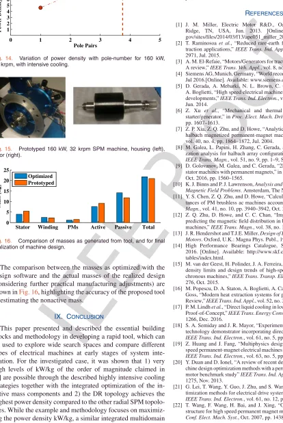
pole number of 6. Fig. 14 shows the variation of the power- 530
density with pole number, with the dashed red-line representing 531
the maximum converter operational frequency. Taking this fre- 532
quency limitation into account a 6-pole configuration with a 533
corresponding power density of 7.5 kW/kg is selected for proto- 534
typing for the application in hand.Fig. 15shows the prototyped 535
machine including the lightweight aluminium housing (blue) 536
IEEE Proof
[image:10.594.52.466.124.742.2]Fig. 14. Variation of power density with pole-number for 160 kW, 32 krpm, with intensive cooling.
Fig. 15. Prototyped 160 kW, 32 krpm SPM machine, housing (left), rotor (right).
Fig. 16. Comparison of masses as generated from tool, and for final realization of machine design.
The comparison between the masses as optimized with the
538
design software and the actual masses of the realized design
539
(considering further practical manufacturing adjustments) are
540
shown inFig. 16, highlighting the accuracy of the proposed tool
541
in estimating the nonactive mass.
542
IX. CONCLUSION
543
This paper presented and described the essential building
544
blocks and methodology in developing a rapid tool, which can
545
be used to explore wide search spaces and compare different
546
types of electrical machines at early stages of system
inte-547
gration. For the investigated case, it was shown that 1) very
548
high levels of kW/kg of the order of magnitude claimed in
549
[4] are possible through the described highly intensive cooling
550
strategies together with the integrated optimization of the
in-551
active mass components and 2) the DR topology achieves the
552
highest power density compared to the other radial SPM
topolo-553
gies. While the example and methodology focuses on
maximiz-554
ing the power density kW/kg, a similar integrated multidomain
555
approach can be also readily applied to optimize for other goals 556
typically sought in various industries such as kW/L and $/kg, 557
enabling the system architects to investigate multiple solutions 558
involving electrical machines effectively and take the appropri- 559
ate system-level decisions. 560
REFERENCES 561
[1] J. M. Miller, Electric Motor R&D., Oak Ridge Nat. Lab., Oak 562
Ridge, TN, USA, Jun. 2013. [Online].Available: https://energy. 563
gov/sites/files/2014/03/f13/ape051_miller_2013_o.pdf 564
[2] T. Raminosoa et al., “Reduced rare-earth flux-switching machines for 565
traction applications,” IEEE Trans. Ind. Appl., vol. 51, no. 4, pp. 2959– 566
2971, Jul. 2015. 567
[3] A. M. El-Refaie, “Motors/Generators for traction/propulsion applications: 568
A review,” IEEE Trans. Veh. Appl., vol. 8, no. 1, pp. 90–99, Jan. 2013. 569
[4] Siemens AG, Munich, Germany, “World record electric motor for aircraft,” 570
Jul 2016.[Online]. Available: www.siemens.com/press/electric-aircraft 571
[5] D. Gerada, A. Mebarki, N. L. Brown, C. Gerada, A. Cavagnino, and 572
A. Boglietti, “High speed electrical machines—Technologies, trends and 573
developments,” IEEE Trans. Ind. Electron., vol. 61, no. 6, pp. 2946–2959, 574
Jun. 2014. 575
[6] Z. Xu et al., “Mechanical and thermal design of an aeroengine 576
starter/generator,” in Proc. Elect. Mach. Drives Conf., May 2015, vol. 1, 577
pp. 1607–1613. 578
[7] Z. P. Xia, Z. Q. Zhu, and D. Howe, “Analytical magnetic field analysis of 579
halbach magnetized permanent-magnet machines,” IEEE Trans. Magn., 580
vol. 40, no. 4, pp. 1864–1872, Jul. 2004. 581
[8] M. Galea, L. Papini, H. Zhang, C. Gerada, and T. Hamiti, “Demagneti- 582
zation analysis for halbach array configurations in electrical machines,” 583 IEEE Trans. Magn., vol. 51, no. 9, pp. 1–9, Sep. 2015. 584
[9] D. Golovanov, M. Galea, and C. Gerada, “2D analytical model for dual- 585
stator machines with permanent magnets,” in Proc. IEEE Ind. Elect. Conf., 586
Oct. 2016, pp. 1560–1565. 587
[10] K. J. Binns and P. J. Lawrenson, Analysis and Computation of Electric and 588 Magnetic Field Problems. Amsterdam, The Netherlands: Elsevier, 2013. 589
[11] Y. S. Chen, Z. Q. Zhu, and D. Howe, “Calculation of d- and q-axis induc- 590
tances of PM brushless ac machines accounting for skew,” IEEE Trans. 591 Magn., vol. 41, no. 10, pp. 3940–3942, Oct. 2005. 592
[12] Z. Q. Zhu, D. Howe, and C. C. Chan, “Improved analytical model for 593
predicting the magnetic field distribution in brushless permanent-magnet 594
machines,” IEEE Trans. Magn., vol. 38, no. 1, pp. 229–3238, Aug. 2002. 595
[13] J. R. Hendershot and T.J.E. Miller, Design of Brushless Permanent Magnet 596 Motors. Oxford, U.K.: Magna Phys. Publ., 1994. 597
[14] High Performance Bearings Catalogue, SKF, Gothenburg, Sweden, 598
2016.[Online]. Available: http://www.skf.com/group/products/product- 599
tables/index.html. 600
[15] M. van der Geest, H. Polinder, J. A. Ferreira, and M. Christmann, “Power 601
density limits and design trends of high-speed permanent magnet syn- 602
chronous machines,” IEEE Trans. Transp. Electrif., vol. 1, no. 3, pp. 266– 603
276, Oct. 2015. 604
[16] M. Popescu, D. A. Staton, A. Boglietti, A. Cavagnino, D. Hawkins, and J. 605
Goss, “Modern heat extraction systems for power traction machines—A 606
Review,” IEEE Trans. Ind. Appl., vol. 52, no. 3, pp. 2167–2175, May 2016. 607
[17] P. M. Lindh et al., “Direct liquid cooling in low-power electrical machines: 608
Proof-of-Concept,” IEEE Trans. Energy Convers., vol. 31, no. 4, pp. 1257– 609
1266, Dec. 2016. 610
[18] S. A. Semiday and J. R. Mayor, “Experimentation of an electric machine 611
technology demonstrator incorporating direct winding heat exchangers,” 612 IEEE Trans. Ind. Electron., vol. 61, no. 5, pp. 71–78, Oct. 2014. 613
[19] Z. Huang and J. Fang, “Multiphysics design and optimization of high- 614
speed permanent-magnet electrical machines for Air blower applications,” 615 IEEE Trans. Ind. Electron., vol. 63, no. 5, pp. 2766–2774, May 2016. 616
[20] Y. Duan and D. Ionel, “A review of recent developments in electrical ma- 617
chine design optimization methods with a permanent-magnet synchronous 618
motor benchmark study” IEEE Trans. Ind. Appl., vol. 49, no. 3, pp. 1269– 619
1275, Nov. 2013. 620
[21] G. Lei, T. Wang, Y. Guo, J. Zhu, and S. Wang, “System-level design op- 621
timization methods for electrical drive systems: Deterministic approach,” 622 IEEE Trans. Ind. Electron., vol. 61, no. 12, pp. 6591–6602, Dec. 2014. 623
[22] T. Wang, F. Wang, H. Bai, and J. Xing, “Optimization design of rotor 624
[image:10.594.45.292.236.328.2]IEEE Proof
Dmitry Golovanovreceived the Ph.D. degree
627
in superconducting electrical machines from
628
Moscow Aviation Institute, Moscow, Russia, in
629
2011.
630
He has an experience of working in industry
631
as a Researcher in VNIIEM Corporation JSC,
632
Russia, in the field of design of electrical
ma-633
chines and in Samsung SDI, South Korea, in
634
the field of Li-ion batteries. He is currently a
Re-635
search Fellow in the University of Nottingham,
636
Nottingham, U.K. His main research interests
637
include high power density electric machines for aerospace and
au-638
tomotive industry application, and superconducting electrical machines.
639 640
Luca Papinireceived the B.S. (Hons.) and M.S.
641
(Hons.) degrees in electrical engineering from
642
the University of Pisa, Pisa, Italy, in 2009 and
643
2011, respectively. He is currently working
to-644
ward the Ph.D. degree with the Power Electronic,
645
Motors and Drives Group, University of
Notting-646
ham, Nottingham, U.K.
647
He has been a Visiting Student at the
Uni-648
versity of Nottingham, developing analytical and
649
numerical models for electrical machines. From
650
June to November 2011, he collaborated with
651
the Department of Energy Engineering, University of Pisa, as a
Re-652
search Assistant. Since 2013, he has been a Research Assistant with
653
the University of Nottingham. His main research interests include high
654
speed, high power density electric machines, and machine control and
655
levitating system.
656 657
David Geradareceived the B.Eng. (Hons.)
de-658
gree in electrical engineering from the University
659
of Malta, Msida, Malta, in 2007, and the Ph.D.
660
degree in high-speed electrical machines from
661
the University of Nottingham, Nottingham, U.K.,
662
in 2012.
663
From 2007 to 2016, he was with the R&D
De-664
partment at Cummins Generator Technologies,
665
Stamford, U.K., first as an Electrical Machine
De-666
sign Engineer (2007–2011) and then as a Senior
667
Electrical Machine Design Engineer and
Innova-668
tion Leader (2011–2016). In 2016, he joined the University of
Notting-669
ham as a Senior Research Fellow in Electrical Machines. His research
670
interests include high-speed machines, traction machines, use of novel
671
materials, and multiphysics-based optimization of electrical machines.
672
Dr. Gerada is a Chartered Engineer in the U.K. and a member of the
673
Institution of Engineering and Technology.
674 675
Zeyuan Xureceived the Ph.D. degree in me- 676
chanical engineering from the University of 677
Manchester, Manchester, U.K., in 2002. 678
He subsequently worked as a Research Fel- 679
low at UMIST, Brunel University, and the Uni- 680
versity of Nottingham. He is currently a Senior 681
Research Fellow in thermo-mechanical design 682
of high speed electrical machines within the 683
PEMC group at the University of Nottingham, 684
Nottingham, U.K. His main research interests 685
include turbulent thermo-fluid flow, heat trans- 686
fer enhancement, and thermal management of advanced electrical ma- 687
chines and power electronics. 688
689
Chris Gerada(M’05) received the Ph.D. degree 690
in numerical modeling of electrical machines 691
from the University of Nottingham, Nottingham, 692
U.K., in 2005. 693
He subsequently worked as a Researcher 694
with the University of Nottingham on high- 695
performance electrical drives and on the de- 696
sign and modeling of electromagnetic actuators 697
for aerospace applications. Since 2006, he has 698
been the Project Manager of the GE Aviation 699
Strategic Partnership. In 2008, he was appointed 700
as a Lecturer in the electrical machines; in 2011, as an Associate Profes- 701
sor; and in 2013, as a Professor at the University of Nottingham. His main 702
research interests include the design and modeling of high-performance 703
electric drives and machines. 704
Prof. Gerada is an Associate Editor for the IEEE TRANSACTIONS ON 705
INDUSTRYAPPLICATIONSand is the past Chair of the IEEE IES Electrical 706
Machines Committee. 707
IEEE Proof
Multidomain Optimization of High-Power-Density
PM Electrical Machines for System
Architecture Selection
12
3
Dmitry Golovanov, Luca Papini, David Gerada, Zeyuan Xu, and Chris Gerada, Member, IEEE
4Abstract—The power density of electrical machines for 5
transport applications has become a critical aspect and tar-6
get of optimization. This paper looks at the development 7
of an intelligent, rapid, flexible, and multidomain tool to aid 8
for system-level optimization of electrical machines within 9
next-generation high power density applications. The elec-10
tromagnetic, thermal, and mechanical aspects are wholly 11
integrated, thus enabling the optimization including the 12
nonactive mass. The implementation and overall architec-13
ture of the tool are described, and using a case study drawn 14
from the aerospace industry, the tool is used to compare the 15
power density of various surface permanent magnet topolo-16
gies including single airgap and dual airgap machines, high-17
lighting the particular suitability of the dual rotor topology 18
in achieving the best power to mass ratio. Finally, the ac-19
curacy of the tool is highlighted by practical realization and 20
experimental validation. 21
Index Terms—High power density, multidomain, 22
optimization, permanent magnet machines, transportation. 23
I. INTRODUCTION 24
W
ITH the globally increasingly stringent emissions leg-25islations and fuel economy requirements, companies in 26
the transportation sector are actively and intensely researching 27
new technologies, which often involve electrification and hence, 28
the use of electrical machines for either motoring or generation. 29
The performance targets in this type of work are various and de-30
pend a lot on the specific industry and application. For example, 31
“high power density” is often a key phrase to distinguish new 32
developments. In the land transportation industry, more specifi-33
cally for road transportation, where volume is often highly con-34
strained, the key power density metric is the power to volume 35
ratio or kW/L, with numbers such as 4.8 and 4.2 kW/L achieved 36
Manuscript received March 3, 2017; revised June 20, 2017 and September 7, 2017; accepted September 13, 2017. (Corresponding author: Luca Papini.)
D. Golovanov, L. Papini, and D. Gerada are with the University of Nottingham, Nottingham NG7 2RD, U.K (e-mail: Dmitry.Golovanov@ nottingham.ac.uk; [email protected]; david.gerada@ nottingham.ac.uk).
Z. Xu is with the Department of Mechanical, University of Nottingham, Nottingham NG7 2RD, U.K (e-mail: [email protected]).
C. Gerada is with the School of Electrical and Electronic Engi-neering, University of Nottingham, Nottingham NG7 2RD, U.K (e-mail: [email protected]).
Color versions of one or more of the figures in this paper are available online at http://ieeexplore.ieee.org.
Digital Object Identifier 10.1109/TIE.2017.2772188
Fig. 1. State-of-the-art high power density motors in the automotive Nissan and aerospace industries Siemens.
by Toyota and Nissan [1], respectively. Current hybrid vehicle 37 research programs are targeting in excess of 6 kW/L for the 2020 38 electrical machine challenge proposed by the U.S. Department 39 of Energy [2], [3]. On the other hand, for the aerospace industry, 40 mass minimization, rather than volume, is critical and the key 41 power density metric is the power to mass ratio or kW/kg, with 42 various numbers published to show achievements of particular 43 developments, such as a recent 5.2 kW/kg by Siemens for a 44 light electric aircraft [4]. Fig. 1 shows two often cited recent 45 developments within the automotive and aerospace industries 46 which present new points of reference for the current state of 47
the art. 48
Engineers working on the system concept and integration of 49 the aforementioned more electric transport architectures often 50 face a bottleneck when it comes to the electrical machine. Whilst 51 comprehensive libraries of say, high speed bearings, or high 52 speed turbines are normally available either through supplier 53 input or in-house designs, for the high-performance electrical 54 machines targeted in such work, the available data is very lim- 55 ited. Doing machine sizing in a manual manner for the range 56 of options which the system architects want to investigate is 57 too much time consuming and impractical due to the number of 58 permutations involved, while narrowing down the options risks 59 in missing the system optima altogether. From the foregoing 60 discussion, clearly a tool is required to rapidly generate and 61 assess optimal electrical machine solutions based on defined 62 constraints taking into account the various sciences involved. 63 This paper describes the development of such a tool. In the 64 first part the methodology, behind the tool development and its 65 implementation are described. The tool is then adopted and used 66 for an aerospace application where it is required to compare the 67 achievable kW/kg for various permanent magnet (PM) machine 68 configurations under an intense cooling regime, with the intent 69
IEEE Proof
Fig. 2. Multidomain calculators required for optimization.
of establishing, which PM machine topology yields the best 70
power to mass characteristic. 71
II. REQUIREMENT ANDMETHODOLOGY 72
At the early stages of transport electrification projects, the 73
known data with which the system architects start is typically 74
quite limited in nature. This often includes fundamental items, 75
such as the power rating based on the vehicle size, a speed range 76
based on existing turbines or engine designs, together with a list 77
of available coolants. For the example in hand, the power node 78
investigated of 1 MW has to be achieved at a single speed only, 79
and a family of existing turbines within speeds from 8000 to 80
20 000 rpm are available. While the overall goal of maximizing 81
the kW/kg is known, other items such as the volume, or aspect 82
ratio of the machine are not specified and can be accommodated 83
by the system designers who are often starting from a blank 84
(flexible) design space. 85
Surface permanent magnet (SPM) machines are known to 86
be capable of achieving the highest power-densities [5] for a 87
single power-speed design point requirement. However, various 88
types of SPM machines exist (inner rotor (IR), outer rotor (OR), 89
dual-airgap, etc.) and it is not immediately obvious which of 90
the aforesaid SPM configurations gives the best kW/kg if the 91
volume is left unconstrained. 92
Finally, in determining which type of SPM machine yields the 93
best kW/kg, therefore, targeting mass minimization, it is impor-94
tant that the inactive mass is considered within the optimization 95
procedure. By way of example, considering a previously devel-96
oped high power density aerospace motor, the inactive mass is 97
as high as 34% of the total machine mass [6]. In many classical 98
optimization approaches, the optimization is first done on the 99
electromagnetics, then a housing is designed around the opti-100
mized electromagnetic design. However, the housing can be a 101
very significant proportion of the total mass and integrating the 102
housing design with the overall machine kW/kg optimization 103
has high potential for extra power density entitlement. 104
Appropriate multidomain calculators, which serve as the es-105
sential building blocks with which the kW/kg optimization is 106
performed, are required. To this end, for each SPM topology 107
considered, electromagnetic, thermal, and mechanical analyti-108
cal models are developed, as shown in Fig. 2. 109
The arbitrary SPM machines are defined in terms of their 110
characterising geometries, constituent materials defined by their 111
magnetic, mechanical and thermal properties, as well as the 112
coolant properties which include the coolant temperature and 113
flow rate. The following sections detail the multidomain calcu-114
lators implemented and used within the optimization tool. 115
Fig. 3. Considered topologies of PM machines. (a) IR. (b) OR (c) DS. (d) DR.
III. ELECTROMAGNETICCALCULATOR 116
The analytical electromagnetic calculations are performed on 117 any arbitrary geometry defined for the topologies under investi- 118 gation. The geometrical parameters of the considered machine 119 topologies are shown in Fig. 3, which include single air gap 120 machines, namely the IR and the OR topologies. Furthermore, 121 dual air gap machines are also considered namely the dual stator 122 (DS) and the dual rotor (DR) topologies. An ideal Halbach array 123 structure is selected for the rotor of the IR, OR, and DR topolo- 124 gies, allowing to achieve high fundamental air-gap flux densities 125 whilst reducing the harmonic content [7], and the amount of soft 126 magnetic material required for the rotor core. The electromag- 127 netic model for the considered topologies is for a three-phase 128 single layer distributed winding, with an additional winding 129 group for the (DS) machine. The material selected for the stator 130 structure consists of multiple ultrathin cobalt–iron laminations 131 in a thickness of 0.05 mm which represents a best-in-class ma- 132 terial in terms of saturation flux density and high frequency 133 core losses. The arbitrary machine geometry is initially used to 134 compute the no-load magnetic field according to the analytical 135 model of machines with a Halbach array [8]. Under linear be- 136 haviour of magnetic materials, the solution for the fundamental 137 of the radial component of flux density in the air gap for the IR 138 and OR topologies is given in [7]. The flux density estimation 139 for the DS topology had been described in [9]. 140 The flux density in the air gaps of the DR machine is evaluated 141 by the introduction of auxiliary virtual PMs [10] that represent 142 the influence of ferromagnetic teeth on the magnetic field. The 143 phase rms value back EMF for the IR, OR, DS, and DR designs 144 is then calculated by the following equation: 145
Eph =π
√
2feWphΦ0Kw (1)
IEEE Proof
Fig. 4. Vector diagram of considered synchronous machines.
following equation: 149
Φ0 =πpL RstBr. (2)
In the above equation,Bris the average value of the fun-150
damental radial flux density component in the air gap, p is the 151
number of rotor pole pairs, L is the active axial length, andRst
152
the radius of the stator surface. 153
The machine is analyzed in generation mode. The d–q axis 154
model is adopted with the rotor considered aligned to the q-155
axis. Imposing the d-axis current to zero, the resulting phasor 156
diagram is shown in Fig. 4. The phase currentIph can then be
157
estimated from the following equation: 158
Iph = Pel
m·Eph·η
(3)
where Pel is the electromagnetic power, m is the number of
159
phases, andη is the efficiency. The number of turns is limited 160
by the fixed dc-link voltage which is set to 2 kV while the wind-161
ing resistance is calculated considering a slot fill factor of 0.5. 162
The reactance is calculated by means of analytical expressions 163
[11], and the power factor is thus derived accordingly. For the 164
loss calculation, the dc copper losses and the iron losses are 165
considered. 166
The flux densities for the iron loss calculation are evaluated 167
by means of a linear magnetic circuit calculation and considered 168
as average values on the overall structure. The armature current 169
flux density is evaluated using the approach described in [12]. 170
Given the specific loss of a lamination material say at a fre-171
quency of 60 Hz and at an induction of 1 T—WFe 60,1, for any
172
stator fundamental frequency—fs, and iron flux-density level 173
Bs, the specific iron losses can be approximated from [13] the
174
following equation: 175
WFe =WFe 60,1 2 Bs
1.6fs 60+
WFe 60,1 2 Bs
2
fs
60
2 (4)
whereBs is the on-load flux density [9]. 176
IV. MECHANICALCALCULATOR 177
For the mechanical calculator, the input is the same arbitrary 178
active electrical machine geometry of Fig. 3, together with the 179
mechanical properties of the constituent materials. Based on 180
these inputs, the mechanical calculator estimates the mass of the 181
active materials (i.e., mass of copper, magnets, and iron) and also 182
sizes an appropriate housing around the active geometry with 183
the intent of calculating the nonactive mass. Fig. 5 details the 184
housing sized around the IR SPM configuration showing the 185
Fig. 5. General housing design and cooling configurations for IR topology.
Fig. 6. Bearing mass data and interpolating functions.
TABLE I
INNERROTORMACHINEINACTIVEPARTS ANDMATERIALS
Item# Descriptions Material Density (kg/m3) Form
Stator Housing
1 Housing shells AL6061 2700 Cylindrical shell
(inner+outer)
2 Two end flanges AL6061 2700 Hollow disk
3 Cooling channels AL6061 2700 Rectangular
Rotor Assembly
4 Rotor shaft 17-4PH 7780 Cylindrical shaft
5 Rotor balance plates SS316 7990 Hollow disk
6 Magnet retention sleeve Carbon Fiber 1600 Cylindrical ring
Bearings
7 Drive end bearings ✗ ✗
8 Non drive end bearings ✗ ✗
axial cross section (left) and radial cross section (right) with the 186 colour grey denoting the stator housing, colour green denoting 187 the rotor shaft, colour yellow for the stator laminations, colour 188 brown for the copper, and colour red/blue for the permanent 189
magnets. 190
Continuing with the case of the IR topology, there are a to- 191 tal of eight inactive parts which are sized for a mechanical 192 factor of safety of at least 1.5 and assuming the machine to 193 be foot mounted. The aforesaid eight inactive parts are num- 194 bered in Fig. 5 and listed in Table I. The stator housing (grey) 195 is made up of items#1–#3 which correspond to two cylindri- 196 cal shells (item#1), enclosing end-flanges (item#2), and cooling 197 channels. All the aforesaid components are made of lightweight 198 aluminium having a density of 2700 kg/m3in order to minimize 199
the mass. 200