1
Double diaphragm forming simulation for complex composite
structures
S. Chen, O.P.L. McGregor, A. Endruweit, M.T. Elsmore, D.S.A. De Focatiis, L.T. Harper*, N.A. Warrior
Composites Research Group, Faculty of Engineering, University of Nottingham, UK, NG7 2RD
*[email protected] Abstract
A finite element (FE) material model has been developed to simulate the double diaphragm forming (DDF) process, to identify potential defects when forming complex 3D preforms from 2D biaxial non-crimp fabric plies. Three different metrics have been introduced to predict and characterise defects, which include local shear angles to determine ply wrinkling induced by over-shear, compressive strains in the primary fibre directions to determine bundle wrinkling, and tensile stresses in the primary fibre directions to determine fabric bridging . The FE simulation is in good agreement with experiments performed on a demonstrator component. Results indicate that fabric bridging occurs in large-curvature regions, which is the dominant defect in DDF. The axial tensile stress in fibres has been used as a measure to identify suitable positions and orientations for darts, to alleviate fabric bridging and improve surface conformity, whilst minimising the effect on the mechanical performance of the component.
Keywords
2 1 Introduction
Diaphragm forming (also referred to as hot drape forming) is one potential method for automating the production of low cost preforms for high volume applications (30,000+ ppa), due to lower capital investment compared to matched-tool forming. In the forming process, a hydrostatic pressure is applied to a dry fabric stack via a diaphragm to produce the final preform, similar to the commonly employed preforming step of prepregs for autoclave processing in the aerospace industry [1]. It used to be mainly associated with thermoplastic composite materials [2-4], but more recently has been used to process thermoset prepregs [1, 5-7] and produce binder-stabilised dry fabric preforms for liquid moulding routes [8-11]. There are two diaphragm forming options; using either a single diaphragm (Single
Diaphragm Forming, SDF) or two diaphragms (Double Diaphragm Forming, DDF). In DDF, material plies are sandwiched between two deformable diaphragms, which are deep-drawn over a rigid tool by applying a pressure differential normal to the surface. Multi-axial in-plane tension is applied to the plies through friction on the diaphragm surfaces, which can be controlled by adjusting the pressure between the diaphragms to avoid fibre wrinkling and buckling and control in-plane shear. DDF is limited to forming the full ply stack in one operation, as layer-wise forming of multi-ply preforms is prevented by the presence of the lower diaphragm which would separate adjacent layers. SDF offers more process flexibility, enabling the preform to be constructed from multiple plies which can be formed
sequentially. However, the single diaphragm does not constrain the ply stack relative to the tool, which can result in greater variation particularly for complex geometries.
3 the preform are in contact with tool surfaces. Therefore, any local changes in thickness are smoothed out, as the material undergoes transverse extension (UD materials), inter- and intra-ply slip and inter-ply rotation. Comparison of matched tool forming and DDF [12] shows that DDF constrains the material movement much less and allows some thickening of the material as it shears, which may cause out-of-plane buckling. The quality of the formed component is also influenced by the tool design, depending on whether the fabric is draped over a male tool, or drawn into a female tool [13]. The shape of the tool controls the
magnitude of the compression force during diaphragm forming, and therefore in-plane fibre tension. The clamping forces and the forming forces are independent for a matched tool process, and are provided by the blank holder and the punch/die respectively. However, both of these functions are provided simultaneously by the diaphragms in diaphragm forming, which results in reduced process control. For a male tool, the diaphragm/preform initially makes contact with the highest point of the tool and tension is generated, stretching the diaphragms. Compressive stresses transverse to the stretch direction occur due to the effect of Poisson’s ratio, resulting in severe out-of-plane buckling in the diaphragms. For a female tool, the diaphragm/preform initially makes contact with the flat region typically surrounding the perimeter of the tool, creating a frictional force which affects the tension in the preform. This can help to prevent compressive stresses (hence wrinkling) from
occurring, but can also cause fabric bridging. The forming forces are unable to overcome the large frictional forces, therefore preventing the fabric from drawing into the tool. A DDF process study by Krebs et al. [13] showed that for a hemisphere geometry, reduced
wrinkling was seen when deep drawing into a female mould compared with draping over a male tool. Vacuum-only pressure is commonly used for thermosets, but a positive
4 the diaphragms tend to be thicker and stiffer in order to prevent wrinkling [14]. Bersee and Beukers [15] conclude that there is no real benefit to hydrostatic pressures above 1 bar, which significantly reduces capital costs and makes the process scalable for larger structures.
The deformation mode and the onset of defects are also dependent on the diaphragm material type. Disposable vacuum bag materials like modified urethane films or polyimide elastomers are often used to preform pre-impregnated materials ready for the autoclave cure cycle. The low thickness of these materials can cause problems with wrinkling [1], and thicker, stiffer diaphragms are therefore commonly used in commercial processes to alleviate shear-induced out-of-plane buckling [16]. The response of the upper diaphragm during forming can also differ from that of the lower diaphragm, depending on the heating arrangement.
Material wastage is difficult to avoid when using a matched tool forming process, as excess material must remain in the blank holder region in order to maintain tension to the end of the forming step [17]. There is an opportunity for producing net-shape preforms using diaphragm forming, as in-plane tension is provided by the frictional forces at the
diaphragm/preform interface. Krebs et al. [13] showed the importance of optimising the ply shapes to reduce waste, but also to avoid redundant areas of fabric which can lead to instabilities, such as wrinkling, buckling and fabric bridging. Hallander et al. [18] showed the influence of the ply stacking sequence on the formability, with different fibre types
5 Numerical simulations play an important role in optimising preform lay-ups and processes for the manufacture of composite components. Matched-tool forming is well-understood, with a range of macroscale [20] and mesoscale [21, 22] constitutive relationships available for describing the deformation behaviour of woven and non-crimp fabrics. Material models have been developed for diaphragm forming [9, 10, 23, 24], but capturing the behaviour of the diaphragms is complex. Leutz et al. [9] simulated the SDF process, and Margossian et al [10] simulated the DDF process, but neither reported details of the material models used for the diaphragms. The diaphragm was modelled using a plastic material model by Sorrentino and Bellini [23], based on an isotropic nonlinear viscoelastic shell element of the Maxwell type. A rubber diaphragm was modelled using a hyperelastic Mooney-Rivlin material model by Sjölander et al. [24], whose material constants were obtained from uniaxial tensile tests and assuming incompressibility. The influence of forming temperature has been reported [5, 25] and forming at higher temperatures generally yields better tool conformity by reducing the diaphragm stiffness.
This paper investigates the use of DDF for producing geometrically complex fabric preforms suitable for liquid moulding processes. An FE model has been developed to simulate
6 2 Experimental approach
2.1 Double diaphragm forming
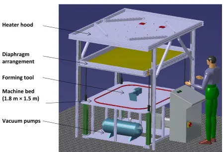
A laboratory-scale diaphragm forming machine was designed at the University of Nottingham to preform binder-stabilised dry fabrics, and is shown in Figure 1. The dimensions of the diaphragms were 1.8 m × 1.5 m. The lower diaphragm was clamped between two frames , and the upper diaphragm was fixed to the lower diaphragm using a vacuum-tight zipper seal. This arrangement was fixed to four pneumatic cylinders which were used to raise and lower the diaphragms relative to the forming tool.
A schematic of the process steps is shown in Figure 2. The fabric plies were placed on top of the lower diaphragm. The upper diaphragm was then added and the zipper seal was closed manually to encapsulate the fabric plies (Figure 2a). A vacuum was drawn between the two diaphragms to clamp the material. The diaphragm arrangement was raised to within 150 mm of infrared heaters and heated to 90 °C in order to melt the powdered binder. Once the set-point was achieved, the diaphragm arrangement was quickly lowered and draped over the tool (Figure 2b). A second vacuum (independent of the first) was then drawn between the lower diaphragm and the tool to complete the forming process (Figure 2c). The preform was left to cool to below the melting point of the binder before removing (Figure 2d). The vacuum was then released between the diaphragms and the top diaphragm was removed first, to prevent the preform from distorting or springing back. The vacuum between the lower diaphragm and the tool was released once the preform had been removed, enabling the lower diaphragm to recover before the next preforming cycle. The total cycle time was approximately 4 minutes for this laboratory setup. This time largely depends on the
7 been activated. This could potentially be reduced further by implementing forced cooling and increasing the power of the heaters.
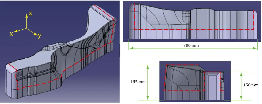
A demonstrator tool was designed, representing a section from a complex automotive structure, as shown in Figure 3. The surface shape includes regions of single and double curvature and surface features which could lead to fabric bridging.
2.2 Non-crimp fabric characterisation
All preforms were produced using two plies of FCIM359 biaxial non-crimp fabric (NCF), supplied by Hexcel, Leicester, UK. Each ply consisted of 440 gsm of carbon fibre with a 24K tow size, in a ±45° architecture [26, 27] with a pillar stitch at 0°. A small amount (6 wt%) of Momentive Epikote 05390 binder was applied between layers to stabilise the post-formed shape. The thickness of each ply was measured to be 0.4 mm, using a Vernier caliper. The in-plane shear behaviour of the FCIM359 fabric has been previously characterised by the authors using the picture frame test [28] and is presented in Figure 4. The force required to shear a fabric specimen of given dimensions was measured as a function of the shear angle. Visually monitoring the specimen during the test enabled the onset of defects to be correlated to the force/angle data. During positive shear, there is a linear rise in shear force with increasing shear angle, which corresponds to the stitch yarns being placed in tension. The shear force peaks at a shear angle of 28o. This is followed by a progressive reduction in
shear force as the shear angle increases, as stitch yarns fail successively. Complete failure of the stitches occurs at 43o, after which the shear force begins to rise again due to shear
locking of the primary yarns. During negative shear, the shear compliance curve
8 out-of-plane buckling at higher shear angles, which was observed at shear angles greater than 50o.
2.3 Diaphragm characterisation
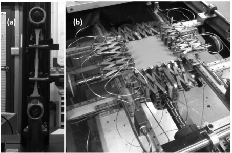
The diaphragms were made from Supervac silicone sheet with 50 Shore A hardness, supplied by Silex Ltd, UK. A series of mechanical tests were performed on coupons to characterise the in-plane behaviour of the diaphragm. The thickness of the diaphragm was 1.56 mm. Uniaxial tensile tests were performed on a universal testing machine at a strain rate of 0.03 s-1. The tensile force was recorded by a 5 kN load cell and a balanced travelling
extensometer was used to measure the axial strain (see Figure 5a). The cross-section of the sample was 5.00 mm × 1.56 mm, and rubber-faced jaws were used to reduce stress
concentrations due to clamping.
A Flexible Biaxial Film Tester [29] was used to perform equibiaxial tensile tests and planar shear tests on the silicone diaphragms (see Figure 5b). The machine consisted of a
horizontal biaxial frame driven by two independent leadscrews and controlled by a LabView interface. The specimen dimensions for biaxial tests were 75 mm × 75 mm, clamped by 7 miniature pneumatic grips along each edge. Load cells are integrated into the two central grips to record the forces, and strain was measured using a non-contact video tracking system which relied on a series of markers applied to the top surface of the specimen. The equibiaxial tensile tests were performed by applying the same displacement rate,
corresponding to a strain rate of 0.03 s-1, to each grip. The pure shear test was performed by
9 2.4 Friction characterisation
Friction testing was based on relative movement between a sled and a supporting table (ASTM D1894, ISO8295). Material specimens were attached to the surfaces of the sled and the table to represent the surface pairings in the forming process, including tool-diaphragm, diaphragm-fabric, and fabric-fabric. The sled was loaded with a weight to apply a normal force at the contact surface. The tangential force required to move the sled at a constant velocity across the table was measured. The coefficient of friction was calculated from the ratio of the tangential (pulling)force and the normal force.
Typical raw data for the measured pulling force show a steep increase until a maximum is reached, then a decrease and convergence to a limit value. Using the peak pulling force, the coefficient of static friction of the respective surface pairing can be calculated, while the limit value gives the coefficient of sliding friction. Here, coefficients of sliding friction will be used from five repeat specimens for each surface pairing.
3 Double diaphragm forming process simulation
3.1 DDF process model
10 density of the fabric was assumed to be 1200 kg/m3, while the density of the diaphragm was
1600 kg/m3. All parts of the tooling (tool and machine bed) were modelled as rigid bodies. A
penalty contact algorithm was used to define the behaviour at the interfaces. A Coulomb friction model was adopted for tool-diaphragm, diaphragm-fabric and fabric-fabric contacts. Average coefficients of friction used in the simulations were 0.67, 0.52 and 0.36,
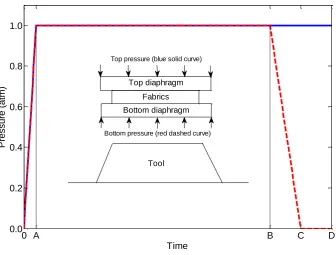
respectively, where anisotropy related to the stitching pattern in the NCF was ignored. Pressures were applied to the upper surface of the top diaphragm and the lower surface of the bottom diaphragm, as shown in Figure 7. From time A to time B, both pressures were equal in magnitude but opposite in direction to simulate the clamping force on the fabric plies generated by the vacuum between the diaphragms. Displacement boundary conditions were then applied to the edge nodes of the diaphragms to simulate the frame being
lowered to make contact with the bed of the machine. Subsequently, a pressure differential was created between the two diaphragm surfaces to simulate the vacuum being applied between the lower diaphragm and the tool. The pressure applied to the bottom diaphragm was reduced (time B to time C), drawing the diaphragm arrangement into contact with the surface of the tool. Gravity was neglected in the FE model.
3.2 NCF material model
11 derived from two components; rotation of the principal fibre yarns and tension in the intra-ply stitches:
𝐹𝑛𝑜𝑟𝑚= 𝐹𝑛𝑜𝑟𝑚𝑦𝑎𝑟𝑛 𝑟𝑜𝑡𝑎𝑡𝑖𝑜𝑛+ 𝐹𝑛𝑜𝑟𝑚𝑠𝑡𝑖𝑡𝑐ℎ (1)
where the contribution of the yarn rotation is approximated by
𝐹𝑛𝑜𝑟𝑚𝑦𝑎𝑟𝑛 𝑟𝑜𝑡𝑎𝑡𝑖𝑜𝑛 = (29.56𝛾125 − 65.56𝛾
124 + 137.06𝛾123 + 94.73𝛾122 + 112.19𝛾12)N/m (2)
and the contribution of the stitch tension, considering progressive stitch failure, is described by
𝐹𝑛𝑜𝑟𝑚𝑠𝑡𝑖𝑡𝑐ℎ = {
(2000𝛾12− 120)𝑁/𝑚 , 0.06 𝛾12 < 0.50;
(−3520𝛾12+ 2640)𝑁/𝑚 , 0.50 𝛾12 ≤ 0.75;
0 𝑁/𝑚 , 𝑒𝑙𝑠𝑒.
(3)
where γ12 is the shear angle in radians. The shear compliance of the NCF is described by
superimposing these two contributions according to Equation (1), which is presented in Figure 4. This material model is implemented in a user subroutine in Abaqus/Explicit. For validation, force-displacement data from the simulation of a picture frame test was shown to be within the bounds of the experimental data (the root mean square error was
approximately 5 %). Further validation was conducted for hemisphere forming [28], for which the constitutive relation for the NCF fabric plies was shown to suitably capture the onset of the main defect mechanisms, and local shear angles were predicted within ±5° of the experimental values.
3.3 Diaphragm material model
12 be described by a strain energy density function expressed in terms of the principal
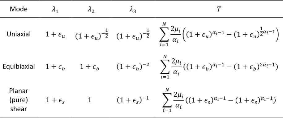
stretches, and the constitutive relations are obtained from the derivative of the strain energy with respect to stretch and by applying appropriate boundary and symmetry conditions. The nominal stress-strain relations for the three load cases, uniaxial tension (subscript 𝑢), biaxial tension (subscript 𝑏) and pure shear (subscript 𝑠) are presented in Table 1, where 𝑇 is the nominal stress, 𝜖 is the nominal strain, 𝑁 = 2 is the order of the Ogden model, and 𝛼𝑖 and 𝜇𝑖 are material constants.
A non-linear least-squares fit was performed simultaneously on the uniaxial and equibiaxial test data to establish 𝛼𝑖 and 𝜇𝑖, using the Marquard-Levenberg algorithm within Abaqus
[32]. A second order model was found to produce a satisfactory quality of fit, with virtually no improvement at higher orders. The constants from the least-squares fit are presented in Table 2, and a comparison of the model to the experimental data can be seen in Figure 8. The root mean squared error (RMSE) between the experimental data and the analytical Ogden model is 2.2 % for the uniaxial case and 5.5 % for the equibiaxial case. The pure shear data was excluded from the least-squares fit, and was used instead to further validate the model with a different mode of deformation. Figure 8 shows that the Ogden model
13 4 Results and discussion
4.1 Net shape forming
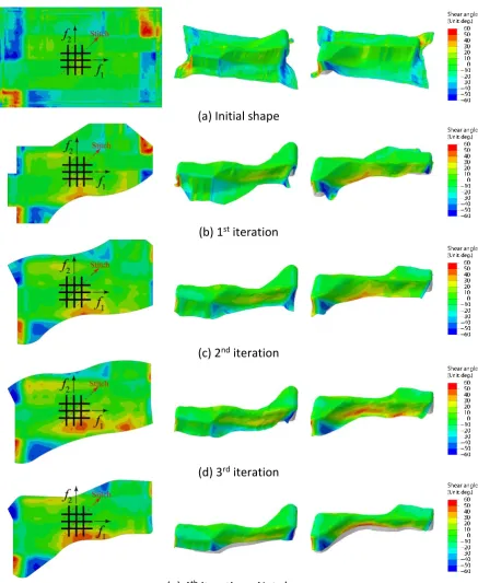
The ply shape required to form the geometry presented in Figure 3 and to achieve a net-shaped component was determined based on simulations as described above. The fibre orientation in the ply was assumed to be ±45° (where the +45° fibres were aligned with the x-axis, and the -45° fibres were aligned with the y-axis in Figure 3), as this was the most challenging fibre architecture for the chosen geometry. An initial forming simulation was run for a rectangular ply (900 mm × 550 mm, see Figure 9(a)). Finite elements positioned outside the final trim line on the formed ply were deleted. A new forming simulation was then run for the modified ply shape. Multiple iterations were required, since the initial ply shape was too large and fabric bridging occurred around the base of the tool (Figure 9(a)). The fabric therefore did not make contact with the tool in all areas, which made it difficult to determine the trim line. After four iterations, a near net-shaped preform was obtained, as shown in Figure 3. Since the DDF process can be assumed to be quasi-static, mass scaling was employed to reduce CPU time using an automatic scaling scheme in Abaqus/Explicit.
The scaling factors were selected to ensure that the kinetic energy was less than 5 % of the
internal energy throughout the analysis, enabling inertia effects to be neglected. Each
individual forming simulation took between 1.5 hours and 6 hours, depending on the size of
blank (using an Intel® CoreTM i7-3820 CPU at 3.60 GHz).
14 modified, indicating a corresponding change in the defect distribution. Although the
majority of bridging defects have been reduced by trimming the blank to a net shape, the remaining identified defects still need to be eliminated. In order to produce a high-quality DDF preform, the cause of defects in needs to be firstly understood, which is discussed in the following sections.
4.2 DDF defect formation
Fabric bridging is typically quantified by measuring the distance between the formed surface and the tool. However, bridging may be detected at the same position on the component for a 0°/90° ply and a ±45° ply, but different solutions may be required to improve the fabric conformity for the two cases. Hence, additional criteria are required to support the conventional distance measurement, in order to appropriately address the issue of fabric bridging.
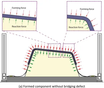
As shown in Figure 10, the resultant force from the pressure differential discussed in Figure 7 generates the forming forces to drive the fabric onto the tool surface. However, it also simultaneously generates a friction force which constrains the material sliding. Whilst a high vacuum pressure increases the forming force, a corresponding increase in in-plane friction may constrain yarn movement locally, preventing fabric-tool conformity. In particular this is a problem for deep concave features.
15 This results in the generation of considerable local tensile stresses in the primary yarns around concave sections of the tool. The tensile stress in the yarns therefore enables the location and direction of bridging yarns to be identified.
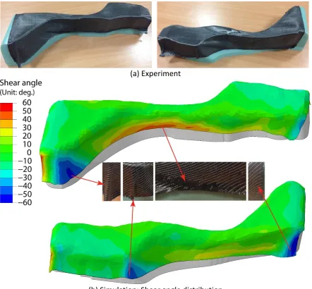
The laboratory diaphragm forming machine in Figure 1 has been used to validate the model, forming the demonstrator component presented in Figure 3. Two plies of biaxial FCIM359 NCF were cut to the net-shape shown in Figure 9(e), with the 45° fibres aligned in the x-direction and the pillar stitches running at 45°. Figure 11 indicates that there is very good agreement between simulation results and experimental observations in terms of the formed shape, including the ply outline. Similar defects are found in both data sets. Three different field variables have been used to identify the cause of defects in the simulations. These are defined as the local shear angle, the compressive strains along the principal yarns (sometimes referred to as wrinkling strains [33]) and the tensile stresses along the principal yarns.
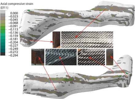
16 Compressive strains along the principal yarns, which are plotted along the two primary yarn directions in Figure 12, were relatively low (for example in comparison to previous reported work [28]). Therefore, mesoscale wrinkling due to yarn buckling (compressive strains) was limited to some minor regions on the top surface of the formed part (green contours), as indicated by the photos.
The dominant defect for DDF was observed to be fabric bridging in this study, as shown in Figure 13. Bridging was more severe along the +45° yarns in the x-direction (see Figure 13 (a)) than the -45° yarns in the y-direction (Figure 13 (b)). Comparisons with the experimental results indicate that the onset of bridging corresponds to a tensile stress in the direction of the fibres exceeding 35 MPa, is an appropriate metric for predicting the likelihood of defects caused by bridging. The axial tensile stress output from an FE solution can be used to
identify the location and orientation of yarns in tension that induce bridging defects, which may help to improve the quality of the formed shape.
In addition, some wrinkling defects were observed as a side effect of fabric bridging, due to the Poisson’s ratio contraction effects of the diaphragms. As shown in Figure 13 (a), two areas of significant fabric bridging occurred around the large curvature as the yarns in the x-direction were in tension. However, the yarns in the y-x-direction in the same areas were unconstrained, and therefore the fabric was more compliant in this direction, inducing wrinkles.
4.3 Scenarios for bridging reduction
17 DDF, the most effective solution for avoiding bridging is to delay contact between the
diaphragm assembly (two diaphragms plus fabric plies) and the tool surfaces. Rigid body movement of the yarns should be generated progressively, as the contact area increases. In order to facilitate material draw-in, darts (local cuts) were added to the optimised ply shape shown in Figure 14(a). Darts were positioned to reduce the high tensile stresses in the longitudinal yarns (x-direction), which were the main cause for occurrence of severe
bridging. Darts were cut perpendicular to these yarns in order to minimise the damage to the transverse yarns, as shown Figure 14(b). They were only permitted on the near vertical sides of the component and not on the top surface, as these fibres coincide with the primary load path. It is important to note that additional plies at different angles would be added to this single ply to manufacture the final component. Therefore the openings created by the darts would be covered by neighbouring plies, or small patches of material, to satisfy requirements of secondary load cases.
18 As shown in Figure 15, the wrinkling and over-shear induced defects decrease
simultaneously as the number of bridging fibres decreases. This indicates that bridging is the dominating defect in DDF, and a reduction in bridging may result in reduction of other forming defects. Applying suitable darts helps to overcome bridging-induced yarn wrinkling and release fabric shear locking, providing better fabric conformity. However, darts may have unexpected effects on the structural integrity of the final component and therefore should only be used away from the primary load paths.
5 Conclusions
19 6 Acknowledgements
20 7 References
1. Bersee, H.E.N., S. Lindstedt, G. Nino, and A. Beukers, Diaphragm forming of thermoset
composites, in 16th International Conference on Composite Materials. 2007: Kyoto, Japan.
2. Friedrich, K., M. Hou, and J. Krebs, Chapter 4 Thermoforming of continuous
fibre/thermoplastic composite sheets, in Composite Materials Series, D. Bhattacharyya, Editor.
1997, Elsevier. p. 91-162.
3. Pantelakis, S.G. and E.A. Baxevani, Optimization of the diaphragm forming process with
regard to product quality and cost. Composites Part A: Applied Science and Manufacturing,
2002. 33(4): p. 459-470.
4. Delaloye, S. and M. Niedermeier, Optimization of the diaphragm forming process for
continuous fibre-reinforced advanced thermoplastic composites. Composites Manufacturing,
1995. 6(3–4): p. 135-144.
5. Alshaharni, H. and M. Hojjati. Optimum processing parameters for hot drape forming of
out-of-autoclave prepreg over complex shapes using a double diaphragm technique. in 20th Internation Conference on Composite Materials. 2015. Copenhagen.
6. Bian, X.X., Y.Z. Gu, J. Sun, M. Li, W.P. Liu, and Z.G. Zhang, Effects of Processing Parameters on
the Forming Quality of C-Shaped Thermosetting Composite Laminates in Hot Diaphragm Forming Process. Applied Composite Materials, 2013. 20(5): p. 927-945.
7. Sun, J., Y. Gu, M. Li, X. Ma, and Z. Zhang, Effect of forming temperature on the quality of hot
diaphragm formed C-shaped thermosetting composite laminates. Journal of Reinforced
Plastics and Composites, 2012. 31(16): p. 1074-1087.
8. Dumont, F. and C. Weimer, 19 - Non-crimp fabric: preforming analysis for helicopter
applications, in Non-Crimp Fabric Composites, S.V. Lomov, Editor. 2011, Woodhead
Publishing. p. 449-460.
9. Leutz, D., M. Kluepfel, F. Dumont, R. Hinterhoelzl, K. Drechsler, and C. Weimer. FE‐
Simulation of the Diaphragm Draping Process for NCF on a Macro‐Scale Level. in THE 14TH INTERNATIONAL ESAFORM CONFERENCE ON MATERIAL FORMING. 2011. AIP Publishing.
10. Margossian, A., S. Bel, J. Balvers, D. Leutz, R. Freitas, and R. Hinterhoelzl, Finite element
forming simulation of locally stitched non-crimp fabrics. Composites Part A: Applied Science
and Manufacturing, 2014. 61: p. 152-162.
11. Luby, S. and E. Bernardon, Design of fabric preforms for double diaphragm forming, in Ninth
DOD(NASA)FAA Conference on Fibrous Composites in Structural Design. 1995: Draper (Charles
Stark) Lab., Inc.; Cambridge, MA, United States. p. 1175-1184.
12. Krebs, J., K. Friedrich, and D. Bhattacharyya, A direct comparison of matched-die versus
diaphragm forming. Composites Part A: Applied Science and Manufacturing, 1998. 29(1–2): p.
183-188.
13. Krebs, J., D. Bhattacharyya, and K. Friedrich, Production and evaluation of secondary
composite aircraft components—a comprehensive case study. Composites Part A: Applied
Science and Manufacturing, 1997. 28(5): p. 481-489.
14. Gutowski, T.G., G. Dillon, S. Chey, and H. Li, Laminate wrinkling scaling laws for ideal
composites. COMPOSITES MANUFACTURING, 1995. 6(3): p. 123-134.
15. Bersee, H.E.N. and A. Beukers, Diaphragm forming of continuous fibre reinforced
21 Upilex-R® diaphragms. Composites Part A: Applied Science and Manufacturing, 2002. 33(7): p.
949-958.
16. O'Brádaigh, C.M., R.B. Pipes, and P.J. Mallon, Issues in diaphragm forming of continuous fiber
reinforced thermoplastic composites. Polymer Composites, 1991. 12(4): p. 246-256.
17. Chen, S., L.T. Harper, A. Endruweit, and N.A. Warrior, Formability optimisation of fabric
preforms by controlling material draw-in through in-plane constraints. Composites Part A:
Applied Science and Manufacturing, 2015. 76: p. 10-19.
18. Hallander, P., M. Akermo, C. Mattei, M. Petersson, and T. Nyman, An experimental study of
mechanisms behind wrinkle development during forming of composite laminates. Composites
Part A: Applied Science and Manufacturing, 2013. 50: p. 54-64.
19. Hallander, P., J. Sjölander, and M. Åkermo, Forming induced wrinkling of composite laminates
with mixed ply material properties; an experimental study. Composites Part A: Applied
Science and Manufacturing, 2015. 78: p. 234-245.
20. Yu, W.-R., P. Harrison, and A. Long, Finite element forming simulation for non-crimp fabrics
using a non-orthogonal constitutive equation. Composites Part A: Applied Science and
Manufacturing, 2005. 36(8): p. 1079-1093.
21. Creech, G. and A. Pickett, Meso-modelling of non-crimp fabric composites for coupled drape
and failure analysis. Journal of materials science, 2006. 41(20): p. 6725-6736.
22. Sirtautas, J., A.K. Pickett, and P. Lépicier, A mesoscopic model for coupled drape-infusion
simulation of biaxial Non-Crimp Fabric. Composites Part B: Engineering, 2013. 47: p. 48-57.
23. Sorrentino, L. and C. Bellini, Potentiality of Hot Drape Forming to produce complex shape
parts in composite material. The International Journal of Advanced Manufacturing
Technology, 2015: p. 1-10.
24. Sjölander, J., P. Hallander, and M. Åkermo, Forming induced wrinkling of composite laminates:
A numerical study on wrinkling mechanisms. Composites Part A: Applied Science and
Manufacturing, 2016. 81: p. 41-51.
25. Front matter, in Non-Crimp Fabric Composites, S.V. Lomov, Editor. 2011, Woodhead
Publishing. p. i-iii.
26. O'Sullivan, L., Characterization and simulation of structural fabrics–Part 2: Evaluating process
simulation software in a product development cycle. Reinforced Plastics, 2015. 59(6): p.
305-309.
27. McGregor, O.P.L., S. Chen, L.T. Haper, A. Endruweit, and N.A. Warrior, Defect characterisation
and selective stitch removal in non-crimp fabrics, in International Conference SAMPE Europe.
2015: Amiens.
28. Chen, S., O.P.L. McGregor, L.T. Harper, A. Endruweit, and N.A. Warrior, Defect formation
during preforming of a bi-axial non-crimp fabric with a pillar stitch pattern. Composites Part
A: Applied Science and Manufacturing.
29. Buckley, C., D. Turner, A. Dorfmann, and R. Muhr, Application of flexible biaxial testing in the
development of constitutive models for elastomers. Constitutive Models for Rubber.
Rotterdam: AA Balkema, 1999: p. 59-64.
30. Peng, X., J. Cao, J. Chen, P. Xue, D. Lussier, and L. Liu, Experimental and numerical analysis on
normalization of picture frame tests for composite materials. Composites Science and
22
31. Ogden, R. Large deformation isotropic elasticity-on the correlation of theory and experiment
for incompressible rubberlike solids. in Proceedings of the Royal Society of London A: Mathematical, Physical and Engineering Sciences. 1972. The Royal Society.
32. Twizell, E. and R. Ogden, Non-linear optimization of the material constants in Ogden's
stress-deformation function for incompressinle isotropic elastic materials. The Journal of the
Australian Mathematical Society. Series B. Applied Mathematics, 1983. 24(04): p. 424-434.
33. Chen, S., O.P.L. McGregor, L.T. Harper, A. Endruweit, and N.A. Warrior, Defect formation
during preforming of a bi-axial non-crimp fabric with a pillar stitch pattern. Composites Part
A: Applied Science and Manufacturing, 2016. 91: p. 156-167.
[image:22.595.75.533.353.544.2]8 Tables
Table 1: Stress-strain relations for three load cases using the Ogden hyperelastic material model; 1, 2, 3 indicate the principal stretches; T is the nominal stress.
Mode 𝜆1 𝜆2 𝜆3 𝑇
Uniaxial 1 + 𝜖𝑢 (1 + 𝜖𝑢)−12 (1 + 𝜖𝑢)−12 ∑2𝜇𝛼𝑖
𝑖 ((1 + 𝜖𝑢)
𝛼𝑖−1− (1 + 𝜖𝑢)12𝛼𝑖−1)
𝑁
𝑖=1
Equibiaxial 1 + 𝜖𝑏 1 + 𝜖𝑏 (1 + 𝜖𝑏)−2 ∑ 2𝜇𝑖
𝛼𝑖 ((1 + 𝜖𝑏)𝛼𝑖−1− (1 + 𝜖𝑏)2𝛼𝑖−1) 𝑁
𝑖=1
Planar (pure) shear
1 + 𝜖𝑠 1 (1 + 𝜖𝑠)−1 ∑
2𝜇𝑖
𝛼𝑖 ((1 + 𝜖𝑠)𝛼𝑖−1− (1 + 𝜖𝑠)𝛼𝑖−1) 𝑁
[image:22.595.75.519.631.687.2]𝑖=1
Table 2: Material constants for Ogden hyperelastic model used to describe the deformation of the silicone diaphragm material.
Diaphragm material 𝜇1 (Pa) 𝛼1 𝜇2 (Pa) 𝛼2
23 9 Figures
[image:23.595.75.527.99.405.2]Figure 1: Details of the diaphragm forming machine.
Figure 2: Schematic of the double diaphragm forming process Heater hood
Diaphragm arrangement
Machine bed (1.8 m × 1.5 m)
Vacuum pumps Forming tool
a)
c)
b)
[image:23.595.71.500.463.715.2]24 Figure 3: Tool geometry for the case study component. Red lines indicate the trimmed edge of the final component.
Figure 4: Summary of the shear resistance curve for FCIM359 biaxial non-crimp fabric; experimental data and fit according to Equations (1) to (3). Reproduced from [33].
-1.5 -1 .0 -0.5 0 .0 0.5 1 .0 1.5
-800 -600 -400 -200 0 200 400 600 800 1000
Shear angle / rad
N o rm a lise d sh e a r fo rce / ( N /m )
[image:24.595.77.462.333.608.2]25 Figure 5: Photographs showing test rigs for (a) uniaxial tensile testing and (b) biaxial tensile testing of silicone diaphragms.
Figure 6: FE model of double diaphragm forming. A quadrant from the two diaphragms and the fabric stack has been removed for clarity. Arrows indicate the direction of the applied pressure (always normal to the surface of the diaphragms).
(a)
(b)
Tool
Upper diaphragm
Lower diaphragm Fabric stack
[image:25.595.73.492.428.701.2]26 Figure 7: Definition of pressure applied to the diaphragms in the FE model.
0 A B C D
0.0 0.2 0.4 0.6 0.8 1.0
Time
P
re
ssu
re
(
a
tm
)
Tool
Bottom pressure (red dashed curve)
Bottom diaphragm Fabrics Top diaphragm
27 (a) Uniaxial tension
(b) Equibiaxial tension
[image:27.595.162.435.69.704.2](c) Planar (pure) shear
Figure 8: Data used to characterise the deformation behaviour of the silicone diaphragms. Experimental data is presented for three load cases and compared to analytical solutions and Abaqus simulations using the Ogden model.
0% 100% 200% 300% 400% 500% 600% 0.0 1.0 2.0 3.0 4.0 5.0 6.0 Strain S tr e ss (M P a ) Experimental data Analytical model FE simulation
0% 20% 40% 60% 80% 100%
28 (a) Initial shape
(b) 1st iteration
(c) 2nd iteration
(d) 3rd iteration
[image:28.595.79.517.90.624.2](e) 4th iteration - Net shape
29 (a) Formed component without bridging defect
[image:29.595.118.478.68.374.2]30 (a) Experiment
(b) Simulation: Shear angle distribution
[image:30.595.78.521.70.480.2]31 (a) Axial compressive strain along +45° yarns in x-direction
[image:31.595.74.515.69.392.2]32 (a) Axial tensile stress along +45° yarns in x-direction
[image:32.595.75.511.71.403.2]33
[image:33.595.76.546.107.460.2](a) Without darts (b) With darts
34 (a) Photographs from experiment
(b) Shear angle distribution
(c) Axial compressive strain in longitudinal fibres
(d) Axial compressive strain in transverse fibres
(e) Axial tensile stress in longitudinal fibres
[image:34.595.72.545.104.721.2]