Master Thesis
Assessing the Security of
IEC 60870-5-104 Implementations
using Automata Learning
Max Kerkers
Supervisors:
prof. dr. ir. B.R.H.M. (Boudewijn) Haverkort - University of Twente dr. A.K.I. (Anne) Remke - University of Twente
J.J. (Justyna) Chromik MSc - University of Twente D. (Dennis) Waalewijn MSc - KPMG
3
Abstract
5
Acknowledgements
First of all, I would like to express my gratitude to Juystyna Chromik from the University of Twente, for the many discussions about my research, arranging meetings with Stedin and Cogas so that I could perform research there, the thorough reading through everything I wrote and the really helpful feedback. I would also like to thank Boudewijn Haverkort, as my first supervisor, and Anne Remke for joining my graduation committee.
I am very grateful that I could write my thesis as part of the KPMG Cyber team. Particularly, I would like to thank Dennis Waalewijn as my main supervisor from KPMG and Martijn Sprengers for helping me to come up with the subject of my research. Also, I would like to express my appreciation for my co-interns, who provided the occasional necessary distraction.
Furthermore, I would like express my gratitude to Joey Godefrooi and Pascal Everste from Stedin, for providing me access to one of their testing stations, where I could perform research. I would also like to thank Gerard Geist from Cogas and Ronald Robbertsen from Datawatt, for proving me with an RTU to perform tests on.
7
Contents
1 Introduction 17
2 Industrial Control Systems 21
2.1 History of ICS . . . 21
2.2 ICS components . . . 23
2.3 Security of ICS . . . 25
2.3.1 Security attributes . . . 25
2.3.2 Security weaknesses . . . 26
2.3.3 Example attack scenario . . . 28
2.4 IEC 60870-5-104 . . . 28
2.4.1 Structure . . . 30
2.4.2 State transition diagram . . . 34
2.4.3 IEC-104 parameters . . . 36
2.5 Conclusion . . . 36
3 Representing protocols 37 3.1 Protocol implementation . . . 37
3.2 Formal protocol description . . . 39
3.2.1 Deterministic finite automaton . . . 40
3.2.2 Mealy machines . . . 41
3.2.3 Protocol inputs (alphabet) . . . 41
3.3 Automata learning . . . 42
3.4 Algorithm . . . 43
3.4.1 Example . . . 46
3.5 Automata comparison . . . 47
4 Methodology 49
4.1 Set-up . . . 49
4.2 Learner . . . 51
4.2.1 LearnLib . . . 51
4.2.2 Design of the Alphabet . . . 52
4.3 Mapper . . . 52
4.4 Teacher . . . 54
4.4.1 Subjects under Test . . . 54
4.5 Checker . . . 56
4.6 Conclusion . . . 58
5 Results 59 5.1 Simulators . . . 59
5.1.1 Axon Test . . . 60
5.1.2 Mitra Software IEC 870-5-104 Simulator . . . 61
5.1.3 Siemens IEC-Test . . . 62
5.2 Real devices . . . 63
5.2.1 Datawatt D05-Lite . . . 63
5.2.2 Sprecher Sprecon-E-C-92 . . . 65
5.3 Additional considerations . . . 66
5.4 Conclusion . . . 66
6 Conclusions 69 6.1 Discussion . . . 73
6.2 Future Work . . . 73
6.3 Recommendations . . . 74
A IEC-104 ASDU command types 81 A.1 Process information in monitoring direction . . . 81
A.2 Process telegrams with long time tag (7 octets) . . . 82
A.3 Process information in control direction . . . 82
A.4 Command telegrams with long time tag (7 octets) . . . 83
A.5 System information in monitoring direction . . . 83
A.6 System information in control direction . . . 83
A.7 Parameter in control direction . . . 83
9
List of Figures
2.1 Generations in development of ICS/SCADA [12] . . . 22
2.2 Overview scopes ICS, SCADA and DCS . . . 23
2.3 Typical Industrial Control System . . . 24
2.4 Architecture of IEC TC57 Information Exchange Standards [10] . . . 29
2.5 Application Protocol Data Unit (APDU) formats . . . 32
2.6 Application Service Data Unit (ASDU) structure . . . 33
2.7 State transition diagram for Start/Stop procedure (controlled station) [42] . 35 3.1 Example protocol . . . 38
3.2 Possible implementations . . . 38
3.3 Deterministic finite automaton . . . 40
3.4 Mealy machine . . . 41
3.5 Automata learning setup . . . 42
3.6 Observation Tables and automata learnt from Example . . . 47
4.1 Test Set-up . . . 50
4.2 Example of concrete mapping from I[C SC NA] . . . 53
4.3 Test Set-up at Stedin . . . 55
4.4 Test Set-up Datawatt . . . 56
4.5 Automaton deduced from IEC-104 State Transition Diagram (Figure 2.7) . 57 5.1 Automaton learnt from Axon Test simulator . . . 60
5.2 Automaton learnt from Mitra Software IEC 870-5-104 Simulator . . . 61
5.3 Automata learnt from IEC-Test Simulator . . . 62
5.4 Automaton learnt from Datawatt implementation . . . 63
11
List of Tables
2.1 Order of importance of security attributes per sector . . . 26
2.2 OSI layers . . . 30
2.3 ASDU types defined in IEC 60870-5-104 . . . 33
2.4 IEC-104 parameters and default values [42] . . . 36
4.1 Alphabet . . . 52
13
List of Abbreviations
APCI Application Protocol Control Information. 30, 53
APDU Application Protocol Data Unit. 36, 53, 54
ARP Address Resolution Protocol. 27
ASDU Application Service Data Unit. 30, 34, 52–54, 59, 64, 73, 74
DCS Distributed Control Systems. 23
DFA Deterministic Finite Automaton. 40, 41, 43, 47
DNP3 Distributed Network Protocol. 28, 54
FSM Finite State Machine. 3, 39, 40
HMI Human-Machine Interface. 24, Glossary: HMI
ICS Industrial Control Systems. 3, 17–19, 21, 23, 25–28, 36, 56, 66, 72, 73
IEC International Electrotechnical Commission. 3, 18, 19, 26–28, 30, 36, 56, 66, 69–71, 73, 74
IEC-101 IEC 60870-5-101. 28, 30, 54, 60
IEC-104 IEC 60870-5-104. 21, 27, 28, 30, 48, 51–54, 56, 60, 61, 63, 65, 70–74
IED Intelligent Electronic Device. 24,Glossary: IED
IoT Internet of Things. 25
LAN Local Area Network. 21
MAC Media Access Control. 27
MMS Manufacturing Message Specification. 27, 73
MTU Master Terminal Unit. 24,Glossary: MTU
PLC Programmable Logic Controller. 24, 56,Glossary: PLC
RTU Remote Terminal Unit. 21, 23, 24, 28, 33, 55, 56, 63–67, 70, 71, 73, 74, Glossary:
RTU
SCADA Supervisory Control And Data Acquisition. 15, 17, 23, 28
SSH Secure Shell. 40
SUT Subject Under Test. 42, 46, 51, 54
TCP Transmission Control Protocol. 23, 25, 27, 28, 30, 36, 39
15
Glossary
control server Host of the supervisory control software. 24
historian Database with records of all process information. 24
HMI (human-machine interface) Interface to provide human operators with
informa-tion and control. 24
IED (intelligent electronic device) Sensor or actuator that is able to acquire data,
communicate to other devices and perform local processing and control. 24
implementation The realisation of a specification into an actual system. 37
MTU (master terminal unit) Device acting as master for the communication in SCADA
system. 24
PLC (programmable logic controller) Special purpose data acquisition and control
unit provided with a communication interface. 24
protocol “A formal description of messages to be exchanged and rules to be followed for two or more systems to exchange information.” [20]. 15, 37
RTU (remote terminal unit) Special purpose data acquisition and control unit
pro-vided with a communication interface. 21, 24
specification The complete formal description of a protocol. 15, 37
standard “Document, established by consensus and approved by a recognised body, that
17
Chapter 1
Introduction
In 2007, the Idaho National Labratories conducted an experiment that demonstrated that, when having access to the control network, it is possible to physically damage components that are used in power grids [35, 40]. This experiment was referred to as the Aurora generator test and it showed that it was possible to physically destroy a power generator by attacking its process control system. This control system is also used in operational power plants.
These Industrial Control Systems (ICS), such as Supervisory Control And Data Acqui-sition (SCADA) systems, are used to control and monitor (critical) infrastructures. These SCADA systems often control geographically distributed facilities such as power generation and distribution, water treatment, and oil and gas distribution. Also, ICS are found in systems for, e.g., heating, ventilation and air conditioning, as well as lighting or physical security.
Most of these systems were designed decades ago as standalone systems and were not connected to other networks. However, as these systems have become more connected over the years, threats from outside the network cannot be disregarded anymore. Even if the network of some industry, e.g., a power plant, is not connected to the internet, it can still be infected with malicious software by a device from outside the network. For example, this happened to an Iranian nuclear power plant, when a computer that was infected with the Stuxnet virus was connected to the trusted network of the nuclear power plant [26].
be a serious threat to the process, if the device with the implementation flaw is important to the system.
This research investigates implementations of the IEC 60870-5-104 protocol, which is an ICS protocol that is mainly used in power distribution. This protocol was chosen, because it is crucial for the communication between the control stations and distribution stations in Europe, even when these distribution station use newer protocols internally. Although this protocol is widely used in Europe, not much research has been performed on its security [28]. In the research for this thesis a tool is developed that is capable of inferring a formal representation from an IEC 60870-5-104 implementation. The source code of this tool can be found on GitHub [24].
The goal of this research is to provide a method to formally represent implementations of IEC 60870-5-104, as well as to provide means to analyse and compare the obtained representations and use them to assess the security attributes of IEC 60870-5-104. To achieve these mentioned goals, the following research questions are addressed in this master thesis:
RQ1: How can implementations of IEC 60870-5-104 be represented formally?
The goal of this research question is to propose a method to generate formal representations from the implementations of IEC 60870-5-104. To achieve this goal, two sub-questions need to be addressed first:
a) Which methods exist to generate formal representations?
b) What method is suitable for formally representing protocols?
RQ2: To what extent do implementations of IEC 60870-5-104 comply to their standard?
The goal of this research question is to provide an analysis of implementations of the IEC 60870-5-104 protocol and to compare them to the standard. The method that is obtained from the first research question can be used to represent these implementations formally. In order to be able to achieve this goal, these sub-questions need to be addressed first:
a) What implementations of IEC 60870-5-104 are available?
b) How can the IEC 60870-5-104 standard be formally represented?
Chapter 1. Introduction 19
d) What do the findings from these questions tell about the IEC 60870-5-104 standard?
If these comparisons yield differences between implementations of the IEC 60870-5-104 specification, this indicates that the specification contains ambiguities and obscurities. These differences are described and their significance is examined by, e.g., investigating if a transition that can be circumvented in one of the implementation could cause incorrect behaviour.
RQ3: What information security attributes are violated in the implementations that were researched in the second research question and how?
The goal of this research question is to perform an assessment of the information security attributes based on the findings from the second research question. Before violations of these security attributes can be found, the following sub-question needs to be addressed:
a) What information security attributes are relevant in ICS?
The first contribution of this thesis is the described tool that can be used to infer formal representations automatically from any implementation of IEC 60870-5-104. The second contribution is the comparison and analysis of these formal representations that this tool generates. Another contribution is the assessment of the information security attributes of the implementations. Finally, the last contribution is the analysis of the specification itself.
21
Chapter 2
Industrial Control Systems
This chapter provides background information about Industrial Control Systems (ICS) and their security. First, section 2.1 provides some historical background on the development of ICS. Section 2.2 defines the components of ICS, as they are used in the rest of this thesis. Then, background information about the security of ICS is given in section 2.3. Section 2.4 describes the protocol IEC 60870-5-104 (IEC-104) that is examined in the rest of this research. Finally, this chapter is concluded with several final remarks in section 2.5.
2.1
History of ICS
Thakur [44] divides the historical development of ICS into three generations: (i) the mono-lithic generation (Figure 2.1a), (ii) the distributed generation (Figure 2.1b) and (iii) the networked generation (Figure 2.1c).
In the monolitic generation, ICS consisted of a mainframe computer with a dedicated serial line to each remote terminal unit (RTU) in the system. Each ICS vendor had developed their own devices that were using their own proprietary protocols. This resulted globally in about 200 proprietary protocols that were not interoperable [22].
In the distributed generation, ICS were not controlled by a single mainframe anymore. Instead, the mainframe was replaced by a local area network (LAN) of multiple systems. In this LAN each of the systems had a specific task. Communication between this LAN and the RTUs still happened over dedicated lines, but now there was one single computer in the LAN with the task of communicating with the RTUs. On the LAN itself the devices became connected using standard protocols, while for the communication with the RTUs proprietary protocols were still used.
(a)First generation: monolithic (b) Second generation: distributed
[image:22.612.118.527.166.563.2](c)Third generation: networked
2.2. ICS components 23
over packet switched networks using standard protocols like, e.g., TCP/IP [11]. Between the legacy RTUs, that are not capable of communicating over the standard protocols, a communication server is placed, which translates the communication. As the protocols in this architecture are based on open standards, interoperability between systems of different vendors became possible.
2.2
ICS components
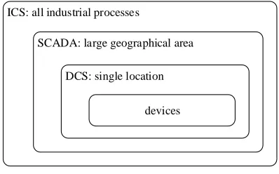
ICS is the most comprehensive term for several types of control systems, including Super-visory Control And Data Acquisition (SCADA) systems and Distributed Control Systems (DCS) [39]. In Figure 2.2 the used terminology is visualised. The term SCADA is used to describe systems spanning a large geographical area, whereas DCS describes systems con-trolling a single location. This is denoted in Figure 2.2 by presenting DCS as a subsystem of SCADA. Note, that DCS do not have to be a part of a SCADA system; it can also be a standalone system.
ICS: all industrial processes
SCADA: large geographical area
DCS: single location
[image:23.612.188.387.365.489.2]devices
Figure 2.2: Overview scopes ICS, SCADA and DCS
WAN Communication link
RTU / PLC IED Field network 1
RTU / PLC IED Field network 2
Control server
MTU
[image:24.612.120.529.137.281.2]Historian HMI Control network
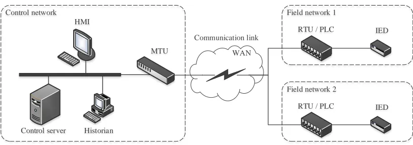
Figure 2.3: Typical Industrial Control System
Field network
The field network comprises the remote location that is controlled. Components that gen-erally can be found in a field network are: a remote terminal unit (RTU), a programmable logic controller (PLC) and an intelligent electronic device (IED) [5, 33, 14]. The primary function of the RTU is to communicate with the MTU in the control network. Further-more, an RTU can also act as a PLC in the field network. Attached to a PLC there can be several IEDs, from which the PLC collects data and to which it can send commands.
Control network
The control network comprises the location from where the entire system is controlled. Components that generally can be found in control networks are: a control server, a human-machine interface (HMI), a master terminal unit (MTU) and a historian. The control server controls this network and hosts the control software. The MTU sends control data to the RTUs and presents gathered data to the HMI. This HMI can be used by human operator to obtain information and to control the system. Lastly, the historian contains a database with all prior process information.
Communication link
2.3. Security of ICS 25
(WAN).
2.3
Security of ICS
As described in section 2.1, ICS historically were structured so that they mainly depended on two forms of protection [5]: (i) the so-called air gap that isolated the systems from other networks, and (ii) the reliance of vendors on security through obscurity. This latter means that vendors believed that their systems would be safe as long as they would keep the information about them secret.
However, in the latest generation, ICS have become more interconnected, as a result of which protecting ICS became an even greater challenge [11]. Before this generation, an attacker had to acquire physical access in order to intrude the ICS, because there were only dedicated serial lines. Nowadays, the attacker would be able to attack the ICS remotely by compromising only a single machine that has access to the ICS’ network.
Because of the standardisation of protocols and the increase in use of generic network devices,security through obscurity cannot be considered as a protection mechanism. In the endeavour of reducing cost and increasing efficiency, more low cost commercial off-the-shelf devices, like Windows computers, are used in ICS [5]. Also, the universal TCP/IP protocol stack is adapted more often.
Additionally, with the current tendency where all devices become increasingly connected to the internet, resulting in the so-called Internet of Things (IoT), the attack surface became larger for ICS [21]. Also, with the development of search engines that index both ICS and IoT devices, these devices have become easier to find over the internet. Examples of these are Shodan [38] and Censys [7], in which a protocol name can be entered, which results in all indexed devices that are accessible through the internet and recognised to use that protocol.
The rest of this section, first, describes the security attributes as they apply to ICS. Then, security weaknesses in ICS are addressed and, finally, an example attack scenario is described.
2.3.1 Security attributes
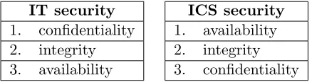
processes that depend on immediate feedback. When these processes are not available, this could result in significant (financial) loss for the operator. On the contrary, confidentiality generally is less important in ICS, as the messages sent in those are relatively predictable and not containing much private information.
[image:26.612.216.435.261.319.2]This difference is important, as this means that it would be a much bigger issue if an attacker would be able to shut down or disrupt a protocol in an ICS, than it would be for IT systems. Therefore, it is essential that the systems and protocols do not get disturbed.
Table 2.1: Order of importance of security attributes per sector
IT security
1. confidentiality 2. integrity 3. availability
ICS security
1. availability 2. integrity 3. confidentiality
2.3.2 Security weaknesses
The security weaknesses found in ICS are caused either by lack of sufficient security mech-anisms or they origin in design [25]. The first ones often are known but not implemented either due to the costs of deploying security measures, or because of difficulties in applying them in legacy systems [28]. The second ones can have different causes, like weaknesses in the way a network is built or that there are security mechanisms available but not used. Even more particularly, these design vulnerabilities can origin in incorrect implementations of ICS specific protocols.
Most communication between ICS devices follow ICS specific protocols [35]. As seen in the last section, the availability of these protocols is crucial for the functioning of the ICS. That means that if there is a vulnerability in the implementation of such a protocol in a device in the ICS, this is a vulnerability for the entire ICS. Therefore, attacks on ICS protocols should be considered a significant threat to ICS. In the rest of this section several examples are given to show that attacks on ICS protocols are possible in practice. After that, the ICS protocol IEC 60870-5-104 is introduced in section 2.4 and examined in the rest of this research.
2.3. Security of ICS 27
Most of the protocols used in ICS, such as also IEC-104, do not contain any form of cryptographic protection [35]. Also, most ICS protocols use weak or no authentication and integrity checks. This enables conducting several types of attacks on these protocols. Rrushi [35] describes three of these types of attacks:
man-in-the-middle attack where the attacker obtains access to the network and can
intercept all messages between two nodes in the network;
malicious machine code upload attack where the attacker is able to use the ICS
pro-tocol to upload malicious machine code to a process control system;
denial of services attack where the attacker is able to disrupt connections to specific devices in the network.
For example, Kang et al. present an attack on an ICS protocol that is caused by the lack of authentication [23]. They describe a man-in-the-middle attack on the ICS protocol IEC 61850, which is also mainly used in power grids. In order to perform this attack they use the Address Resolution Protocol (ARP) that is used to resolve IP addresses into MAC addresses. By spoofing the table that is used to resolve these addresses, they are able to route all traffic in the ICS protocol via an attacker. Kang et al. use this ARP spoofing to man-in-the-middle IEC 61850’s communication service Manufacturing Message Specification (MMS). Due to the lack of authentication, the attackers are able to intercept the sent MMS messages and alter them. As IEC-104 also misses authentication, it would also be possible to conduct a similar attack on IEC-104.
Furthermore, Zhu et al. [47] describe several attacks on the implementations of pro-tocols used in ICS. For example, they describe several denial of service attacks that ex-ploit vulnerabilities in the implementation of TCP/IP in Windows systems that were not patched. Also, they describe a vulnerability in an implementation of MMS, i.e. it does not handle all malformed packets correctly, which makes a remote denial of service attack possible.
More generally, for every protocols that runs on top of TCP/IP, the absence of adequate authentication makes it possible to spoof TCP packets and set wrong flags [35]. This could be used by an attacker to perform a denial of service attack, as wrong flags could cause a TCP connection to terminate.
2.3.3 Example attack scenario
Before the details on IEC-104 are given, this section first provides an example of an attack scenario that could be performed with the ICS security weaknesses that are investigated in this research. This attack scenario consists of the following steps:
1. Achieve (one-time) access to the control network (for example with an infected USB-stick).
2. Send messages to multiple RTUs to set unsafe conditions.
3. Make substations unreachable by sending a specific stream of messages that exploits the incorrect implementation.
When these steps are executed, the processes on multiple sites are in unsafe conditions and an operator would not be able to resolve that remotely. This could have serious consequences if the operator is not able to reach each of the sites before accidents occur.
These first two steps are not in the scope of the research in this thesis, as the first step can be performed in multiple different ways and the second step requires regular use of the protocol. Therefore, the focus of this research is on the third step of this example attack scenario.
2.4
IEC 60870-5-104
As stated in the Introduction, this research focuses on IEC 60870-5-104 [42]. This is one of the protocols in the IEC 60870 collection of standards that was developed by Technical Committee 57 (TC57) of the International Electrotechnical Commission (IEC) [28]. The standards in IEC 60870 were developed between 1988 and 2000 for the transmission of SCADA telemetry control data. These standards describe the protocols that are currently used in the European electrical industry [9]. Next to that, they are also used by some water and gas industries in Europe.
As Figure 2.4 shows, both IEC 60870-5-101 and -104 are used for the communication between the control centre and the substations. IEC-104 is the TCP/IP version of the older serial protocol, IEC 60870-5-101 (IEC-101) [30]. IEC-101 defines all functionality and data objects that are necessary for telecontrol applications over wide areas, such as communication between electrical control station and substation systems [9].
2.4. IEC 60870-5-104 29
that is derived from IEC-104 during its development and is used mainly in North-America). Therefore, more research has to be performed on vulnerabilities in IEC-104.
Technical specification IEC TS 60870-5-7 [43] defines an implementation of IEC 62351 to provide security and authentication to IEC-104. The purpose of this technical specification is to make it possible to verify that IEC-104 messages were sent by an authorised user and that they were not modified by a third party. However, due to implementation costs, this technical specification is not implemented in many systems.
[image:30.612.389.533.300.415.2]2.4.1 Structure
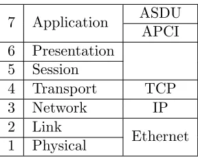
Table 2.2: OSI layers
7 Application ASDU APCI 6 Presentation
5 Session
4 Transport TCP
3 Network IP
2 Link
Ethernet 1 Physical
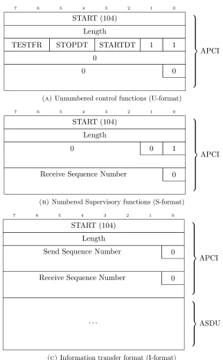
IEC-104 describes two different layers that can be placed in the application layer (layer 7) of the OSI-model [42]. As shown in Table 2.2, the bottom one is the Application Protocol Control Information (APCI) layer. The APCI layer lays on top of the TCP layer and can has three different of message formats: Unnum-bered control functions (U-format), numUnnum-bered Supervi-sory functions (S-format) and the Information transfer format (I-format). On top of the APCI layer is the Ap-plication Service Data Unit (ASDU) layer. This layer is derived from the message structure defined in IEC-101
and it is only used in I-format messages. The purpose and structure of these two layers is examined next.
As can be seen in Figure 2.5, the first two bytes of each of the three IEC-104 message formats have the same purpose. The first byte indicates that it is an IEC-104 message and this byte always the decimal number 104. The second byte indicates the length of the rest of the message, i.e. the length of the message without the first two bytes. For U-format and S-format messages, this length should always be 4.
U-format messages (Figure 2.5a) either describe activation or confirmation and have three types: STARTDT, STOPDT and TESTFR. The STARTDT (start data transfer) type is to set up a connection, the STOPDT (stop data transfer) to tear down the connec-tion and the TESTFR (test frame) is to test if the connecconnec-tion is still active.
S-format messages (Figure 2.5b) are used to confirm up to which I-format message is received.
2.4. IEC 60870-5-104 31
0 1 2 3 4 5 6 7 START (104) Length
TESTFR STOPDT STARTDT 1 1
0 0 0 APCI
(a) Unnumbered control functions (U-format)
0 1 2 3 4 5 6 7 START (104) Length
0 0 1
Receive Sequence Number 0
APCI
(b)Numbered Supervisory functions (S-format)
0 1 2 3 4 5 6 7 START (104) Length
Send Sequence Number 0
Receive Sequence Number 0
APCI . . . ASDU
[image:32.612.163.485.120.638.2](c)Information transfer format (I-format)
2.4. IEC 60870-5-104 33 0 1 2 3 4 5 6 7
Type Identification (TypeID)
Variable Structure Qualifier
Cause of Transmission
Common Address
Data Unit Identifier
Information Object Identifier (IOA)
. . . Information Object
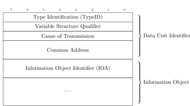
[image:33.612.92.476.112.326.2]Figure 2.6: Application Service Data Unit (ASDU) structure
Table 2.3: ASDU types defined in IEC 60870-5-104
TypeID
0..44 Process information in monitoring direction (from slave to master) 45..69 Process information in control direction (from master to slave) 70..99 System information in monitor direction
100..109 System information in control direction 110..119 Parameter in control direction
120..127 File transfer
Not every device that implements IEC-104 implements all of these different TypeIDs. As specified in the standard, every device should have an interoperability list, that specifies which ASDU types are supported, combined with which Causes of Transmission can be used for each type [42].
2.4.2 State transition diagram
2.4. IEC 60870-5-104 35 60870-5-104/FDIS © IEC – 21 –
STOPPED connection __________ start STARTED connection __________ Pending UNCONFIRMED STOPPED connection __________ U-frame[]/ or S-frame[]/ or I-frame[]/ U-frame[]/
S-frame [no unconfirmed I-frames] /Send STOPDT con
STOPDT act[unconfirmed I-frames]
U-frame[]/ or S-frame[]/ STARTDT act[]
/Send STARTDT con
stop Timeout t1[]/Active close
or S-frame[]/Active close or I-frame[]/Active close
Timeout t1[]/Active close
Timeout t1[]/Active close or I-frame[]/Active close STOPDT act[no unconfirmed I-frames]
/Send STOPDT con Connection established
Connection terminated
NOTE 1 Connection terminated means that there is no longer any data exchange betwen TCP and the application protocol (CS104).
[image:35.612.88.489.134.517.2]NOTE 2 t1 is the timeout of a sent U-frame or I-frame.
Figure 17 – State transition diagram for Start/Stop procedure (controlled station)
2.4.3 IEC-104 parameters
[image:36.612.117.512.226.380.2]In IEC-104 several parameters are used, that have to be defined for each device. The TCP port number should be 2404 in all cases. In Table 2.4 the other parameters are explained and their default values are given.
Table 2.4: IEC-104 parameters and default values [42]
k Maximum number of unacknowledged I-format APDUs before transmitter terminates
(default: 12 APDUs)
w Maximum number of received I-format APDUs before receiver must acknowledge
(default: 8 APDUs)
t0 Time-out of connection establishment (default: 30s) t1 Time-out of receiving response to latest sent
I-format/U-format APDUs
(default: 15s)
t2 Time-out for sending acknowledgement S-format
mes-sage (t2 < t1)
(default: 10s)
t3 Time-out for sending TESTFR after not receiving any
APDUs
(default: 20s)
2.5
Conclusion
37
Chapter 3
Representing protocols
This chapter starts in section 3.1 with an explanation regarding what is meant with the implementation of a protocol. Next, methods to formally describe protocols are given in section 3.2, after which in section 3.3 an elaboration is given on how automata, i.e. these formal descriptions, are learnt. In section 3.4 the algorithm to learn these automata is given. Section 3.5 gives a description on how to compare these automata with each other, after which section 3.6 this chapter concludes.
3.1
Protocol implementation
In short, an implementation is the interpretation of a specification that is presented in a standard for a particular protocol. When a specification is unclear, e.g., it consists only of a long ambiguous textual description [34], it might be interpreted differently then intended during the implementation of a protocol. This causes differences in interpretation of the specification which results in differences in the implementations of this specification.
For example, suppose a specification defines a protocol structure as shown in Figure 3.1 and specifies that: “If flag F is set in the packet, field X contains the value of parameter
. . . F
X Y
Figure 3.1: Example protocol
. . . 0
0 Y
(a)Field X is zero when F=0
. . . 0
undefined Y
(b)Field X is undefined when F=0
. . . 0
Y
(c) Field X is skipped when F=0
3.2. Formal protocol description 39
The implementation of a protocol should be able to handle every input in every state. If there are states in a protocol where some input cannot be handled, this could poten-tially result either in incompatibilities between different implementations or even worse, in security flaws [34]. In such a case, it might be possible to let an implementation crash by sending a specially crafted input when the implementation is in a certain state of the protocol. This could, e.g., be used in a denial of service attack. Van den Broek et al. show that this was possible in GSM [45]. By sending specially crafted messages, they were able to crash a mobile phone.
3.2
Formal protocol description
As described in the previous section, protocols describe which messages can be exchanged and which rules have to be followed. An implementation should be able to handle all of these messages in each state. Therefore, the messages of these protocols can be regarded as symbols in the alphabet of all possible messages.
Gunawan et al. describe three types of models to formally describe protocols: the State Transition Model, the Programming Language Model and the Hybrid Model [16]. State Transition Models describe protocols as a finite graph where the protocol’s events are described as inputs and outputs between nodes. Programming Language Models describe protocols in a high level programming language notation. Hybrid Models combine both State Transition Models and Programming Language Models to describe protocols.
State Transition Models are the simplest models and are best understandable for hu-mans. Therefore, this study elaborates on the most widely accepted State Transition Model: the finite state machine (FSM), which is also known as the finite automaton. Henceforward, this study refers to these FSMs using the term automaton.
Similarly, Verleg [46] discovered differences between different implementations of the SSH protocol. He discovered that in a situation where the standard does not specify what to do, different implementations act differently.
Generally, there are two different types of automata in the form of FSMs: i) those that either accept or reject an input and ii) those that return an output depending on the input. From the first type, deterministic finite automata are described in section 3.2.1. For the second type, Mealy machines are described in section 3.2.2.
3.2.1 Deterministic finite automaton
A simple automaton is the deterministic finite automaton (DFA). A DFA consists of states and actions [31]. By performing an action in a certain state, you are able to reach a new state. Furthermore, it has one starting state and one or more accepting states. In Figure 3.3 an example DFA is shown. The starting state of this DFA iss0 and the only accepting
state also is s0.
DFAs can be used to describe which sequences of actions are accepted and which are rejected. When a specific sequence of actions starting from the starting state transitions the DFA into an accepting state, that means that that sequence of actions is accepted. Otherwise, if the DFA is not in an accepting state after the sequence, that means that the sequence is rejected by the DFA.
s0
s1
s2
A B
B A
[image:40.612.196.457.411.561.2]A B
3.2. Formal protocol description 41
3.2.2 Mealy machines
To represent the implementations, the research by Verleg [46] is used as example on how to represent the automata in the form of Mealy machines. A Mealy machine is a com-prehensible automaton consisting of states and transitions. A combination of both the current state and the input determine the next state. Except for that, this combination also determines the output. This results in each transition containing both an input and an output.
In contrast to DFAs, Mealy machines do not only describe whether a sequence of inputs is accepted or rejected, but is also able to describe more of the behaviour of the system in terms of output.
s0
s1
s2
A/B B/B
B/B A/A
[image:41.612.151.425.285.443.2]A/B B/A
Figure 3.4: Mealy machine
In Figure 3.4 a Mealy machine is graphically represented. The circles represent the states and the arrows represent transitions. As explained each transition represents both an input and an output, therefore also the arrow represents these two in the form of
input/output. For example, if in Figure 3.4 in states0 the input A is received, the output
B is returned and the state becomess1.
3.2.3 Protocol inputs (alphabet)
within feasible boundaries.
The complexity of this alphabet is determined by the level of detail of the alphabet. Generally, the more extensive the alphabet is, the more complex the learnt automaton becomes.
3.3
Automata learning
[image:42.612.172.479.296.334.2]The method used to infer automata is similar to the approaches used by Caldwall et al. [6] and Verleg [46]. In these approaches the automaton learning process requires three components, as seen in Figure 3.5. These components are a learner, a teacher and an intermediate layer (or mapper). The explanation of these terms can be found below.
Figure 3.5: Automata learning setup
Learner tool that implements a learning algorithm.
Teacher subject under test (SUT), e.g., the implementation of a protocol, of which the automaton is learnt.
Mapper abstraction layer used to abstract from the specific content and reduce the so-called alphabet (explained in section 3.4) of all possible requests. This layer determines the level of abstraction and therefore of detail of the alphabet. The mapper is constructed using extra information from informal specifications or observing the behaviour of the SUT [2].
3.4. Algorithm 43
4 (Methodology) describes the tool that actually applies this algorithm and produces these automata.
3.4
Algorithm
As a learning algorithm to learn automata, Angluin’s L? algorithm [3] can be used. The original version of this L? algorithm produces DFAs by randomly sending different se-quences of inputs from the alphabet and then observing if these are accepted. If a specific input, that causes all subsequent inputs to change their accepting behaviour, is found, a state change is inferred. By repeating this procedure, a DFA is inferred.
However, this originalL? algorithm only produce DFAs that describe whether inputs are accepted or not. To be able to produce Mealy machines that can represent the more complex behaviour of input/output systems, the algorithm needs some adjustments. Shah-baz and Groz describe these adjustments and show how the L? algorithm can be altered to produce Mealy machines [37]. The result of this is the L?M algorithm (Algorithm 1).
Instead of observing whether an input is accepted, this alteredL?M algorithm observes the output that is returned for each input [8]. If, then, an input is found that causes all subsequent inputs to produce different outputs, the algorithm infers that a state change occurred. By repeating this procedure, not a hypothesis for a DFA, but a hypothesis for a Mealy machine is inferred.
Before looking in greater detail to the learning process in the L?M algorithm, some terminology is defined:
distinguishing sequence input sequence that produces different outputs for different
states
access sequence input sequence to reach a specific state from the initial state
counterexample input sequence that results in different outputs for the teacher and the hypothesis
When looking in greater detail to the L?M algorithm, the learning consists of first creating a hypothesis and then iteratively refining this hypothesis in a process that consists of two steps: the membership step and the equivalence step.
known state results in a transition to another known state, the model is closed. When every state has exactly one transition for every input, the model is consistent. When the model is both closed and consistent, a hypothesis is generated and this hypothesis is passed to the equivalence step.
In the equivalence step, the learner sends equivalence queries to the teacher to check if the the hypothesis is equal to the automaton of the teacher. If these are not equal it means that a counterexample is found. Then, the membership step is repeated with the coun-terexample used as an additional distinguishing sequence. When no more councoun-terexamples are found in the equivalence step, the hypothesis is returned as final and the learning has finished.
Algorithm 1 shows the pseudo-code of the complete L?M algorithm. Here, the Input Alphabet AI is the alphabet as described earlier. The Output Alphabet AO consists of all
possible outputs. The hypothesis is structured as the so-called Observation Table (OT). This OT can be represented as a 3-tuple (S, E, T), that consists of a set of prefixes (S), a set of suffixes (E) and a finite function (T) that maps combinations of prefixes and suffixes to an output.
The OT is called closed when adding any symbol of the alphabet has an equivalent output to one of the rows that already exists. TheOT is calledconsistent if for all prefixes that have the same output row, the outputs of that prefixes followed by the same letter of the alphabet and suffix are also the same.
3.4. Algorithm 45
Algorithm 1 L?M: learning algorithmL? for Mealy machines [3, 31, 37, 17] Input AlphabetAI
Output AlphabetAO
Observation TableOT = (S, E, T), where initiallyS ={} andE =AI
repeat
OT ←update(OT)
while (¬isClosed(OT)∨ ¬isConsistent(OT)) do
if ¬isClosed(OT) then .∃s1 ∈S, a∈AI.∀s∈S.row(s1·a)6=row(s) S ←S∪ {s1·a}
OT ←update(OT)
end if
if ¬isConsistent(OT) then .∃s1, s2 ∈ S, a ∈ AI, e ∈ E.row(s1) = row(s2)∧T(s1·a·e)6=T(s2·a·e) E ←E∪ {a·e}
OT ←update(OT)
end if end while
Mconj ←M(OT) .conjecture Mealy machine after the first phase of this round
σconj ←EO(Mconj) . EO denotes a call to the Equivalence Oracle if σconj 6=⊥ then
S←S∪P ref ix(σconj) . P ref ix(σ) generates the set of all
pos-sible prefixes of σ including σ itself
end if
untilσconj =⊥ .until no counterexample is found
functionupdate(OT)
for(s∈(S∪S·AI), e∈E)do
T(s·e)←M O(s·e) . M O denotes a call to the Membership Oracle
end for
return (S, E, T) . updatedOT
end function
functionM(OT)
Q← {row(s)|s∈S}
for(s∈S, a∈AI) do
δ(row(s), a)←row(s·a)
λ(row(s), a)←T(s·a)
end for q0 =row()
return (Q, AI, AO, δ, λ, q0) . Mealy machine
3.4.1 Example
As an example of how the algorithm runs, this section describes a scenario that shows how Mealy machines are generated. Given a SUT that holds a variable x and has an input alphabet a, b and an output alphabet 0,1. Initially this value x = 0. When the SUT receives an input athe value of x is XORed with 1 and the result is returned as output. When the SUT receives a b the current value of x is returned as output. For example, when first an ais sent, the SUT returns a 1. If the ais followed by a b this results in the SUT again returning a 1. When subsequently another ais sent, this now causes a 0 to be returned.
3.5. Automata comparison 47
E
a b
S 1 0
S·AI
a 0 1
b 1 0
x = 0
b / 0
a / 1
(a) First OT and Mealy machine
E
a b
S 1 0
a 0 1
S·AI
b 1 0
aa 1 0
ab 0 1
x = 0
b / 0
x = 1
a / 1 a / 0
b / 1
[image:47.612.351.461.125.431.2](b)FinalOT and Mealy machine
Figure 3.6: Observation Tables and automata learnt from Example
3.5
Automata comparison
When this methodology is used to formally describe multiple implementations as automata, it is possible to compare these automata. Moreover, it could be valuable to compare a derived automaton directly to the specification. To be able to compare an automaton to an automaton that is produced using L? or derived from the specification, a method of comparison is needed. Possible methods of comparison are described next.
easily be understood, as they are equivalent when the same sets of inputs lead to either an accepting state or not. For other automata, like Mealy machines, this means, that two automata with the same input and output alphabet, are equivalent if they produce the same output for each input, when starting from the same initial state. Therefore, it is possible to check if two automata are equivalent by traversing over both automata in parallel, while checking if the same input produces the same output. In order to show that two machines are not equivalent, a sequence of inputs needs to be found, such that this produces different outputs for the two machines. If such an output exists in some state, the automata are not equivalent. Otherwise, if such a difference cannot be found after traversing over the entire automaton, this means that the automata are equivalent.
Aarts et al. [1] describe an alternative method which uses conformance learning model-based testing. This is a method to compare two models that were learnt using automata learning. In this method they use the CADP (Construction and Analysis of Distributed Processes) toolset, which is a toolset that can check the equivalence of two Mealy machines. Another possibility for the comparison of an automaton to a specification, is by using Holzmann’s SPIN [18]. SPIN is an automatic model checker that is able to automatically check an automaton against a specification when that specification is modelled using SPIN. Also, the inferred automata can be compared with existing automata that originate from the specification. For example, F. Qin-cui et al. describe how to model the protocol specification of IEC-104 as an automaton [15].
3.6
Conclusion
49
Chapter 4
Methodology
The following chapter describes the design of the set-up. Beside the earlier described teacher, learner and mapper that are part of the set-up, this chapter introduces a fourth component to the set-up: the checker. The set-up with these four components is graphically shown in Figure 4.1 and is described in section 4.1, after which the separate components are described in depth in sections 4.2 to 4.5.
4.1
Set-up
The learner implements theL?M algorithm as described in section 3.4. As shown in Figure 4.1, the learner consists of several components: (i) the experiment, (ii) the membership oracle + cache and (iii) the equivalence oracle. The experiment uses the membership oracle to learn a hypothesis (which is structured as an Observation Table). During learning the membership oracle sends abstract membership queries to the mapper (as presented in Figure 4.1 as steps 2 and 3), from which it in return receives abstract membership answers (steps 8 and 9). These queries and answers are called abstract because they are human readable and they make up the input and output alphabet of the Mealy machine. There is a cache between the membership oracle and the mapper, which stores each membership query and its corresponding answer. When a query is passed to this cache it will first attempt to look it up. Only if the answer is not found in the cache, it will be passed to the mapper. The membership oracle will continue sending queries until it has a closed and consistent Observation Table. Then a hypothesis Mealy machine is produced from the Observation Table.
SUT MembershipOracle EquivalenceOracle Cache Mapper Experiment Alphabet IEC-104 Master IEC-104 Slave 1 10 2 9 3 8 12 17 18 11 5, 14 6, 15 4 7 13 16
Learner Mapper Teacher 1 : Learn / Refine Hypothesis
2, 3 : Abstract Membership Query 4, 5 : Concrete Membership Query 6, 7 : Concrete Membership Answer 8, 9 : Abstract Membership Answer 10,11 : Hypothesis
12 : Abstract Equivalence Query 13,14 : Concrete Equivalence Query 15,16 : Concrete Equivalence Answer 17 : Abstract Equivalence Answer 18 : Confirmation / Counterexample 19 : Final Hypothesis
Checker
[image:50.612.122.525.242.498.2]19
4.2. Learner 51
and then starts to send 1000 random queries to the mapper, while checking if it matches the hypothesis. While sending these queries, there is a 1% change that the SUT and the hypothesis are reset to the initial starting position. When one of these queries contradicts with the hypothesis, this query is called a counterexample. If no counterexample is found after the 1000 random queries, the hypothesis is confirmed.
As described, the learner sends queries to the mapper. The main goal of the mapper is to transform the human readable abstract queries to concrete queries that comply to the protocol. Conversely, it also transforms the concrete answers back into more simple and human understandable abstract answers that can be used in the Mealy machine.
The teacher is the SUT, which is an implementation of an IEC-104 controlled station (slave). To manage the connection with this slave and to really send the messages to it, the mapper sends its messages to an IEC-104 controlling station (master) that was implemented. This master then takes these messages, sends them to the SUT and waits for the SUT to respond. If the SUT does not respond within a specified interval, the master returns to the mapper that there was no answer. This interval can be configured.
Finally, the final hypothesis is compared to the standard by the checker. In order to do this, the set-up contains a automaton for the standard, with which the produced automaton is compared.
4.2
Learner
To learn the automata of the IEC-104 implementations a framework named LearnLib [27] was used. This framework was used to implement both the learner and the mapper as described in the previous section. In the following section this framework is described in more depth.
4.2.1 LearnLib
LearnLib is a Java library that contains a framework to implement both the classical L?
4.2.2 Design of the Alphabet
[image:52.612.109.547.238.432.2]The alphabet is chosen so that it implements all the different message format types from the IEC-104 standard as described in section 2.4. Of these, all three different U-format types are part of the alphabet and for all of the different categories of I-format messages there is one in the alphabet. The complete alphabet is shown in Table 4.1.
Table 4.1: Alphabet
Word Representation
U[STARTDT]
U-format message for starting or stopping data transfer or for testing the connection, as described in section 2.4
U[STOPDT] U[TESTFR]
S S-format message as described in section 2.4
I[0] Artificial I-format message with undefined TypeID 0 I[C SC NA]
All specified I-format ASDU command types are in the alphabet. A complete list of these can be found in Appendix A
I[C DC NA] ..
.
I[F DR TA] I[F SC NB]
Lmax Artificial message that only contains the START byte (104) and the
length field set to the maximum om 253 without actually containing that length
Because of the limitations for learning within feasible boundaries as described in section 3.2.3, not the entire alphabet is used in every run, but a sub-alphabet is constructed out of this alphabet. Automata are created with these sub-alphabets.
Every I-format messages uses a Cause of Transmission that is allowed according to the definition in the standard. When it is allowed, this Cause of Transmission is Activation. Otherwise, it is the most common Cause of Transmission for that TypeID.
4.3
Mapper
4.3. Mapper 53
concrete message. These concrete messages are structured according to the formats as defined in the IEC-104 specification (except for the abstract messages I[0] and Lmax). For
example, the abstract message I[C SC NA] is translated to a concrete message that is shown in Figure 4.2. In this Figure the I-format APCI header from Figure 2.5c and the ASDU from Figure 2.6 are combined to form the I[C SC NA] APDU. To implement these concrete messages OpenMUC j60870 [32] is used.
[image:53.612.102.450.218.497.2]0 1 2 3 4 5 6 7 104 START 14 Length 0
[1 - 65535]
)
Send Sequence Number
0
[1 - 65535]
)
Receive Sequence Number
C SC NA (45) Type Identification
0 1 Variable Structure Qualifier
0 0 Activation (6) Cause of Transmission
[configurable]
)
Common Address
0
)
Information Object Identifier (IOA)
0 0 0 1 Single Command
Figure 4.2: Example of concrete mapping from I[C SC NA]
4.4
Teacher
To communicate with the SUTs, which are 104 controlled stations (slaves), an IEC-104 controlling station (master) was implemented using OpenMUC j60870 [32]. However, before j60870 could be used for this research, several additions and modifications had to be made. OpenMUC j60870 already implements large parts of the protocol, however, as it was necessary to be able to control all fields inside the APDUs, several parts needed to be rewritten. The connection handler needed to be adapted to be able to have control over the APDUs. Furthermore, j60870 did not support sending and receiving of STOPDT and TESTFR messages, so these had to be implemented as well.
Also, all the different types of ASDUs needed to be implemented, as well as the custom ASDU with TypeId 0 (I[0]) and the custom APDU with the length set to the maximum of 253 (Lmax). For the implementation of these, parts of j60870 were used.
In the implementation of this tool the default parameters for IEC-104 were used as described in section 2.4.
4.4.1 Subjects under Test
The SUTs are the slave implementations of IEC-104. All of these implementations used the default parameters for IEC-104 as defined in Table 2.4. For this research, it was possible to acquire access to five different implementations, of which three are simulators and two are real devices. These implementations are the following:
Axon Test Simulation tool from Axon Group for both masters and slaves of DNP3,
IEC-101, IEC-104 and Modbus [4]. From this tool only the IEC-104 slave was used. This simulation tool was obtained from http://www.axongroup.com.co/axongroupen/axon_
productos_int.php?i=36.
IEC 870-5-104 Simulator Simulation tool from Mitra Software that simulates an
IEC-104 slave [29]. This simulation tool was obtained from http://mitraware.com/apps/
iec104sim.php.
4.4. Teacher 55
Figure 4.3: Test Set-up at Stedin
Sprecher Sprecon-E-C-92 Implementation of an RTU in a real device. Functions as
Figure 4.4: Test Set-up Datawatt
Datawatt D05-Lite Implementation of an RTU in a real device. Can be used as a fully
functional PLC with support for several ICS protocols, e.g., Modbus and IEC 60870-5-101, -103 and -104. This device was used as an IEC-104 controlled station. Figure 4.4 shows the test set-up of this device. Access to this device was provided by Cogas.
4.5
Checker
4.5. Checker 57
the UNCONFIRMED STARTED state is the state in which there are unconfirmed I-frames. The other states are the same as in the state transition diagram, where TERMINATED is the state in which the connection is terminated.
STOPPED U[STOPDT] / U[STOPDT]U[TESTFR] / U[TESTFR]
STARTED
U[STARTDT] / U[STARTDT]
TERMINATED
S / ERROR I / ERROR U[STOPDT] / U[STOPDT]
U[STARTDT] / U[STARTDT] U[TESTFR] / U[TESTFR]
S /
-UNCONFIRMED STARTED
I / I
U[STARTDT] / ERROR U[STOPDT] / ERROR U[TESTFR] / ERROR
S / ERROR I / ERROR S /
-U[STARTDT] / -U[STARTDT] U[TESTFR] / U[TESTFR]
I / I
UNCONFIRMED STOPPED U[STOPDT] /
-S / U[-STOPDT]
I / ERROR
[image:57.612.74.501.185.524.2]U[STARTDT] / U[STOPDT] / -U[TESTFR] / -U[TESTFR]
Figure 4.5: Automaton deduced from IEC-104 State Transition Diagram (Figure 2.7)
automata as described in section 3.5. The algorithm that is implemented in the checker is shown in Figure 2.
Algorithm 2 Checker algorithm for checking Mealy machine equivalence
Mealy machines (Q, AI, AO, δ, λ, q0) and (Q0, AI, AO, δ0, λ0, q00)
P ← {(q0, q00)} .queue of state tuples to process
repeat
(q, q0)←head(P) . take first tuple from process queue
for a∈AI do . for every word in the alphabet
if λ(q, a)6=λ(q0, a) then . if the outputs are different
d←wordsT oReach(q)∪a .separating word is found
end if
if (δ(q, a), δ0(q0, a))∈/R then .if successor state is not already processed
P ←P ∪(δ(q, a), δ0(q0, a))) . add successor states to process queue
end if end for
P ←tail(P) . remove processed tuple from process queue
R←(q, q0) .add processed tuple to set of processed state tuples
untilP =∅ . until all reachable combinations of states are processed
return(d==⊥) . return whether no separating word is found
4.6
Conclusion
59
Chapter 5
Results
The results are presented in the following chapter. First, in section 5.1, the results col-lected from the three simulators (Axon Test, Mitra Software IEC 870-5-104 Simulator and Siemens IEC-Test) are discussed. Next, in section 5.2, the results collected from real implementations (Datawatt and Sprecher) are examined.
As shown next, in most automata only one ASDU type is used for I-format messages. This is the case because differing the I-format ASDU type would not lead to a different automaton. Also, for certain ASDU types this would lead to differences that are only based on the amount of information objects returned per message. This would only lead to larger automata that actually are equivalent to those presented here.
5.1
Simulators
STARTED
U[STARTDT] / U[STARTDT] | I[M_EI] U[STOPDT] / U[STOPDT]
U[TESTFR] / U[TESTFR] S /
[image:60.612.220.432.152.257.2]-I[C_SC] / -I[C_SC]
Figure 5.1: Automaton learnt from Axon Test simulator
5.1.1 Axon Test
The first tested simulator was the Axon Test simulator mentioned in section 4.4.1. As can be seen in Figure 5.1, Axon Test responds with a confirmation message when it receives any message. This shows that Axon Test only simulates responses on the IEC-101 layer. It only confirms the U-format messages of the IEC-104, but further ignores them. Therefore only a single state exists that is most similar to the STARTED state in the state transition diagram in Figure 2.7. Also, it can be seen that when Axon Test receives a STARTDT message it does not only reply with the STARTDT confirmation, but also with an End of
Initialization I-format message. This message is sent because Axon Test was reset before
every run. Although this simulator does not give an automaton that provides many new insights for comparison, it was useful to use it in the test phase in order to learn how the packages have to be structured, because it was crashed when it received a wrongly structured IEC-104 packet.
Limitations and challenges The IEC-104 standard was not implemented properly in
5.1. Simulators 61
STOPPED
U[STOPDT] / U[STOPDT] U[TESTFR] / U[TESTFR]
S / I[C_SC] /
-STARTED
U[STARTDT] / U[STARTDT]
U[STARTDT] / U[STARTDT] U[STOPDT] / U[STOPDT]
U[TESTFR] / U[TESTFR] S /
[image:61.612.186.391.169.354.2]-I[C_SC] / -I[C_SC]
Figure 5.2: Automaton learnt from Mitra Software IEC 870-5-104 Simu-lator
5.1.2 Mitra Software IEC 870-5-104 Simulator
Mitra Software’s IEC 870-5-104 Simulator is the only tested simulator that actually has more than one state. In its initial state the simulator only responds to U-format messages, but ignores I-format messages. Only when a STARTDT is sent, the simulator converts to a state in which it responds to I-format messages. However, once the simulator has reached this (STARTED) state, it cannot return to the initial (STOPPED) state when a STOPDT is sent. So after reaching the STARTED state, the simulator remains in this state as long is the connection is not reset. The learnt automata of this simulator can be seen in Figure 5.2.
Limitations and challenges The entire IEC-104 stopping process did not seem to be
STOPPED
U[STARTDT] / U[STARTDT] U[STOPDT] / U[STOPDT]
U[TESTFR] / U[TESTFR] S /
I[C_SC] /
-Figure 5.3: Automata learnt from IEC-Test Simulator
5.1.3 Siemens IEC-Test
The automaton that was learnt from IEC-Test (Figure 5.3) looks very similar to the au-tomaton of Axon Test. In its initial state IEC-Test responds to U-format messages, how-ever, it does not reply to any sent I-messages.
Limitations and challenges IEC-Test is a very manual tool that did not appear to
[image:62.612.224.427.175.274.2]5.2. Real devices 63
5.2
Real devices
STOPPED U[STOPDT] / U[STOPDT]U[TESTFR] / U[TESTFR]
STARTED
U[STARTDT] / U[STARTDT]
TERMINATED
S / ERROR I[P_ME] / ERROR U[STOPDT] / U[STOPDT]
U[STARTDT] / U[STARTDT] U[TESTFR] / U[TESTFR]
S /
-UNCONFIRMED STARTED I[P_ME] / I[P_ME]
U[STARTDT] / ERROR U[STOPDT] / ERROR U[TESTFR] / ERROR
S / ERROR I[P_ME] / ERROR S /
-U[STARTDT] / -U[STARTDT] U[TESTFR] / U[TESTFR]
I[P_ME] / I[P_ME]
UNCONFIRMED STOPPED U[STOPDT] /
-S / U[-STOPDT]
I[P_ME] / ERROR U[STARTDT] /
[image:63.612.73.504.130.509.2]U[STOPDT] / -U[TESTFR] / -U[TESTFR]
Figure 5.4: Automaton learnt from Datawatt implementation
5.2.1 Datawatt D05-Lite
state, the only messages to which the RTU responds are the TESTFR and the S-format confirmation message. Also a TERMINATED state is reached when specific unexpected messages are sent in a state, which also follows from the standard.
When looking at more different ASDU types, an automaton was found that does not comply to the standard when sending the, rarely used, I-format message for File Select. Then a new strange state appears, as can be seen in Figure 5.5. As the File Select message that is sent does not contain a valid address of a file, the RTU appears to be more strict than the standard by terminating the connection on the next received I-format message. However, according to the standard, the expected response would be a negative confirma-tion I-format message.
STOPPED U[STOPDT] / U[STOPDT]
STARTED U[STARTDT] / U[STARTDT]
TERMINATED S / ERROR
I[F_SC_NA] / ERROR I[F_LS_NA] / ERROR
U[STOPDT] / U[STOPDT]
U[STARTDT] / U[STARTDT] S /
-X
I[F_SC_NA] / -UNCONFIRMED
STARTED
I[F_LS_NA] / I[F_LS_NA] U[STOPDT] / U[STOPDT]
U[STARTDT] / U[STARTDT] S /
-I[F_SC_NA] / ERROR I[F_LS_NA] / ERROR
U[STARTDT] / ERROR U[STOPDT] / ERROR
S / ERROR I[F_SC_NA] / ERROR I[F_LS_NA] / ERROR
S /
I[F_SC_NA] /
-U[STARTDT] / -U[STARTDT] I[F_LS_NA] / I[F_LS_NA]
UNCONFIRMED STOPPED U[STOPDT] /
-S / U[-STOPDT]
I[F_SC_NA] / ERROR I[F_LS_NA] / ERROR
U[STARTDT] / U[STOPDT] /
[image:64.612.127.516.304.569.2]5.2. Real devices 65
STOPPED
U[STOPDT] / U[STOPDT] U[TESTFR] / U[TESTFR]
S / I[P_ME] /
-STARTED
U[STARTDT] / U[STARTDT] U[STOPDT] / U[STOPDT] U[STARTDT] / U[STARTDT]
U[TESTFR] / U[TESTFR] S /
-UNCONFIRMED STARTED I[P_ME] / I[P_ME] S /
-U[STARTDT] / -U[STARTDT] | I[P_ME] U[TESTFR] / U[TESTFR]
I[P_ME] / I[P_ME]
UNCONFIRMED STOPPED
U[STOPDT] / -S / U[-STOPDT]
U[STOPDT] / -U[TESTFR] / -U[TESTFR]
UNCONFIRMED STOPPED*
U[STARTDT] / U[STARTDT]
STOPPED* I[P_ME] / U[STOPDT] U[STARTDT] / U[STARTDT]
U[STOPDT] / -U[TESTFR] / -U[TESTFR]
S / U[STOPDT]
STOPPED* I[P_ME] / U[STOPDT]
U[STARTDT] / U[STARTDT] | I[P_ME]
U[TESTFR] / U[TESTFR] S / I[P_ME] /
-STOPPED* U[STOPDT] / U[STOPDT] U[STARTDT] / U[STARTDT] | I[P_ME] | I[P_ME]
U[TESTFR] / U[TESTFR] S / I[P_ME] /
-STOPPED* U[STOPDT] / U[STOPDT]
U[STARTDT] / U[STARTDT] | S | I[P_ME]
U[STOPDT] / U[STOPDT] U[TESTFR] / U[TESTFR]
S / I[P_ME] /
-U[STARTDT] / -U[STARTDT] | S | I[P_ME] | I[P_ME]
U[STOPDT] / U[STOPDT] U[TESTFR] / U[TESTFR]
S / I[P_ME] /
-Figure 5.6: Automaton learnt from Sprecher implementation
5.2.2 Sprecher Sprecon-E-C-92
[image:65.612.72.502.82.392.2]the Sprecher RTU to never terminate the connection when faulty packages are received, might be because it is used as a gateway to another IEC 61850 subnetwork.
Also, when the RTU is in the UNCONFIRMED STOPPED state, it is still possible to send a U-format STARTDT, which makes the RTU come in a sort of hybrid state between UNCONFIRMED STOPPED and STARTED.
5.3
Additional considerations
As described in section 4.2.2 two artificial messages, I[0] andLmax, were also implemented
in the developed tool. The I[0] messages did not provide any behaviour that was different from the normal behaviour. However, the tests with the Lmax message, consisting of only
the START byte (104) and the maximum length (253), provided some interesting results that are discussed here separately. When anLmaxmessage was sent in any state, the tested
implementations did not respond until they had received the total number of bytes that were specified in the length field. This means that every message that is sent after anLmax
message, is ignored, because the implementation thinks that message belongs to the initial
Lmax message. As showed in section 2.3.1, availability is of a great importance for ICS.
When messages are ignored, this is a problem for the availability of the system. Therefore, an attacker would be able to disrupt the communication by sending an Lmax message.
Furthermore, there are some rare occurrences where the algorithm gives some strange extra states during learning, while these in reality are not new states. These could be caused by interruption during learning. However, these automata are equal to each other. The checker properly handles these automata, because the comparison in the checker is based on the output sequences.
5.4
Conclusion
5.4. Conclusion 67
that is being closed. All simulators that were used, were very limited and therefore also do not comply to the specification.
[image:67.612.82.497.370.483.2]When comparing only the real devices to each other and the standard, there are two main differences that should be noted. The first one is the difference in whether the device terminates the connection, when it receives a message that is not allowed in that state. According to the standard, this termination of the connection should happen. The Datawatt RTU correctly terminates in these cases, while the Sprecher RTU ignores the message. The second difference is the behaviour when a STARTDT is received in the UNCONFIRMED STOPPED state. The standard specifies that this STARTDT should not cause a state change. However, the standard does not unambiguously specify if the device should respond to this STARTDT message. The Datawatt RTU correctly ignores this STARTDT and also does not respond to this. However, the Sprecher RTU shows some strange behaviour at this point. Not only does the Sprecher RTU respond to the STARTDT with a STARTDT confirmation (which is underspecified), but also a change in state occurs, which results in strange behaviour in its subsequent responses.
Table 5.1: Results overview
Implementation #states Standard
compliance
Started state
Terminated state
Standard 5 True True True
Axon Test 1 False False False
IEC 870-5-104 Simulator 2 False True False
IEC-Test 1 False False False
Datawatt D05-Lite 5 True True True
![Figure 2.1: Generations in development of ICS/SCADA [12]](https://thumb-us.123doks.com/thumbv2/123dok_us/9738480.474754/22.612.118.527.166.563/figure-generations-in-development-of-ics-scada.webp)
![Figure 2.4: Architecture of IEC TC57 Information Exchange Standards[10]](https://thumb-us.123doks.com/thumbv2/123dok_us/9738480.474754/29.612.139.436.231.488/figure-architecture-iec-tc-information-exchange-standards.webp)

![Table 2.4: IEC-104 parameters and default values [42]](https://thumb-us.123doks.com/thumbv2/123dok_us/9738480.474754/36.612.117.512.226.380/table-iec-parameters-and-default-values.webp)
