http://wrap.warwick.ac.uk/
Original citation:
Papaefstathiou, E., Kerbyson, D. J., Nudd, G. R. and Atherton, T. J. (1995) An
introduction to the CHIP3S language for characterising parallel systems in performance studies. University of Warwick. Department of Computer Science. (Department of Computer Science Research Report). (Unpublished) CS-RR-280
Permanent WRAP url:
http://wrap.warwick.ac.uk/60965
Copyright and reuse:
The Warwick Research Archive Portal (WRAP) makes this work by researchers of the University of Warwick available open access under the following conditions. Copyright © and all moral rights to the version of the paper presented here belong to the individual author(s) and/or other copyright owners. To the extent reasonable and practicable the material made available in WRAP has been checked for eligibility before being made available.
Copies of full items can be used for personal research or study, educational, or not-for-profit purposes without prior permission or charge. Provided that the authors, title and full bibliographic details are credited, a hyperlink and/or URL is given for the original metadata page and the content is not changed in any way.
A note on versions:
for Characterising Parallel Systems
in Performance Studies
†E. Papaefstathiou, D.J. Kerbyson, G.R. Nudd, T.J. Atherton
Parallel Systems Group Department of Computer Science
University of Warwick
Abstract
A characterisation toolset, Characterisation Instrumentation for Performance Prediction of Parallel Systems (CHIP3S), for predicting the performance of parallel
systems is presented in this report. In this toolset expert knowledge about the performance evaluation techniques is not required as a prerequisite for the user. Instead a declarative approach to the performance study is taken by describing the application in a way that is both intuitive to the user, but can also be used to obtain performance results. The underlying performance related characterisation models and their evaluation processes are hidden from the user. This document describes the special purpose language, and the evaluation system, that form the core of the CHIP3S toolset.
Amongst the aims of the toolset is the support of characterisation model reusability, ease of experimentation, provide different levels of prediction accuracy, and support of different levels of characterisation model abstraction.
1. Introduction
Performance evaluation is an active area of interest especially within the parallel systems community. A large number of performance tools have been developed to assist the system developer, the application programmer, and the tuning expert to select the most efficient combination of hardware and parallelisation strategy [Miller90, Parashar93, Pease91, Reed92]. However, the use of performance tools typically require an advance knowledge of performance related issues, which is usually not commonly understood. The purpose of the characterisation work at Warwick is the development of prediction, and analysis of, methodologies and tools that will allow non performance specialists to undertake performance studies. CHIP3S
(Characterisation Instrumentation for Performance Prediction of Parallel Systems) is a set of tools aimed to assist the users to undertake performance studies. In this document a special purpose language and an evaluation system is presented that form the core of the CHIP3S performance toolset.
The notion of performance tools for the "rest of us" is the central driving force behind Warwick's characterisation work. In order to achieve this goal, the user of the performance methodology must focus his/her effort on the aspects of the performance study that does not require performance related speciality. The user of performance tools usually knows the application but does not have any knowledge of the performance methodologies. The characterisation toolset presented here requires the user to describe the application that is under investigation in a way that is both intuitive to the user but can also be used in the performance study. The performance related characterisations and their evaluation process, are hidden from the user.
The characterisation methodology provides the following features:
• Characterisation Model Reusability: Allows the definition of the control flow of the application and the computation/communication pattern in a hardware independent way.
• Easy Experimentation: Allows easy experimentation with different hardware platforms and parallelisation strategies.
• Different Levels of Prediction Accuracy: Supports different levels of characterisation from high level parametric characterisation (e.g. measuring floating point operations), providing moderate accuracy, to low level instruction level characterisation, providing high accuracy of predictions.
• Different Levels of Model Abstraction: Can be used in different stages of software development cycle and different type of software development projects (e.g. serial code porting, parallel software developed from scratch).
The CHIP3S toolset is based on a characterisation framework [Nudd93,
Papaefstathiou93, Papaefstathiou94a, Zemerly94]. This framework is a layered approach that separates out the hardware and software systems through the use of a parallelisation template, Figure 1. This modular approach leads to readily re-usable models which can be interchanged in experimentation. For instance the performance predictions across parallelisation techniques can be compared for a particular application on a particular hardware. The layers used are detailed below:
• an application layer, which describes the application in terms of a sequence of sub-tasks using control flow graphs. Each node of the graph can be a sequential processing node, a user defined parallel sub-task, or a parallel processing generic (from a library).
• an application task layer, which describes the sequential part of every sub-task within an application that can be executed in parallel. The result of the evaluation of these models is fed to the parallel template layer.
• a parallelisation template layer, that describes the computation-communication pattern and other hardware resource usage.
Application Layer
Sub-Task Layer
Parallelisation Templates
Hardware Layer
Application Domain
Figure 1 - The Layered Characterisation Framework
• a hardware layer, which is responsible for characterising the communication and computation abilities of the system.
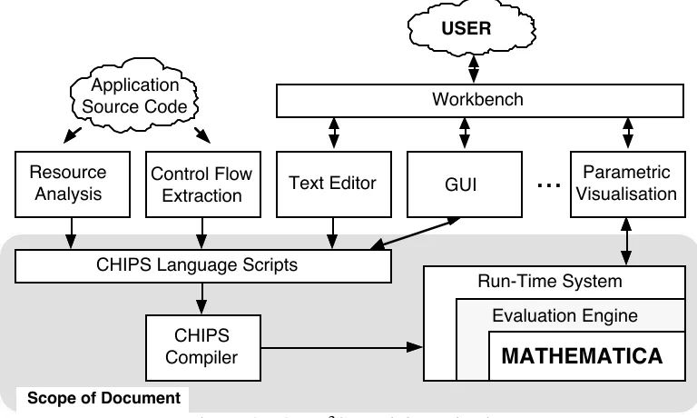
The CHIP3S toolset contains a number of
separate programs integrated under a common graphical user interface. The organisation of these components is shown in Figure 2. The main components of this toolset are:
• A set of special purpose language scripts suitable for the description of performance aspects of parallel systems.
• A run-time system that contains an evaluation engine (Mathematica)
• A set of interface tools which allow the extraction of control flow/resource information from application source code.
• A further set of graphical interface tools that allow the user to define aspects of the performance study and visualise the outputs.
The CHIP3S run-time system is responsible to perform basic maintenance operations
such as the loading of CHIP3S compiler output, the evaluation of models, and the
storage of the results. The run-time system also includes the evaluation engine that is used to combine and evaluate the models of the performance study. The user will be able to examine the results through a visualisation module and experiment with the performance parameters. A number of pre-defined number of performance analysis studies will be provided such as scalability and bottleneck analysis.
An automated procedure is provided to extract from the user's application the control flow and resource requirements from the user's application. Additionally the resource usage of each node of the control flow graphs is identified in terms of a high level language, or instruction level operations. The resource usage information is combined with the control flow information and converted to CHIP3S language scripts.
The user will be able to edit his/her own CHIP3S language scripts and use the
Graphical User Interface (GUI) module to design the computation/communication pattern of the parallel algorithm used, and the control flow of an application that has not yet been developed. After the development of CHIP3S scripts have been concluded
for a performance study the CHIP3S compiler will translate the scripts to Mathematica
source code.
Resource Analysis
Control Flow
Extraction Text Editor GUI
Parametric Visualisation
...
Application Source Code
USER
CHIPS Language Scripts
CHIPS
Compiler MATHEMATICA
Evaluation Engine Run-Time System
Scope of Document
[image:4.595.130.514.406.636.2]Workbench
Figure 2 - CHIP3S Tool Organisation
The scope of this document is to present the CHIP3S language, the Mathematica
run-time system, and the evaluation engine.
In the next section the main entities (objects) of the CHIP3S language are introduced.
There are four types of CHIP3S objects (related to the layered framework): the
language description is presented. The language is presented in BNF format and the semantics of it's constructs are explained. In Section 5 an example is given for predicting the performance of a parallel sorting kernel. Finally in Section 6 a summary and a number of extensions that will be included in future versions of the language are described.
2. Objects and Object Interfacing
A program written in the CHIP3S language includes a number of objects. Each object
is one of the following types: application, subtask, parallel template, and hardware. These are used to describe the performance aspects of the respective system components. An object is comprised of:
• Internal Structure: The internal structure is defined by the programmer and is hidden from the other objects. This structure contains various types of procedures that describe the control flow of the application, the form of any regression models, and computation-communication structures.
• Options: The objects, depending on their type, have a number of pre-defined options that determine the default behaviour of the object. The default values of these options can be set in the object, and can be modified by other objects. For example an option might include the default hardware or parallelisation strategy (parallel template) that will be called by a subtask.
• Interface: Objects include an interface that can be used by other objects to modify their behaviour. This interface is explicitly defined by the programmer. The interface includes the external variables that can be modified outside of the object scope. The interface might include data dependent, hardware dependent, and other variable types.
Template Subtask
Hardware Template Subtask Application
Hardware Template Application
Hardware Subtask Application
User User User
Application Object Interface
Subtask Object Interface
Template Object Interface
Write
Read
Interface Operations
w
w
r / w
r / w r
w
r / w
r
w
r
r
Figure 3 - Object Interfacing
Objects of a certain type can only read from, and write to, certain other object types as shown in Figure 3. An object can read an external variable of other objects only if it is in a lower level of the layered approach hierarchy. Further rules that govern this relationship are described below:
• Application Type Object: A CHIP3S program includes only one object of the
The external interface of the application object can be used by the user, through the CHIP3S run-time system, to manipulate parameters of the performance study (e.g.
change the size of the problem). The application object can modify the external variables of subtask and hardware objects and also use entire subtask objects. For example, a parallel sort application object can use constituent quicksort and bitonic sort subtask objects but only modify the processor configuration of the underlying hardware platform, without directly calling it.
• Subtask Type Object: A CHIP3S program might include many subtasks. The
interface of a subtask object can be modified by the application object. A subtask can modify the external variables and use template objects. For example the bitonic sort is an object of the subtask type that can be used by the application object, it can modify the external variables and use the bitonic parallel template object.
• Parallel Template Type Object: A program might include many parallel template objects. Their interface can be manipulated by subtask objects. The parallel template can not modify the interface of any other object type. The parallel template object describes the computation-communication patterns and the use of other hardware resources.
The definition of hardware objects is not supported directly by the CHIP3S language.
The hardware objects must be developed using Mathematica and other analytical or simulation tools. The characteristics and the parameters of a hardware object must be defined in a hardware symbol file. This file is included into the user-defined objects that use hardware parameters.
The CHIP3S environment provides some special purpose objects that have extended
semantic features. These include a template with the name sequential that covers the case of the execution of a subtask on a single CPU. Also a object called hardware will contain a common interface of all hardware platform parameters (e.g. number of processors). This will allow the reference to the hardware objects independently of the type of the parallel system in use. Finally a special case is the symbol file the object la, that contains parameters related to the status of the CHIP3S run-time system and
evaluation engine. An object by including the la symbol file can query the status of CHIP3S.
For each object type a detailed description is given in the following sub-sections below:
2.1 Application Object
A CHIP3S program contains one application object. The object acts as the entry point
of the performance study, and includes an interface that can be used by the user through the CHIP3S run-time system to modify parameters of the performance study
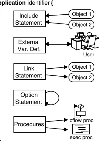
(e.g. data dependent parameters, hardware platforms to be used). Additionally the application object combines the subtask objects using either control flow graphs or execution procedures. An application object includes the following parts (Figure 4):
• IncludeּStatement: Declares the subtask, parallel template, and hardware objects that will be used by the application object.
• External Variable Definition: Defines the external variables that will be the interface between the application object and the user through the CHIP3S run-time
• Linking Statement: The purpose of the link statement is to modify external variables and options of the subtask objects and the hardware objects being used.
• Option: Sets the default options of the application object. These options can be also modified by the user through the CHIP3S run-time system.
• Procedures: The procedures describe the relationships of the subtasks in order to predict the performance of any serial parts of the application. This relationship can either be described as control flow graphs (cflow) or execution statements (exec). Control flow graphs are defined in terms of graph components, where as execution statements are more flexible allowing complex relationships to be expressed. The application object must include an execution procedure named init.. This procedure is the entry point of the program.
Include Statement applicationidentifier{
Object 1
Object 2
Link Statement
Object 1
Object 2 External
Var. Def.
User
Option Statement
Procedures
}
cflow proc
[image:7.595.124.293.244.503.2]exec proc
Figure 4 - Application Object Structure
2.2 Subtask Objects
The subtask objects represent parts of an application that are parallelised on a hardware platform using a specific parallelisation strategy. The subtask objects in an application are combined by the single application object.
A subtask object includes the evaluation of the sequential parts of the parallel program. It also includes the mapping of these sequential parts of the application onto the computation-communication pattern described in the parallel template object.
A subtask object can use more than one parallel template object in the case when a part of the application uses more than one parallelisation strategies. This features gives the flexibility for easy experimentation and selection of the appropriate parallelisation strategy for a hardware platform. During an execution of a CHIP3S program only one
template might be evaluated for each subtask.
The subtask object has the same structure as the application object (as shown in Figure 4). The role of the init procedure in a subtask object is to specify the execution time of the serial part of the subtask when linked into the parallel template. The presence of the init function is optional in the subtask objects. An init function might not be required when the serial parts of the subtask are constant and can be specified directly in the link statement.
Application Obj
Proc1
Init Map
Proc n
...
Subtask Obj
ParTmp Obj 1
ParTmp Obj 2
Execution Time
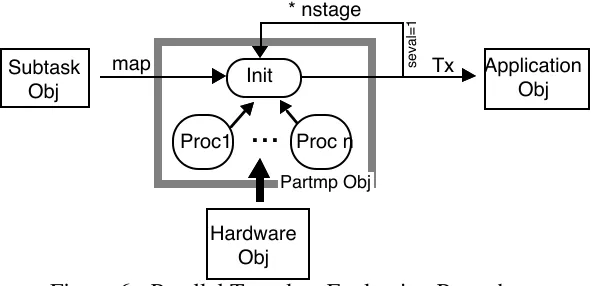
[image:7.595.181.466.634.727.2]Figure 5 shows the sequence of steps performed during the evaluation of the subtask object. The application object initially uses a subtask object. The init procedure of the object is the entry point. The init procedure might call other procedures of the object to evaluate the serial parts of the application. These parameters are linked to the currently active parallel template object that was specified by the option command in the subtask object or in the application object. Finally, the current parallel template object is called and evaluated. The results of the parallel template object evaluation is the execution time of the subtasks which is returned to the application object.
2.3 Parallel Template Objects
The parallel template object describes the computation-communication pattern and allows access to the hardware devices of a system. The syntax of the parallel template objects is similar to the application and subtask objects with the exception of the statement link and the existence of additional statements for exec procedures.
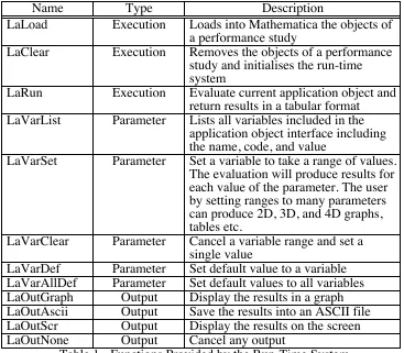
The parallel template objects do not manipulate the interface of any of the other objects so there is no need for the existence of the link statement. The computation-communication pattern is expressed in terms of stages and steps. A stage is a complete phase of the parallel algorithm and might include many computations and communications. In many cases a parallel template might have many stages of the same computation-communication pattern. In this case there is no need for the re-evaluation of the object for every stage. The number of stages in a parallel template object is defined with the option nstage. The method for evaluating the object is defined with the option seval (stage evaluation). When seval has a value of 0 the object is evaluated only for the first stage and then multiplied by the number of steps to give the overall execution time. When seval has the value 1, the object is evaluated once for each stage and the execution time is obtained by accumulating the individual stage execution times. The evaluation procedure is shown in Figure 6.
The parallel template object provides an interface to the resources in the hardware object. When evaluated this allows the application object to specify hardware resource usage. The serial execution time can be calculated in any object with the use of cflow
procedures. This indirectly involves the hardware models for a single CPU. However, all the other resources including the system inter-connection network, input/output devices, etc., are accessed through the parallel template objects. This is done through the description of the steps of a stage. Each step corresponds to the access to one or more hardware resources, e.g. for computation the CPU, for inter-processor communication the communication network, and for retrieval of data hard disks.
Subtask Obj
Proc1 Init
Proc n
...
Partmp Obj
Hardware Obj
map seval=1
* nstage
Application Obj
[image:8.595.176.474.555.698.2]Tx
Figure 6 - Parallel Template Evaluation Procedure
Individual steps are defined in exec procedures using the command step (which is only applicable to parallel template objects). This command defines the hardware resource that will be used and any necessary parameters. By evaluating each step, the CHIP3S
for the step. The devices that are supported from each hardware platform are included in hardware symbol file. The configuration of each device is done with the command
confdev . For example, the inter-processor communication network device accepts three configuration parameters. These are: the size of a message, the source processor, and destination processor. This configuration can be repeated many times during the same step in order to describe a complete communication pattern.
3. The Run-Time System
Once the necessary objects have been defined in the CHIP3S program it is compiled
using the CHIP3S compiler. The output of this compilation is Mathematica source
code. The user can run the Mathematica code from within the CHIP3S run-time
system. The run-time system is a shell to the Mathematica language, implemented as a set of Mathematica functions. The aim of this is to simplify and automate various procedures that are performed in order to evaluate the performance model and experiment with the various parameters in the performance study. Also, the run-time system provides utilities to format the output of the evaluation.
There are three types of services provided by the run-time system: execution management , parameter management, and output management. Execution management includes the loading of performance studies into Mathematica, the removal of a performance study from Mathematica, and the evaluation of a performance study. Parameter management allows the browsing of the interface parameters defined in the application object, and the manipulation of their values. The output management permits the selection of the output format for the evaluation, including graphics, and display options. Table 1 lists the Mathematica functions provided by the run-time system (the prefix, la, of the Mathematica functions derives from the term Layered Approach).
Name Type Description
LaLoad Execution Loads into Mathematica the objects of a performance study
LaClear Execution Removes the objects of a performance study and initialises the run-time system
LaRun Execution Evaluate current application object and return results in a tabular format LaVarList Parameter Lists all variables included in the
application object interface including the name, code, and value
LaVarSet Parameter Set a variable to take a range of values. The evaluation will produce results for each value of the parameter. The user by setting ranges to many parameters can produce 2D, 3D, and 4D graphs, tables etc.
LaVarClear Parameter Cancel a variable range and set a single value
[image:9.595.137.504.430.751.2]LaVarDef Parameter Set default value to a variable LaVarAllDef Parameter Set default values to all variables LaOutGraph Output Display the results in a graph LaOutAscii Output Save the results into an ASCII file LaOutScr Output Display the results on the screen LaOutNone Output Cancel any output
4. Language Description
This section presents the syntax and the semantics of the CHIP3S language. The
description includes:
• The definition of the object types, the role of each object and a road-map to the structure of the object (Section 4.1).
• The object header is described in detail (Section 4.2). The statements included in the object header include the interface definition, the setting of parameters of the objects that will be used by the current object and setting of the configuration of the object.
• The control flow procedure syntax is described in Section 4.3. These procedure describe the control flow of a part of an application in terms of a graph notation. • Then the statement of execution procedures are presented in Section 4.4
• The data representation and manipulation statements are described in Section 4.5.
The syntax of the language is described in BNF form. The non-terminal symbols are presented in italics and the terminal symbols in bold. A special symbol ´ is used to denote an empty terminal symbol or the end of a syntax recursion.
4.1 Object Definition
application_def -> applicationidentifier{
include_lst vardef_lst link_stm option_stm proc_lst
}
subtask_def -> subtaskidentifier{
include_lst vardef_lst link_stm option_stm proc_lst
}
partmp_def -> partmpidentifier{
include_lst vardef_lst option_stm proc_list
}
There are four types of objects representing each layer of the layered approach methodology. Three of them can be defined the CHIP3S language. The user can define,
in each performance study, one application object and a number of subtask and parallel template objects.
The subtask object represents a part of the application that has been parallelised with a specific parallelisation method. The subtask includes the evaluation of the serial parts of the parallel task and the linking of these serial parts onto a parallel template. The subtask might link with more than one parallel templates in cases where the subtask needs to use different parallel algorithms for different hardware platforms or when an experimentation is required to determine the most efficient parallel algorithm. However, during an evaluation of the performance study only one parallel template is used per subtask.
The parallel template object describes the computation-communication pattern of a parallel algorithm. The parallel template might link with one or more hardware platforms. It includes statements to describe the computation communication pattern and to map this to the various communication topologies supported by the hardware object. The syntax of parallel template objects is similar to the other objects. Exceptions are the absence of the link statement and the existence of some additional statements in the exec procedures. The link statement is not used because parallel template objects do not modify the interface of any other type of objects. The additional statements in the exec procedures are used to represent the stages and steps of the parallel algorithm and the use of the hardware devices.
CHIP3S language does not support the definition of hardware objects from within the
language syntax. The hardware objects must be defined using the Mathematica. Also other types of tools can be incorporated through Mathematica into a hardware object (e.g. simulators, other analytical tools, etc.). The interface of the hardware object must be defined in order for the application, subtask, and parallel templates objects to read and modify hardware parameters.
4.2 Object Header
include_lst -> include_stm
or include_lstinclude_stm
or ´
include_stm -> includeidentifier ;
vardef_lst -> vardef_stm
or vardef_lstvardef_stm
or ´
vardef_stm -> varidentifier type:var_lst ;
or defgroupidentifier;
var_lst -> var_opt
or var_lst,var_opt
var_opt -> assignment_opt
or identifier
type -> numeric
or vector
or string
link_stm -> link{link_body}
or ´
link_body -> link_opt
link_opt -> identifier:assignment_lst
option_stm -> option{option_body}
option_body -> assignment_lst
or option_bodyassignment_lst
procedure_lst -> procedure_def
or procedure_lstprocedure_def
or ´
procedure_def -> proc_cflow
or proc_exec
The include statement is required to declare the use of other objects (for reading or modifying their parameters). The CHIP3S compiler reads the symbol file of the object
used as parameter in the include command. The symbol file contains the type of the object and the external variables of the object.
The vardef statements define the variables before their use. These parameters might be interface variables accessed by other objects, global to the object by hidden by other objects, and locals to procedures. The var statement declares the variables that will be used. The declaration includes the group that the variable belongs and their data types. Variables belong to group which depends on the scope and of their function. Three data types are supported by CHIP3S: numeric values, vectors, and strings. The
pre-defined groups of variables are:
• dtdp the data dependent parameters
• rsus resource usage parameters
• hrddev the hardware devices available for a specific system
• scope variables that external to the procedures of the object but hidden from other objects
• local variables that are only accessible in a procedure
The user can also define his own groups with the defgroup statement. The grouping of parameters into types is used from the run-time system.
The link statement allows an object to modify the interface parameters and options of other objects. This is the method supported by CHIP3S for inter-object communication.
The objects that their parameters will be modified should be defined with the include
statement prior to the link statement. The parameters that will be modified must have been defined in the vardef statements of the objects. The interface parameter must be of either numeric or strings.
There are a number of rules concerning the type of the objects that can be manipulated. The application object can modify subtask and hardware objects, the subtask object can modify template and hardware objects, and finally the parallel template is not allowed to modify any objects.
debugging mode etc. These options can be also modified by other objects with the link
statement.
There are two types of procedures supported: the cflow and the exec procedures. The
cflow procedures represent the control flow of a piece of software. The compiler evaluates the cflow procedures using a graph evaluation algorithm. The output of the
cflow procedures is an expression that predicts the execution time of the software that the cflow procedure represents. The exec procedure includes execution statements for looping, branching, etc. which can be run in a similar fashion to a general purpose language code. Execution procedures are included in the CHIP3S language to enable
non control flow evaluations to take place.
4.3 Control Flow Procedures
proc_cflow -> proccflowidentifierargument_lst{locvar_lst cflow_lst}
locvar_lst -> locvar_opt
or locvar_lstlocvar_opt
or ´
locvar_opt -> vartype:var_lst;
cflow_lst -> cflow_stm
or cflow_lstcflow_stm
or ´
cflow_stm -> compute_stm
or loop_stm
or case_stm
or call_stm
compute_stm -> computevector;
loop_stm -> loopvector,expression{cflow_lst}
call_stm -> callidentifier;
or callidentifier(expression_lst);
case_stm -> casevector{case_lst}
case_lst -> case_opt
or case_lstcase_opt
case_opt -> expression:cflow_lst
argument_lst -> argument_lst,argument_opt
or ´
argument_opt -> varidentifier_lst;
An important aspect of the characterisation is the formation and use of the description of the system resources also know as resource models [Papaefstathiou94b]. The resource models are coupled with information required from the application tasks in terms of resource usage information, which are termed resource usage vectors. The resource models are embedded in the hardware object definitions and are invisible from the user. However, the resource usage vectors are application specific and are defined by the user in the control flow procedures. A resource usage vector is associated with each statement that represents the control flow of the application.
The cflow statements are:
• compute - represents a processing part of the application. The argument of the statement is a resource usage vector. This vector is evaluated through the current hardware object. The result of the evaluation is the execution time required for the processing stage.
• loop - includes two arguments. The first is an expression that defines the number of iterations, and the second is the resource usage vector that represents the loop overhead per iteration. The main body of the loop statement includes a list of the control flow statements that will be repeated.
• call - is used to execute another procedure. This procedure might be either cflow or exec procedure. The result returned from this procedure is added to the total execution time of the current control flow procedure.
• case - includes an argument which is the resource usage vector that represents the overhead of this statement. The body of the statement includes a list of expressions and corresponding control flow statements which might be evaluated. The expressions represent the probability of the corresponding control flow to be executed.
4.4 Execution Procedures
proc_exec -> procexecidentifierargument_lst{locvar_lst exec_lst}
exec_lst -> exec_stm
or exec_lstexec_stm
or ´
exec_stm -> compound_stm
or assignment_stm;
or ifexpressionthenexec_stmelseexec_stm
or while(expression)exec_stm
or break;
or continue;
or printexpression_lst;
or callidentifier;
or callidentifier(expression_lst);
or return;
or returnexpression;
or exit;
or dimidentifier,expression;
or freeidentifier;
or step{exec_lst}
compound_stm -> {exec_lst}
The exec procedures include executed statements such as looping, branching, etc. In contrast to the control flow procedures the execution procedure statements are translated directly to the corresponding Mathematica statements. Each object might contain an exec procedure init that is the entry point of the object. This procedure is called upon any reference to the object that includes it.
The CHIP3S language supports the while statement for looping operations. It requires
an expression as an argument. This is the condition that as long as it is true the loop is executed. Two related statements are the break and the continue. These statements are valid when executed inside a loop. The break statement terminates the loop independently of the condition of the while statement. The continue statement causes the next iteration of the enclosing loop to begin.
For conditional branching the if then else statement is supported. There is also the call
statement that is similar to the one used in the control flow functions. However, only
exec procedures are allowed to be called. Also a procedure might be called implicitly while its name is used in an expression. In this type of call both cflow and exec
procedures can be used.
The return statement determines the end of the execution of the current procedures and the return of the execution of the procedure that has called the current executing procedure. If return includes an expression argument the results of the expression if returned to the caller procedure. The exit command terminates the execution of the performance study and returns control to the CHIP3S run-time system.
The dim and free statements provide dynamic vector allocation support. The dim
statement creates a data vector (not a resource usage vector). The first argument is the name of the vector and the second the size of the vector. The free statement de-allocates the vector. Additionally assignment and print statement are supported.
The step and confdev statements are applicable only in parallel template objects. Each pattern might contain more than one stage and each stage more than one step. Each step corresponds to the use of one of the hardware resources of the system. The argument in the step command is the name of the device that will be used during the step. The available devices of the current hardware platform are listed in the hardware symbol file that is used with the include statement in the beginning of the object definition. The devices that have been defined in this symbol file have the type hrddev. The code body of the step statement is to configure the device specified in the current step.
A step statement must not include other embedded step statements. The configuration of the device is performed with the confdev statement. The arguments of this statement is a list of expressions. The meaning of these arguments depend on the device. For example the device cpu accepts only one argument which is the execution time of a processing stage. The device inpcom (inter-processor communication) accepts three arguments the message size, the source, and the destination processors. The confdev
statement in the case of the inpcom device can be used many times to describe a complete communication pattern. Other hardware devices might include access to a storage device or communication between parallel systems across HiPPi networks etc.
4.5 Data Representation and Manipulation
assignment_opt -> identifier=expression
or identifier=vector_const
or identifier=string_const
expression_lst -> expression_opt
or expression_lst,expression_opt
expression_opt -> expression
or string_const
or ´
expression -> expression+expression
or expression-expression
or expression*expression
or expression/expression
or expression>expression
or expression>=expression
or expression<expression
or expression<=expression
or expression==expression
or expression!=expression
or -expression
or +expression
or (expression)
or variable
or identifier(expression_lst)
or identifier()
or number
variable -> identifier
or identifier[expression]
or identifier.identifier
vector -> vector_const
or identifier
vector_const -> <isidentifier,expression_lst>
or < 0 >
string_const -> "string_char"
The language supports three data types: numeric, one dimensional vectors, and strings. These can be represented either as constants or variables. Variables must be declared before used, by the var statement. The scope of the variable might be externally visible to other objects, external in the object but hidden from other objects, and finally local to a procedure. The attributes of the variable is again determined with the var
statement.
A vector can be of type data or as resource usage. This attribute is defined as the first parameter in the vector definition using the is statement. If the argument in the is
statement is data the vector is handled as data, otherwise it is handled as a resource usage vector. In this case the type of the resource usage is defined as the identifier that follows the is statement. Dynamically supported vectors are supported with the dim
and free statements.
CHIP3S provides a dynamic approach for defining the type of vectors. The user has the
elements that can be included. This definition is done by an additional tool, the vector definition tool (vctdef), that converts the user definition to a vector specification file that is used by the CHIP3S compiler during the compilation stage. Attributes of a
vector type are the number of elements of the vector. A vector can have either a fixed or variable number of elements. Each element can be a number, a symbol, or a combination of both. An example definition of the data vectors in tool follows:
(* Array numeric vector *) def data {
args variable; type numeric; }
An example definition of a resource usage vector for floating point operations can be defined as follows:
(* Floating point operation resource usage vector *) def flop {
args variable; type combination;
{ add, sub, mul, cmp, div, sqr, exp, sin, other } }
The flop vector has a variable number of elements but its element might be an expression that includes numeric values and/or symbols. The symbols are defined as the type of floating point operation (add, subtraction, etc.).
The expressions can only include numeric values. The expressions support the +, -, *, / arithmetic operations, >, <, =>, <=, ==, != conditional operators, unary -, the call of cflow, exec, or pre-define mathematical procedure, the reference to any numeric variable.
A variable can be an identifier referring to a local to the object variable, an element of a data vector, and an external to the object variable. In this case the scope must be defined first and then, separated with a dot, the name of the parameter must be identified. The string constants and variables can be only used for output purposes.
4.6 Miscellaneous
assignment_lst -> assignment
or assignment_lst,assignment
or ´
vector -> identifier
or vector_const
5. An Example of Characterising a Sorting Kernel
An example of using the CHIP3S language to develop a characterisation performance
model is shown below. The application under consideration is a sorting kernel based on the Batcher's bitonic sort. The kernel developed for a transputer based Parsytec SuperCluster. The are a number of phases for the execution of this kernel:
• Data Load: A number of data elements are stored on the hard disk of the host workstation. Part of the data is loaded into the memory of each transputer.
• Serial Sorting: The data elements in the local memory of each processor are initially sorted using a serial sorting algorithm, which in this case is quicksort.
• Merging: The sorted data elements on each processor are merged with the bitonic algorithm in order to create a overall sort list.
• Data Store: The sorted array is stored onto the hard disk of the host workstation.
For this example only the merging part of the sort is considered. The CHIP3S program
consists of: an application object memsort , that combines the serial sort with the merge procedures; the serial subtask object qsort (that is not presented here); the subtask object merge that uses the bitonic parallelisation strategy; and the parallel template object bitonic. The example illustrates the use and interfaces between objects of all types. It is not intended to provide the results of a performance study. The source code of the application object is described first:
Application Object
(* memsort.la: Parallel memory sort application *)
1 2
application memsort {
3 4
include qsort; (* Qsort Subtask *)
5
include merge; (* Merge Subtask *)
6
include hardware; (* Hardware Parameters *)
7 8
(* Interface Variables Accessable by the User *)
9
var dtdp numeric:
10
Nelem = 262144,(* Elements to be sorted *)
11
Nsize = 4; (* Size of element (bytes) *)
12
var sysd numeric:
13
Nproc = 16; (* Number of processors *)
14 15
link {
16
hardware:
17
Nproc = Nproc;
18
qsort:
19
Nelem = Nelem / Nproc;
20
Method = 1;
21
sort:
22
Nelem = Nelem;
23
Nsize = Nsize;
24
}
25 26
(* Init - Entry point for performance study *)
27
proc exec init {
28
return qsort + merge;
29
}
31
} (* End of application *)
32
The application object, memsort, begins with its name definition in line 3, followed by the object header (lines 5-25), and finally the main body (lines 26-32).
Initially the objects used are defined in lines 5-7 with the include statement (the
memsort object uses the subtask objects qsort and merge and the generic hardware object).
The definition of the parameters that can be modified by the user through the CHIP3S
run time system follows in lines 9-14. These are the number of elements to be sorted (Nelem), the size of each elements in bytes (Nsize), and the number of processors (Nproc). Nelem and Nsize have been specified as data depended parameters (dtdp) and
Nproc as system depended parameter (sysd). The modification of parameters in the other objects being used is specified in lines 16-25 (using the link statement). Initially (lines 17-18) the hardware object parameter Nproc is set to the number of processors. It should be noted that the parameter Nproc has the same name in both the application and the hardware objects. However, there is no scope conflict since the parameter on the left of the assignment belongs to the hardware object and the parameter on the right belongs to the application object. Similarly the parameters are set for the qsort and the merge subtask objects (lines 19-24).
The last part of the object is the init execution procedure. This is the entry point of the object (and the performance study as a whole). In this case, it only includes a statement then returns the accumulated execution times of the qsort and merge objects.
Subtask Object (merge)
(*
1
* merge.la: Parallel bitonic sorting
2
*)
3 4
subtask merge {
5
include bitonic; (* Bitonic template *)
6
include sequential; (* Sequential template *)
7
include hardware; (* Hardware Parameters *)
8 9
(* Interface variables *)
10
var dtdp numeric:
11
Nelem = 4096, (* Elements to be sorted *)
12
Nsize = 4, (* Size of element *)
13
Pmrg0 = 0.639, (* Merge reg.model parameter *)
14
Pmrg1 = 0.793; (* Merge reg.model parameter *)
15 16
(* Static variables *)
17
var scope numeric:
18
dtpp, (* Data per processor *)
19
Pmrg; (* Merge probability *)
20 21
(*
22
* Link to templates
23 *) 24 link { 25 bitonic: 26
Ndata = dtpp;
27
Clen = Nsize;
28
Tx = Txsort();
29
sequential:
30
Tx = 0;
31
}
33
(*
34
* Entry point procedure
35
*)
36
proc exec init {
37
(* Calc data per processor *)
38
dtpp = Nelem/hardware.Nproc;
39
(* Regression model merging probability *)
40
Pmrg = Pmrg0 + Pmrg1 / hardware.Nproc;
41 } 42 43 (* 44
* Main seg for merge function
45
*)
46
proc cflow Txsort {
47
var vector:
48
start = <is hllc, 3*IASG>,(* Initialisation *)
49
merge = <is icc, 169, 20>,(* Merge loop *)
50
tlcp = <is time, 6.03>, (* Copy after merge *)
51
otcp = <is hllc, FOR, IASG, ICMP, 2*IADD,
52
4*VIDX, 2*FASG>; (* Output array copy *)
53 54
compute start;
55
loop <0>, 2*dtpp*Pmrg {
56
compute merge;
57
}
58
loop <0>, 2*dtpp*(1-Pmrg) {
59
compute tlcp;
60
}
61
loop <0> dtpp {
62 compute otcp; 63 } 64 } 65
} (* End of subtask *)
[image:20.595.90.535.66.756.2]66 start merge tlcp copy 2*dtpp*Pmrg 2*dtpp*(1-Pmrg) dtpp
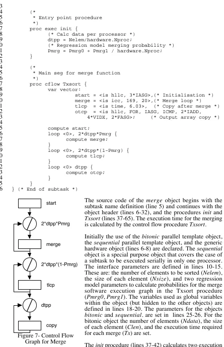
Figure 7- Control Flow Graph for Merge
The source code of the merge object begins with the subtask name definition (line 5) and continues with the object header (lines 6-32), and the procedures init and
Txsort (lines 37-65). The execution time for the merging is calculated by the control flow procedure Txsort.
Initially the use of the bitonic parallel template object, the sequential parallel template object, and the generic hardware object (lines 6-8) are declared. The sequential
object is a special purpose object that covers the case of a subtask to be executed serially in only one processor. The interface parameters are defined in lines 10-15. These are: the number of elements to be sorted (Nelem), the size of each element (Nsize), and two regression model parameters to calculate probabilities for the merge software execution graph in the Txsort procedure (Pmrg0, Pmrg1). The variables used as global variables within the object (but hidden to the other objects) are defined in lines 18-20. The parameters for the objects
bitonic and sequential. are set in lines 25-26. For the bitonic object the number of elements (Ndata), the size of each element (Clen), and the execution time required for each merge (Tx) are set.
parameters, dtpp (data elements per processor) and Pmrg (the probability for the merge loop to be finished in the Txsort control flow graph). The control flow procedure Txsort (lines 47-65) evaluates the graph shown in Figure7. The resource usage of the graph nodes is defined in lines 48-53. These are vectors and include different types of resource usage information. The parameters start and otcp are high level language resource usage vectors, the parameter tlcp is execution time, and the parameter merge
is an instruction level resource usage vector. The control flow graph is described in lines 55-64. The compute statement accepts one argument which is a resource usage vector while the loop statements first argument is a resource usage vector representing the loop overhead per iteration, and the second argument defines the number of repetitions. In all cases the loop overhead has been considered zero.
Parallel Template (bitonic)
(*
1
* bitonic.la: Bitonic parallel template
2
*)
3 4
partmp bitonic {
5 6
include hardware; (* Generic Hardware *)
7
include la; (* Chips System Parameters *)
8 9
(* Interface *)
10
var dtdp numeric:
11
Ndata = 1024, (* Number of Data *)
12
Clen = 4, (* Communication size in bytes *)
13
Tx = 0; (* Processing per bitonic stage *)
14 15
(* External static *)
16
var scope numeric:
17
dtpp; (* Data per processor *)
18 19
option {
20
nstage= Log2(hardware.Nproc), (* Number of stages *)
21
seval = 1 (* Evaluate for each step *)
22
}
23 24
(* Entry point *)
25
proc exec init {
26
(* If first stage then initialise variables *)
27
if la.stage == 1 then
28
call InitVar;
29 30
(* Call evaluation for stage *)
31 call EvalStage; 32 } 33 34
(* InitVar - Initialise Variables *)
35
proc exec InitVar {
36
dtpp = Clen * Ndata;
37
}
38 39
(* Evaluation for each stage *)
40
proc exec EvalStage {
41
var numeric
42
phase, (* Communication phases *)
43
tproc; (* Target processor *)
44 45
phase = la.stage;
46
while( phase > 0 ) {
47
(* Communication Stage for Grid *)
48
step inpcom {
tproc = power(2, phase-1);
50
(*
51
* Communication arguments: Size, From, To
52
*)
53
confdev dtpp*Clen, 0, tproc;
54
}
55
phase = phase - 1;
56
}
57 58
(* And processing stage *)
59
step cpu {
60
(* Set Execution stage *)
61
confdev Tx;
62
}
63
}
64 65
} (* End of partmp *)
66
The name of the parallel template object bitonic is defined in line 5. The header of the object (lines 7-23) contains the definition of other objects which are used, the declaration of the interface parameters, and the setting of the options of the objects. The parallel template uses the generic hardware object and the special purpose object
la that includes parameters related to the status of the CHIP3S run-time evaluation
system. The options that are set are: the number of stages of the parallel algorithm, and the flag seval that configures the CHIP3S run-time system to evaluate the object once
in each stage.
The procedure init is executed for each stage (lines 26-33). Only during the first execution, the procedure InitVar is called to initialise the variable dtdp (data elements per processor). To identify the first execution, the parameter stage of the la object is used (line 28). This parameter is modified by the CHIP3S run-time system and holds
the current evaluation stage number. During the execution of every stage the procedure
EvalStage is called (line 32).
The execution procedure EvalStage is defined in lines 36-38. It describes the computation-communication pattern of the bitonic template for each stage of the parallel algorithm. The algorithm has a number of communication steps and a single computation step in each stage. The communication steps are described in lines 47-57. The while loop determines the number of communication steps (which depends on the current stage of the algorithm). The parameters of each communication step are calculated in the while loop, and set in line 54 with the confdev statement. The first argument of this statement is the size of the communication, the second is the source processor, and the third is the destination processor. Finally in lines 60-63 the computation step is defined. The confdev statement in line 62 determines the time required for this computation phase.
6. Summary & Future Extensions
A number of future extensions will be incorporated into future versions of the CHIP3S
language. These include:
• Bottleneck Analysis: The operations and use of hardware resources can be analysed by ranking them in order of time costs. By doing this, the predominant classes of operations can be identified as bottlenecks in the overall performance of the system. Such an analysis can be incorporated as a future extension to the CHIP3S
toolset. This is being investigated within the PEPS project [PEPS94b].
• Overlapping Computation-Communication: One of the features of the modern parallel systems is the ability to overlap the computation and the communication stages of an algorithm. This is a feature that is not currently supported by CHIP3S
and requires extensions in the syntax of the parallel template and extensions to the hardware models to support asynchronous communication.
• Heterogeneous Processing: The parallel template currently assumes that all processors perform the same computation [Gehringer88, Jamieson87]. However there are several classes of algorithms that require the use of different computations assigned to groups of processors. This feature will be supported extending the CHIP3S language and the evaluation engine to allow the creation of
trees of computation-communication patterns and use of barriers to synchronise them.
• Language Syntax Extensions for Different Topologies: One of the issues that effect the re-usability of the parallel template objects is the mapping of the communication pattern onto the network topology. This currently can be achieved by the explicit use of different user procedures to handle communication patterns for different inter-connection network topologies. A support of this feature from within the syntax of the language will enforce the re-usability of the parallel template objects.
• Embedded Mathematica Code: Although the language supports a wide range of general purpose statements, in some cases the use of the Mathematica language might be required. For example, the use of a special purpose Mathematica library that supports advanced statistical functions might be required in a performance study. The use of embedded Mathematica statements in the CHIP3S language will
be a future extension.
• Debugging: There is the need of a debugging feature to be built into the CHIP3S
language. This will allow the user to monitor the use of the objects, the value of the options and interface parameters, and the sequence of internal procedure calls.
• Library of Generics: Warwick's characterisation work includes the examination of a range of application areas in order to identify the computational core (also termed generics) which are common across several applications [PEPS93]. Ten generics have been selected, including curve fitting, fast fourier transform, matrix multiplication, etc., and have been further characterised [PEPS94a]. A model library of generics will be developed for the CHIP3S language, which can be used
as subtask components in future application studies.
The CHIP3S language, by providing characterisation model reusability, allows easy
Bibliography
[Gehringer88] E.F. Gehringer, D.P. Siewiorek, and Z. Segall, Parallel Processing: The Cm*
Experience, Digital Press, 1988.
[Jamieson87] L.H. Jamieson, Characterizing Parallel Algorithms, L.H. Jamieson, D. Gannon, and
R.J. Douglas (Eds.), MIT Press, 1987, pp. 65-100.
[Miller90] B.P. Miller, M. Clark, J. Hollingsworth, S. Kierstead, S.S. Lim, and T. Torewski,
IPS-2: The Second Generation of Parallel Program Measurement System, IEEE
Trans. on Parallel and Distributed Systems, vol. 1, no. 2, 1990, pp. 206-217.
[Nudd93] G.R. Nudd, E. Papaefstathiou, Y. Papay, T.J. Atherton, C.T. Clarke, D.J.
Kerbyson, A.F. Stratton, R. Ziani, and J. Zemerly, A Layered Approach to the Characterisation of Parallel Systems for Performance Prediction, In: Proc. of Performance Evaluation of Parallel Systems, Coventry, UK, 1993, pp. 26-34.
[Papaefstathiou93] E. Papaefstathiou, D.J. Kerbyson, Characterising Parallel Systems Focusing in
Re-Usability, PEPS Bulletin, No. 2, November 1993, pp. 5-6.
[Papaefstathiou94a] E. Papaefstathiou, D.J. Kerbyson, G.R. Nudd, A Layered Approach to Parallel Software Performance Prediction: A Case Study, In: Proc. International
Conference Massively Parallel Processing, Applications and Development, Delft, Holland, June 1994.
[Papaefstathiou94b] E. Papaefstathiou, D.J. Kerbyson, G.R. Nudd, T.J. Atherton, Comparisions of Resource Models within a Parallel System Characterisation Framework, submitted to Parallel Computing, 1994.
[Parashar93] M. Parashar, S. Hariri, G.C. Fox, An Interpretive Framework for Application
Performance Prediction, Technical Report SCCS-479, Syracuse University, USA,
1993.
[Pease91] D. Pease, A. Ghafoor, I. Ahmad, L.D. Andrews, K. Foudil-Bey, and E.T.
Karpinski, PAWS: A Performance Evaluation Tool for Parallel Computing
Systems, IEEE Computer, 18-29, January 1991.
[PEPS93] Characterisation of Processing Needs, Final Report D5.1, ESPRIT 6962
-Performance Evaluation of Parallel Systems (PEPS), Parallel Systems Group, University of Warwick, Coventry, UK, 1993.
[PEPS94a] Parallelisation of Generics, Interim Report D5.3, ESPRIT 6962 - Performance
Evaluation of Parallel Systems (PEPS), Parallel Systems Group, University of Warwick, Coventry, UK, 1994.
[PEPS94b] Analysis of Bottlenecks, Interim Report D5.4, ESPRIT 6962 - Performance
Evaluation of Parallel Systems (PEPS), Parallel Systems Group, University of Warwick, Coventry, UK, 1994.
[Reed92] D.A. Reed, R. Aydt, T.M. Madhyastha, R.J. Nose, K.A. Shields, and B.W.
Appendix A - YACC Parser Code
%{ /*
* CHIPS Compiler * chips.y
* Compiler Parser Specification
* * Parallel Systems Group, DCS, University of Warwick * Ver. 1.50 (23/01/95)
*/
#include <stdio.h>
%}
%union {
char* string; /* String token value */ float number; /* Number token value */ }
%token APPLICATION SUBTASK PARTMP INCLUDE VAR LINK OPTION PROC %token CFLOW COMPUTE LOOP CALL CASE
%token EXEC IF THEN ELSE WHILE BREAK CONTINUE PRINT %token RETURN EXIT DIM FREE STEP CONFDEV
%token NUMERIC VECTOR STRING IS ARRAY NUMBER %token GTE LSE EQL NEQ
%token <string> IDENTIFIER STRCONST
%nonassoc THEN %nonassoc ELSE
%left '*' '/' %left '+' '-'
%left '<' '>' GTE LSE %left EQL NEQ
%nonassoc UMINUS UPLUS %nonassoc EXPLST
%%
/* Object Definition */
program: APPLICATION IDENTIFIER '{'include_lst vardef_lst link_stm option_stm procedure_lst '}'
| SUBTASK IDENTIFIER '{' include_lst vardef_lst link_stm option_stm procedure_lst '}'
| PARTMP IDENTIFIER '{' include_lst vardef_lst option_stm procedure_lst '}'
;
/* Include statement */ include_lst: /* Empty */
| include_lst include_stm ;
include_stm: INCLUDE IDENTIFIER ';' ;
/* Variable definition */ vardef_lst: /* Empty */
;
vardef_stm: VAR IDENTIFIER vartype ':' var_lst ';'
var_lst: var_opt
| var_lst ',' var_opt ;
var_opt: assignment_opt | IDENTIFIER ;
/* Linking statement */ link_stm: /* Empty */
| LINK '{' link_body '}' ;
link_body: link_opt
| link_body link_opt ;
link_opt: IDENTIFIER ':' assignment_lst ';' ;
/* Option statement */
option_stm: OPTION '{' option_body '}' ;
option_body: assignment_lst ;
/* Procedure List */ procedure_lst: /* Empty */
| procedure_lst procedure_def ;
procedure_def: proc_cflow
| proc_exec
;
/* Control Flow Procedures */
proc_cflow: PROC CFLOW IDENTIFIER argument_lst '{' locvar_lst cflow_lst '}'
;
cflow_lst: /* Empty */
| cflow_lst cflow_stm ;
cflow_stm: COMPUTE vector ';'
| LOOP vector ',' expression '{' cflow_lst '}' | CASE vector '{' case_lst '}'
| CALL IDENTIFIER ';'
| CALL IDENTIFIER '(' expression_lst ')' ';' ;
case_lst: case_opt
| case_lst case_opt ;
/* Execution procedure */
proc_exec: PROC EXEC IDENTIFIER argument_lst '{' locvar_lst exec_lst '}'
;
exec_lst: /* Empty */
| exec_lst exec_stm ;
exec_stm: '{' exec_lst '}' | assignment_stm ';'
| IF expression THEN exec_stm
| IF expression exec_stm ELSE exec_stm | WHILE '(' expression ')' exec_stm
| BREAK ';'
| CONTINUE ';'
| PRINT expression_lst ';' | CALL IDENTIFIER ';'
| CALL IDENTIFIER '(' expression_lst ')' ';' | RETURN ';'
| RETURN expression ';'
| EXIT ';'
| DIM IDENTIFIER ',' expression ';' | FREE IDENTIFIER ';'
| STEP '{' exec_lst '}' | CONFDEV expression_lst ';' ;
/* Other procedure related stuff */ argument_lst: argument_opt
| argument_lst argument_opt ;
argument_opt: VAR identifier_lst ';' ;
locvar_lst: /* Empty */
| locvar_lst locvar_opt ;
locvar_opt: VAR vartype ':' var_lst ';' ;
/* Data Presentation & Manipulation */ vartype: NUMERIC
| VECTOR
| STRING
;
assignment_lst: assignment_stm
| assignment_lst ',' assignment_stm ;
assignment_stm: assignment_opt ';'
assignment_opt: IDENTIFIER '=' expression | IDENTIFIER '=' vector_const | IDENTIFIER '=' STRCONST ;
expression_lst: expression %prec EXPLST
expression: expression '+' expression | expression '-' expression | expression '*' expression | expression '/' expression | expression '>' expression | expression '<' expression | expression GTE expression | expression LSE expression | expression EQL expression | expression NEQ expression | '-' expression %prec UMINUS | '+' expression %prec UPLUS | '(' expression ')'
| variable
| IDENTIFIER '(' expression_lst ')' | IDENTIFIER '(' ')'
| NUMBER
;
variable: IDENTIFIER
| IDENTIFIER '[' expression ']' | IDENTIFIER '.' IDENTIFIER ;
vector: vector_const | IDENTIFIER ;
vector_const: '<' IS IDENTIFIER ',' expression_lst '>' | '<' NUMBER '>'
;
/* Miscellaneous Definitions */ identifier_lst: IDENTIFIER
| identifier_lst ',' IDENTIFIER
%%
main() {
yyparse(); }
yyerror(char* msg) {
Appendix B - Lex Lexical Analyser Code
%{ /*
* CHIPS Compiler * chips.l
* Compiler Lexical Analyser
* * Parallel Systems Group, DCS, University of Warwick * Ver. 1.50 (23/01/95)
*/
#include <string.h> #include "chips.tab.h"
%}
%x COMMENT STRST
id [A-Za-z][A-Za-z0-9_]*
number ([0-9]+|([0-9]*\.[0-9]+)([eE][-+]?[0-9]+)?)
ws [ \t]+
nl \n
%%
"(*" BEGIN COMMENT; <COMMENT>. ;
<COMMENT>\n
<COMMENT>"*)" BEGIN INITIAL;
\" BEGIN STRST; <STRST>[^\"]* {
yylval.string = strdup(yytext); return STRCONST;
}
<STRST>\" BEGIN INITIAL;
application { return APPLICATION; } subtask { return SUBTASK; } partmp { return PARTMP; } include { return INCLUDE; } var { return VAR; } link { return LINK; } option { return OPTION; } proc { return PROC; } cflow { return CFLOW; } compute { return COMPUTE; } loop { return LOOP; } call { return CALL; } case { return CASE; } exec { return EXEC; } if { return IF; } then { return THEN; } else { return ELSE; } while { return WHILE; } break { return BREAK; } continue { return CONTINUE; } print { return PRINT; }
dim { return DIM; } free { return FREE; } step { return STEP; } confdev { return CONFDEV; } numeric { return NUMERIC; } vector { return VECTOR; } string { return STRING; } is { return IS; } array { return ARRAY; }
{number} {
yylval.number = atof(yytext); return NUMBER;
}
{ws} ;
{id} {
yylval.string = strdup(yytext); return IDENTIFIER;
}
{nl} ;
. { return yytext[0]; }