Structure of Iron-Based Cladding Layer on Al-Mg-Si Alloy Coated
by a Resistance Seam Welding Method
Wenqin Wang
1,+, Tomiko Yamaguchi
1and Kazumasa Nishio
21Department of Materials and Science, Kyushu Institute of Technology, Fukuoka 804-8550, Japan 2Nishinippon Institute of Technology, Fukuoka 800-0344, Japan
Iron-based cladding layers were successfully fabricated on the 2 mm thick Al-Mg-Si (A6061) alloys to improve the wear resistance of the substrate by a resistance seam welding (RSEW) method. Microstructure showed that the cladding layer consisted of the high carbon iron alloy powders (SHA) reinforcement, A6061 binder and Fe-Al phases. The Fe-Al phases had two kinds of micro-structured morphologies: a needle-like phase in the A6061 identified as FeAl3, and a planer transition phase at the A6061/SHA powders interface identified as Fe2Al5and FeAl3. A ball-on-disc test was carried out to evaluate the wear resistance of the cladding layers and the wear mechanism was discussed by observing the worn surfaces. Furthermore, the relationship of welding current and the microstructure, as well as the wear resistance of the cladding layer, were also investigated. The results showed that the wear resistance of the cladding layer increased with the increase of the welding current and the best wear performance was found at the welding current of 3.0 kA, where the wear rate was near two orders of magnitude less than the substrate. It was also suggested that the FeAl3in the cladding layer had a critical role to improve the wear resistance. Moreover, the wear mechanisms of the cladding layer changed from adhesion and delaminate to adhesion with the increase of the welding current.
[doi:10.2320/matertrans.M2014242]
(Received July 2, 2014; Accepted August 25, 2014; Published October 10, 2014)
Keywords: aluminum alloys, cladding layer, hardness, wear resistance, resistance seam welding
1. Introduction
Aluminum and its alloys have the characteristics of low density, high specific strength,1)good electrical and thermal
conductivity and good corrosion resistance. Therefore, they are widely used in many engineering applications such as automotive and aerospace.2)However, the surface properties
of aluminum alloys, in particular the poor wear resistance, have limited their applicability in certain cases.3) Recently,
fabrication of cladding layers on the surface of aluminum alloy has been proven to be an effective method to improve the hardness and wear resistance of the substrate. In this respect, several surface treatment techniques have been successfully applied to produce the hard and high wear resistance cladding layers on various aluminum alloys, such as thermal spraying49) and laser surface alloying.3,1013) Recently, research about thermal spraying process has been focused on wear resistance coating on Al alloys substrate. K. Nakata et al.7)successfully fabricated Al-Si binary alloy
coating with 200 µm in thickness on 6 mm thickness A6063 aluminum alloy substrate. A. Edrisyet al.8)also produced a
250 µm coating on the surface of 5 mm thickness 319 Al substrate. Laser surface alloying technology is the most popular technology in enhancing surface properties, capable of coating a thick layer in short operating time. A 1.5 mm thickness hard surface layer consisting of Ni-Al and Ti-Al intermetallic compounds was synthesized on a 10 mm thickness AA6061 plate by laser surface alloying technology by H. C. Man et al.3) Moreover, to obtain the high wear resistance of aluminum alloys, G. Y. Liang et al.14) treated the wear resistance material by combining plasma spraying with laser technology on the 10 mm thickness aluminum alloy plates. The most attactive advantage of these techniques is that they could form thick cladding layers in the order of millimeters within a short time by using a high energy
density heat source. However, owing to the low melting point of aluminum alloys, the high heat generation could affect the internal properties of the thin substrates, so it is still a challenge to use the above-mentioned technologies for the preparation of wear resistance cladding layer on the thin aluminum alloy plate.
On the other hand, other technologies such as physical vapor deposition (PVD),15) electroplating16) and chemical
vapor deposition (CVD)17)are suitable for the thin aluminum
plate, but the thickness of the coatings is approximately several tens of micro-millimeters with low performance. They are easy to be completely destroyed when suffered high load or long-term wear. To the best of our knowledge, there is still no convenient and effective technology to fabricate the thick cladding layers on the surface of the thin aluminum alloys for wide potential applications in the weight-saving industry. Therefore, it is an urgent and challenging issue to find a suitable technique to fabricate thicker layers on the thin aluminum alloy plates.
Resistance seam welding (RSEW) process is a typical joining method of thin metal sheets and widely employed to fabricate the fuel tanks of automobiles due to its high productivity.18,19)The RSEW method uses joule heating as a
heat source; it has low heat generation on aluminum alloy substrates owing to their low electrical resistivity and high thermal conductivity. So it could be expected that, by employing the RSEW method as surface treatment technique, the challenge to form a thick cladding layer on the surface of thin aluminum alloys would be resolved. Moreover, iron-based alloys have the merits of low cost, versatility, good electric conductivity, and good wear resistance.20)Therefore, in this study, an attempt to produce thick iron-based cladding layers with wear resistance on 2 mm thick Al-Mg-Si alloy (A6061) plate has investigated using RSEW method with high carbon iron alloy (SHA) powders. The relationship between welding current and the microstructure, as well as wear resistance, were also studied.
+Graduate Student, Kyushu Institute of Technology
2. Experimental Procedures
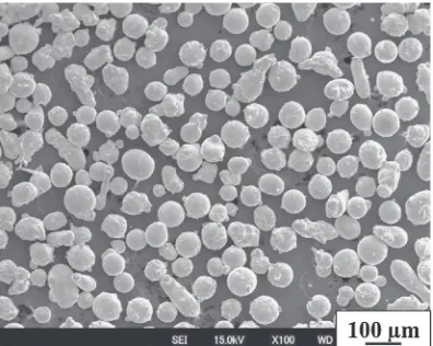
Al-Mg-Si alloy A6061 plates (T6) with dimensions of 2©30©150 mm were used as substrates. Microsphere SHA powders with size of 60³90 µm (see Fig. 1) were used as cladding materials. The chemical compositions of the A6061 substrate and SHA powders are shown in Table 1.
The A6061 surface was polished by emery paper (#240) to remove the oxides and cleaned with acetone, and then 800 µm thickness layer of the SHA powders were preplaced on the surface of A6061 by using an organic binder as shown in Fig. 2(a). A 100 µm thickness SUS304 foil was covered on the powder layer to protect the electrodes. Moreover, it is expected that the fabrication of the cladding layer was relatively easier because of the deposition of SUS304 foil, which can generate more joule heating due to its great electrical resistance. Finally, the samples were treated by RSEW method as shown in Fig. 2(b). The electrodes had dimensions of 65 mm in diameter and 2 mm in width. The welding conditions are given in the Table 2. All the samples were welded at speed of 0.5 m/min and electrode force of 735 N. The different welding currents of 2.6, 2.8 and 3.0 kA were used to exam the effect of welding current on the microstructure and wear resistance of the cladding layers.
The microstructures of the cladding layer were charac-terized by field emission scanning electron microscopy (FE-SEM, JSM-6701, JEOL, Japan), electron probe micro-analyser (EPMA, JXA-8530F, JEOL, Japan) and
trans-mission electron microscope (TEM, H-9000NAR, JEOL). Wearing tests were performed by using ball-on-disc setup (FPR-2000, Japan). A 5 mm diameter Al2O3ball was taken as
the counterface material. All the tests were carried out at room temperature under a normal load of 4.9 N for different times (1, 2 and 3 hours) with sliding speed of 0.64 m/s. The radius of the traveling circle of the ball on the disc was 30 mm and reciprocating stroke angle was 20° and reciprocating stroke length was about 10.4 mm. The surfaces of the samples were polished with 1200 grit and cleaned with ethanol prior to testing. The coefficient of friction (COF) of the speciments was recorded during the wear tests. After wearing test, the abrasion volumes (V) with different time were calculated by examining the wearing surface with three dimension scanning electron microscope (3D-SEM, ERA-8800, Elionix, Japan). The wear mechanism was investigated by field emission scanning electron microscopy (FE-SEM, JSM-6701, JEOL, Japan) with energy dispersive X-ray analysis (EDX) in combination. Moreover, nano-indentation test (ENT-1100a, ELIONIX) was employed to evaluate the hardness by using a load of 2.94 m N and 1 second dwell time to explore the wear mechanism.
3. Results and Discussions
[image:2.595.71.269.70.228.2]3.1 Microstructure of the cladding layers
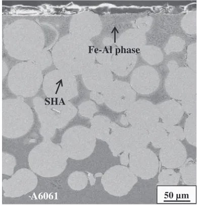
Figure 3 shows the typical cross-sectional view of the specimen formed at the welding current of 2.6 kA. A
Fig. 1 SEM images of SHA powders.
Table 1 Chemical compositions of A6061 substrate and SHA powders (mass%).
Element C Mg Si Ni Cr Mo Al Fe
A6061 ® 1.18 0.6 ® 0.11 ® Bal. ®
SHA 4.99 ® 0.99 4.83 9.84 4.92 ® Bal.
(a) (b)
SHA Powders 50
2 0.8
A6061
2
Electrode wheel
SUS 304 foil
Electrode wheel SHA Powders
A6061
Fig. 2 Schematic diagram of (a) sample, (b) resistance seam welding method.
Table 2 Conditions of resistance seam welding.
Condition Welding speed (m/min)
Electrode Force (N)
Welding current (kA)
[image:2.595.80.539.70.421.2] [image:2.595.303.548.94.135.2]cladding layer with thickness about 400 µm was obtained. The cladding layer composed of microsphere SHA particles and molten A6061 alloy, and the latter acted as a binder. Furthermore, the cladding layer/substrate interface had no visible cracks or delamination, implying that the cladding layer and substrate were well bonded, which should thank to the A6061 binder. Besides, some Fe-Al phases with irregular morphology in the molten A6061 alloy could be also observed. During the welding process, the surface of the A6061 substrate in the welded joint was molten and then entered into the top of the cladding layer because of capillary
action. Therefore, the formation of Fe-Al phases could be explained by the diffusion reaction when molten aluminum was in contact with solid iron.2124) Moreover, the amount
of Fe-Al phases decreased gradually from the near surface region to near the cladding layer-substrate interface region, and finally disappeared on the substrate. This might be related to the deposition of SUS304 with high electrical resistance on the surface of the powder layer, and thus led to higher heat generated on the surface of the cladding layer. Similar results could be also obtained in the samples at 2.8 and 3.0 kA welding current.
Figure 4 shows microstructures near the surface region of the cladding layers made at different welding current. The irregular Fe-Al phases among the SHA powders could be observed in the Fig. 4(a), (c), and (d). From Fig. 4(b), the enlarged view of Fe-Al phases in Fig. 4(a), it could be clearly observed that the Fe-Al phases with irregular needle-like morphology were precipitated from the molten A6061 alloy. Besides, a Fe-Al transition layer with a closely planer morphology at the SHA powders/molten A6061 alloy interface can be also observed. Furthermore, some nano-cracks could also be observed in the Fe-Al phase which might suggest that the stress was generated during the diffusion reaction. Moreover, needle-like Fe-Al phase became much coarser with the increase of the welding current. When the welding current was 3.0 kA, the amount of the needle-like Fe-Al phases obviously increased and agglomerated together and there were nearly no molten A6061 alloy could be observed. This could be explained by the faster diffusion reaction, which led to the faster growth rate of Fe-Al phase due to the temperature increased by increasing the welding current.25)It
should be mentioned that, the SHA powders still kept their
A6061 50 µm
SHA
Fe-Al phase
Fig. 3 Cross-section morphology of the cladding layer (I=2.6 kA).
[image:3.595.71.266.71.274.2] [image:3.595.112.484.482.758.2]microsphere shape and dimension in diameter at the welding current of 2.6 kA. However, when it increased to 3.0 kA, the SHA powders partly melt and agglomerated together, which can be approved by their shapelessness and bigger size. This difference was also the consequence of the different heat generation in these samples.
3.2 Identification and formation mechanism of the Fe-Al phases
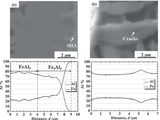
To identify the Fe-Al phases in the Fig. 4, EPMA line analysis was carried out. Figure 5 shows the SEM images and distributions of Fe and Al elements across the Fe-Al transition layer and the needle-like Fe-Al phase. According to the Fe-Al binary phase diagram, in the transition layer, the phase adhering to the SHA powder was considered as Fe2Al5
and the one adhering to A6061 alloy might be FeAl3
(Fig. 5(a)), which was proven by previous literatures.2629) From Fig. 5(b), the value of Al atomic concentration kept stable at 75%, which meant the needle-like Fe-Al phase could be FeAl3. Furthermore, it revealed that the Al atomic
concentration detected in the crack was slightly higher than that in the FeAl3.
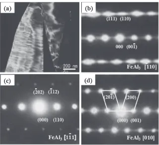
In order to further characterize the needle-like Fe-Al phase in the cladding layer, the transmission electron microscopy (TEM) analysis was carried out. Figure 6 shows the bright field imaging (BFI) and the corresponding selected area electron diffraction (SAD) patterns. The needle-like structure of the Fe-Al phase observed in Fig. 6(a) was similar to the SEM images obtained in Fig. 4(b) and Fig. 5(b). The SAD patterns were obtained by changing the direction of the incident electron beam, which could be indexed as ½110,
½111and [010] axes (Fig. 6(b)-(d)). According to these SAD patterns, it could be concluded that the needle-like Fe-Al phase in BFI images was FeAl3.30,31) The result is in
accordance with the result of EPMA line analysis. Moreover, the characteristic feature of twinning with refection plane (001) along [010] axe could also be observed in Fig. 6(d).32)
From the analysis above, it could be concluded that the intermetallic compounds in the cladding layer were Fe2Al5
and FeAl3, and the latter was the major phase. The formation
manner of the Fe-Al phases in the cladding layers could be considered as shown in Fig. 7. First, the heat was generated at the interface between the A6061 substrate and SHA powders. Since the melting point of A6061 substrate is lower than SHA powders, the surface of A6061 substrate melt and entered into the top of the cladding layer by capillary action. Then the molten A6061 alloy started to contact with the SHA powders as shown in Fig. 7(a). According to the thermody-namic principles, the nucleation of FeAl3 was first located
since the standard Gibbs free energy to form the Fe2Al5 is
higher than FeAl3 (Fig. 7(b)).25) And then, FeAl3 began to
grow, because the diffusion coefficient of the iron into aluminum is much greater than that of the aluminum into iron,26) and the Al atomic concentration near the SHA powder side was decreased. Therefore, the nucleation of Fe2Al5 was formed at the expense of FeAl3. The
trans-formation could be expressed as follows:33)
FeAl3þFeþ2Al!Fe2Al5 ð1Þ
Because the growth coefficient of Fe2Al5 was larger than
the FeAl3,25) the FeAl3 disappeared once the Fe2Al5
nucleation was formed as shown in Fig. 7(c). On the other hand, the FeAl3near the A6061 side continued to grow and
increased the thickness toward A6061 alloy to form the transition layer. Because the temperature in the liquid A6061 alloy was lower than in the SHA powder/liquid A6061 alloy interface, while the FeAl3 grew into the liquid A6061 alloy,
FeAl3changed to needle-like morphology. At the same time,
there was not sufficient energy to form the nucleation of Fe2Al5and thus only FeAl3nucleation was formed and grew
in the liquid A6061 alloy (Fig. 7(d)). In other words, the formation and growth of Fe-Al phase was strongly affected by the thermal conditions and some ambiguities still existed on the Fe-Al phase.
[image:4.595.146.454.70.302.2]3.3 Wear resistance
Table 3 shows the average COF values, wear tracks volume and wear rates of the A6061 substrate and samples with wear time after abrasive test. This is also depicted in Fig. 8. In Fig. 8(a), it could be observed that the COF values of all the cladding layers were relatively lower than the A6061 substrate. For the substrate, the COF remained a
relatively high value of about 0.8 in thefirst 2500 s and then decreased to about 0.5 for the remaining time, however, accompanied with considerablefluctuation. While for all the cladding layers, the COF values were not only relatively lower but also smoother when compared with the substrate and they increased continuously in the first 500 s and then kept stable. The COF value of the cladding layer made in low welding current showed more fluctuation and higher value. The reason might be related to that the surface was rougher due to more A6061 removed from the cladding layer during wear in low welding current. Corresponding to the COF value, the wear volumes of the cladding layers were considerably lower than the substrate and decreased with the welding current increasing as shown in Fig. 8(b). Since the wear track area increased linearly with increasing test time, wear rates were also quantified from the slopes. For the substrate, the average COF value was 0.61 and the wear rate reached a high value of 66.5©10¹3mm3/h. While for the
cladding layers, the average COF decreased to 0.49 and 0.41
[image:5.595.138.459.67.359.2]Fig. 7 Formation mechanism of the Fe-Al phases, (a) molten A6061 alloy began to contact with the SHA powders A6061; (b) formation and growth of nucleation of FeAl3phase; (c) formation and growth of nucleation of Fe2Al5phase; (d) formation of transition phase and needle-like phase.
Table 3 Average coefficient of friction, wear volumes and wear rates of A6061 substrate and samples.
COF Wear track volume (10¹3mm3)
Wear rate (10¹3mm3/h)
1 h 2 h 3 h
A6061 0.61 214 253 348 66.5
Samples
I=2.6 kA 0.49 1.44 2.77 4.65 1.6
I=2.8 kA 0.41 1.05 2.09 3.18 1.1
I=3.0 kA 0.38 0.58 1.31 2.15 0.8
[image:5.595.74.524.397.502.2] [image:5.595.46.291.587.675.2]for the welding current of 2.6 and 2.8 kA and attendant wear rate decreased to 1.6 and 1.1©10¹3mm3/h. The lowest COF (0.39) and wear rate (0.8©10¹3mm3/h) were obtained at welding current of 3.0 kA. Corresponding to the lowest COF, the wear resistance was optimum and improved about two orders of magnitude when compared with the substrate. In addition, it is clear that the improvement of the welding current is beneficial to enhance the wear resistance.
3.4 Wear mechanism
To investigate the wear mechanism of the cladding layer, it is necessary to measure the hardness of the organizations in the cladding layer since the wear resistance of the material has a tight relationship with its hardness.34) However, it is
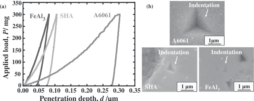
difficult to measure the hardness of Fe-Al phases with Vickers-hardness test due to their small sizes. Therefore, a nano-indentation hardness test was carried out. Figure 9 shows nano-indentation load-depth curves measured on the surface of A6061, SHA and FeAl3 phase in the molten
A6061 and the corresponding indentations after tests. The indentation depths of A6061, SHA and FeAl3 phase were
about 0.3, 0.1 and 0.075 µm and corresponding dynamic nanohardness HIT values were about 1.2, 9.3 and 10.5 GPa
respectively (Fig. 9(a)), suggesting the FeAl3 possessed the
highest hardness. Moreover, from Fig. 9(b), corresponding to the indentation depths, the FeAl3 showed a considerably
smaller indentation than the others. No crack was observed around the indentation of FeAl3 although the FeAl3 was
significantly brittle, indicating the results were reliable under the load of 300 mg. From the results of nano-indentation hardness test, it is suggest that, except the reforcement SHA, the FeAl3phases maybe in favor of the wear resistance in the
cladding layer.
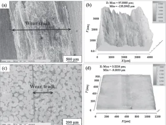
The worn track of the cladding layer at 2.6 kA and the substrate after wear test are summarized in Fig. 10. In Fig. 10(a), it is observed that the substrate suffered a very severe damage with a wear track of about 3 mm in width on the surface. In contrast, the width of wear track of the cladding layer was about 280 µm, indicating very little damage (Fig. 10(c)). Moreover, compared to the recon-structed three dimensional SEM images of the substrate (Fig. 10(b)) and the cladding layer (Fig. 10(d)), it is also clearly observed that the cladding layer exhibited much smoother surface than the substrate. The altitude gradient of the substrate and the cladding layer was 232.4 and 12.4 µm respectively. There was no significant difference in the cladding layers produced at 2.8 and 3.0 kA welding currents. This result could be used to explain the reason that the COF value for the substrate was high and accompanied with considerable fluctuation, while the samples was relatively smaller and more stable since the wear debris for samples were significantly smaller than the substrate. Furthermore, it
Fig. 8 Variations of COF (a) and the wear track volumes, (b) of the cladding layers and the substrate with wear time after wearing tests.
Penetration depth,
d
/µm
A
pplied load,
P
/ mg
0.05
0.00 0.10 0.15 0.20 0.25 0.30 0.35
FeAl3 SHA A6061
1 µm 1µm
1 µm (b)
(a)
50 300
100
0 150 200 250 350
Indentation Indentation
Indentation
FeAl3 SHA
A6061
[image:6.595.106.489.71.216.2] [image:6.595.93.504.255.418.2]could also be concluded that the abrasion losses of the cladding layers were near zero when compared with the substrate.
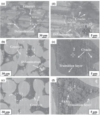
Figure 11 shows the worn surfaces of the cladding layers at different welding current after wearing test. From Fig. 11(a), some deep grooves in the sliding direction and severe delamination could be observed on the worn surface of the cladding layer at 2.6 kA. Since the delamination related to the adhesive mechanism, thus it is reasonable to consider that the wear mechanism of the cladding layers at 2.6 kA was adhesion and delamination mechanism and the latter acted as a dominant mechanism. In contrast, the grooves were relative shallower and the delamination decreased on the surface of the cladding layer at 2.8 kA (Fig. 11(b)). Furthermore, as the welding current increased to 3.0 kA, the delamination disappeared on the worn surface of the cladding layer (Fig. 11(c)). Therefore, we can conclude that the wear mechanism was changed to adhesion for the cladding layer at 3.0 kA. The SEM results were in good agreement with COF value and wear rate results discussed in the Fig. 8.
Higher magnification SEM images of worn surface shown in Fig. 11(a), (b) and (c) are presented in Fig. 11(d), (e) and (f ), respectively. Combined with the result of EDX analysis (Table 4) in point 1, it clearly shows that the delamination material in the cladding layer at 2.6 kA was A6061, implying that the soft A6061 were the main source of removal material during the wear test (Fig. 11(d)). Moreover, some cracks, which could be considered as the origination of the delamination, were also observed on the worn surface. During the wear test, A6061 in the area around these cracks tended to separate from the cladding layer, and thus lead to delamination. The EDX result of point 2 in Fig. 11(e) shows that the Al atomic concentration was 83.9%, so that it could be concluded that the material among SHA powders
consisted of both FeAl3 and A6061 in the cladding layer at
2.8 kA. Moreover, more tiny cracks were located at the worn surface of 2.8 kA. The EDX result of point 3 in Fig. 11(f ) shows that Al atomic concentration was 74.5%, indicating that the FeAl3 was nearly the only phase among SHA
powders, which was in good agreement with the result in Fig. 4(d). It should be noted that the worn surface was free of any delamination resulted from no visible cracks, which revealed a fact that the wear resistance was actually controlled by the amount of FeAl3among SHA powders in
the cladding layers at different welding current.35)On the one hand, the increase of FeAl3phases led to the decrease of the
A6061 in the cladding layer, which meant a decrease of the delaminate material. On the other hand, the FeAl3possessed
higher hardness than SHA powders (proved in Fig. 9) prevented the SHA to Al2O3contact to suffer to the adhesion
wear. Therefore, the presence of FeAl3among SHA powder
prevented the delamination and adhesion damage in the cladding layers. The more the FeAl3phases were formed, the
less the wear lost. It also could be employed to explain the reason that the improvement of the wear resistance increased with the increase of the welding current due to more FeAl3
phases formed in the cladding layer made in high welding current. In Fig. 11(f ), there was no delaminate observed because of the FeAl3phases occupied the spaces among SHA
powders, and thus the cladding layer of 3.0 kA showed the most outstanding wear resistance. Furthermore, since there were no significant difference on the thickness of the transition layer between the Fig. 11(e) and (f ), the effect of Fe-Al transition layer on the wear resistance could be ignored.
[image:7.595.127.470.70.328.2]From the analysis above, the improvement of wear resistance in the cladding layer could be attributed to the following reasons: (1) Compared to the substrate, the SHA
particles acted as a dominant reinforcement against the Al2O3
counterface and helped to minimize the adhesion between the Al2O3ball and the A6061 to prevent the A6061 to suffer
severe damage in the cladding layers. (2) In the different cladding layers, the amount of FeAl3 phases played a
critical role to further reducing the wear damage. Thus, the results indicated that the cladding layers had good wear resistance due to the hard SHA powders and the FeAl3
phases.
In summary, the experimental results showed that iron alloy cladding layers with high wear resistance could be successfully fabricated on A6061 alloy by a resistance seam welding method. Thus, this technique proposed in this paper could be considered as a new method to apply on the modification of the surface of aluminum alloys.
4. Conclusions
(1) The cladding layers consisted of the SHA reinforce-ment, A6061 binder and Fe-Al phases were success-fully fabricated on A6061 substrate by a resistance seam welding method. The formation mechanism of the cladding layer was that the surface of the A6061 substrate was molten and entered into the top of the cladding layer because of a capillary action.
(2) The Fe-Al phases in the cladding layers had two kinds of micro-structured morphologies. A needle-like phase in the molten A6061 alloy was characterized as FeAl3.
Besides, a transition layer Fe-Al phase with planer morphology was observed at the molten A6061/SHA powders interface, which was identified as Fe2Al5and
FeAl3. Moreover, the amount of FeAl3phases gradually
declined with decreasing the welding current.
(3) The FeAl3 (10.5 GPa) possessed a highest value of
nanohardness than SHA (9.3 GPa) and A6061 (1.2 GPa).
[image:8.595.128.470.68.461.2](4) The wear resistance of the cladding layer was improved by increasing the welding current, which was actually due to the increase of the FeAl3. The cladding layer of
Fig. 11 Worn surface of cladding layers (a) I=2.6 kA; (b)I=2.8 kA; (c)I=3.0 kA; (d) (e) (f ) magnification micrograph of (a), (b) and (c).
Table 4 Results of EDX analysis in Fig. 10(d), (e) and (f ) (at%).
Location Al Fe
Point 1 97.2 2.8
Point 2 83.9 16.1
[image:8.595.47.290.525.577.2]3.0 kA was proved to be the best wear performance, where the wear rate was near two orders of magnitude less than the substrate.
(5) The wear mechanism of the cladding layer changed from adhesion and delaminate to adhesion with the increase of the welding current.
REFERENCES
1) C. Poletti, M. Balog, F. Simancik and H. P. Degischer:Acta Mater.58
(2010) 37813789.
2) W. S. Miller, L. Zhuang, J. Bottema, A. J. Wittebrood, P. De Smet, A. Haszler and A. Vieregge:Mater. Sci. Eng. A280(2000) 3749.
3) H. C. Man, S. Zhang and F. T. Cheng:Mater. Lett.61(2007) 4058 4061.
4) A. Edrisy, T. Perry and A. T. Alpas:Metall Mater. Trans. A36(2005) 2737.
5) K. Nakata and M. Ushio:Surf. Coat. Technol.169170(2003) 443 446.
6) M. Magnani, P. H. Suegama, N. Espallargas, S. Dosta, C. S. Fugivara, J. M. Guilemany and A. V. Benedetti:Surf. Coat. Technol.202(2008) 47464757.
7) K. Nakata and M. Ushio:Surf. Coat. Technol.142144(2001) 277 282.
8) A. Edrisy, T. Perry, Y. T. Cheng and A. T. Alpas:Wear251(2001) 10231033.
9) Z. X. Kang, K. Nakata and Y. Y. Li:Surf. Coat. Technol.201(2007) 49995002.
10) M. H. Staia, M. Cruz and Narendra. B Dahotre:Thin Solid Films377 378(2000) 665674.
11) H. C. Man, S. Zhang, T. M. Yue and F. T. Cheng:Surf. Coat. Technol.
148(2001) 136142.
12) S. Yang, N. Chen, W. J. Liu and M. L. Zhong:Mater. Lett.57(2003) 34123416.
13) S. Tomida and K. Nakata:Surf. Coat. Technol.174175(2003) 559 563.
14) G. Y. Liang, T. T. Wong, J. M. K. MacAlpine and J. Y. Su:Surf. Coat.
Technol.127(2000) 232237.
15) T. Tański and K. Labisz:Solid State Phenom.186(2012) 192197.
16) J. Auerswald and H. J. Fecht:J. Electrochem. Soc.157(2010) D199 205.
17) P. U. Arumugam, A. P. Malshe and S. A. Batzer:Surf. Coat. Technol.
200(2006) 33993403.
18) H. Murakawa, H. Minami and T. Kato: Trans. JWRI30(2001) 111 117.
19) A. H. Blom, I. M. Richardson, E. Elzinga and M. de Haas: Sci. Technol. Weld. Join.13(2008) 19.
20) A. Farid and S. J. Gu:Acta Mater.55(2007) 14671477.
21) Y. Tanaka and M. J. Kajihara:Mater. Sci.45(2010) 56765684.
22) A. Bouayad, Ch. Gerometta, A. Belkebir and A. Ambari:Mater. Sci. Eng. A363(2003) 5361.
23) K. Bouché, F. Barbier and A. Coulet:Mater. Sci. Eng. A249(1998) 167175.
24) K. A. Nazari and S. G. Shabestari:J. Alloy. Comd.478(2009) 523 530.
25) W. H. Zhang, D. Q. Sun, L. J. Han, W. Q. Guo and X. M. Qiu:ISIJ Int.
51(2011) 18701877.
26) H. R. Shahverdi, M. R. Ghomashchi, S. Shabestari and J. Hejazi:
J. Mater. Proc. Technol.124(2002) 345352.
27) K. J. Lee and S. J. Kumai:Mater. Trans.47(2006) 11781185.
28) S. S. Nayak, M. Wollgarten, J. Banhart, S. K. Pabi and B. S. Murty:
Mater. Sci. Eng. A527(2010) 23702378.
29) N. Wang, T. Yamaguchi and K. Nishio:J. Japan Inst. Met. Mater.77
(2013) 259267.
30) M. Zelechower, J. Kliś, E. Augustyn, J. Grzonka, D. Stróz, T. Rzychoń and H. Woźnica: Arch. Metall Mater.2(2012) 517524.
31) H. Heidari, H. Alamdari, D. Dubé and R. Schulz:J. Eur. Ceram. Soc.
32(2012) 937945.
32) K. k. Fung, X. D. Zou and C. Y. Yang:Philos. Mag. Lett.55(1987) 27 32.
33) B. K. Chen, Q. S. Chen, H. F. Zhong, X. D. Hao, S. M. Jiang and Q. F. Zhang: J. Chin. Soc. Corros. Protect.33(2013) 188192.
34) M. Vasheghani Farahani, E. Emadoddin, M. Emamy and A. Honarbakhsh Raouf:Mater. Des.54(2014) 361367.