Materials Research Institute for Sustainable Development, National Institute of Advanced Industrial Science and Technology (AIST), Nagoya 463-8560, Japan
2School of Materials Science and Engineering, University of Ulsan, Ulsan 680-749, Korea
In this study, tailor-welded blanks (TWBs) composed of A5052P-O aluminum and AZ31B-O magnesium alloys were produced by the friction stir welding process. The sound surfaces without large defects were successfully obtained at the tool rotation speeds ranging from 1000 to 1400 rpm under the constant tool traverse speed of 300 mm/min, and the surface roughness was decreased in the friction-stir-welded zone (SZ) with the increase in the tool rotation speed. Also for 100, 300 and 500 mm/min, the sound surfaces without large defects were obtained under the constant tool rotation speed of 1400 rpm. The increase of the tool traverse speed led to the decrease in the surface roughness of the SZ. In the SZ, the bonded interface was clearly evident with plastic flow pattern between the aluminum and magnesium alloys, although an onion ring pattern was not formed. During tensile testing, the TWBs were fractured in the SZ at the early stage of the plastic deformation,i.e.strain hardening region, without remarkable area reduction near the fracture region. The TWBs exhibited the similar average tensile strength, showing that there were not noteworthy changes in the tensile strength as a function of the tool rotation speed. The average tensile strength, however, was slightly decreased with the increase in the tool traverse speed. It is noticeable that, in all cases, the joint efficiency of the TWBs exceeded 62%, and the maximum average tensile strength of about 143 MPa was obtained at 1400 rpm under the tool traverse speed of 100 mm/min, which was nearly equivalent to the joint efficiency of about 72%. The average total elongation of the TWBs was about 2% or less considerably lower than those of the base metals, without significant changes as functions of the tool traverse speed and the tool traverse speed.
[doi:10.2320/matertrans.MER2008326]
(Received September 5, 2008; Accepted November 4, 2008; Published December 17, 2008)
Keywords: tailor-welded blank, aluminum alloy, magnesium alloy, friction stir welding, surface roughness, macrostructure, tensile properties, joint efficiency
1. Introduction
Recently, there is increasing interest in aluminum and magnesium alloys in many industrial fields, because of a wide variety of unique properties, especially lightweight properties. For their practical applications, bonding and welding technologies should also be established aside from alloy design, microstructure control, plastic forming, casting and surface treatment etc.
Friction stir welding (FSW) process is one of the attractive technologies for welding of metallic materials. Especially for aluminum1–8) and magnesium9–12) alloys, the FSW process has been actively studied as a new solid state welding technology, since it was invented by The Welding Institute (TWI) in 1991.13)In addition, the FSW has recently gotten a lot of attention also in order to produce tailor-welded blanks (TWBs) composed of dissimilar materials.14–20) However, there were not a lot of researches on dissimilar FSW between the aluminum and magnesium alloys.18–22) Hirano et al.18) have carried out a dissimilar FSW between 1050 aluminum and AZ31 magnesium alloys, and reported that an inter-mediate layer was formed near their bonded interface, which was composed of an intermetallic compound Al12Mg17 and
an undefined compound. Satoet al.19)also have studied on the same system as Hirano et al.,18) although the plate thickness was different. According to their research, a eutectic microstructure was formed in the friction-stir-welded zone (SZ), which was composed of some pores, magnesium solid solution, and a large volume of intermetal-lic compound Al12Mg17. Yan et al.20) have found that
intermetallic compounds, i.e. Al3Mg2 and Al12Mg17, were
formed in the SZ, when the rotating probe was traversed along the centerline of the SZ in a dissimilar FSW between 1060 aluminum and AZ31 magnesium alloys. The above-mentioned previous researches show that the FSW is applicable to the dissimilar bonding between the aluminum and magnesium alloys. The previous researches, however, were mainly performed on the macro- and micro-structure characteristics, and/or hardness properties of the TWBs. Hence, it is difficult to understand fully the influences of principal processing parameters,e.g.tool rotation speed and tool traverse speed etc., on the various mechanical properties of the TWBs produced by the dissimilar FSW between the aluminum and magnesium alloys.
In this context, TWBs composed of A5052P-O aluminum and AZ31B-O magnesium alloys were produced by the FSW process in this study. And then, the influences of the tool rotation speed and tool traverse speed on surface appearance, macrostructure and tensile properties of the TWBs were experimentally investigated.
2. Experimental Procedure
located on the advancing side (AS) and the retreating side (RS), respectively. This was because the arrangement of the base metals may affect the characteristics of the friction-stir-welded (FSWed) plates. The shoulder diameter of the tool was equal to 10 mm. The diameter and height of the probe were 4 and 1.7 mm, respectively. The tool was rotated in a clockwise direction at speeds ranging from 800 to 1600 rpm, and then the probe was inserted into the materials. The rotating tool was traversed at speeds ranging from 100 to 500 mm/min along the weld line perpendicular to the rolling direction of the base metal plates. The tool rotation axis was tilted by 3 to the tool traverse direction during the FSW process.
Macrostructural observations were performed onX–Yand Y–Z planes which were the cross-sections parallel and perpendicular to the tool traverse direction, respectively. In the FSW, processing parameters will exert an effect on surface morphology of the SZ, which affect various charac-teristics of the FSWed plates. Unfortunately, there is little research on the influences of the various processing
param-influences of the tool rotation speed and tool traverse speed on the surface roughness profile of the SZ were investigated. The surface roughness profiles were measured at intervals of 100mmto the tool traverse direction along the centerline on the surface of the SZ by a laser displacement meter (trade name LC-2450, Keyence, Japan). Figure 2 show the geom-etry and dimensions of the tensile test specimen. For the tensile tests, the TWBs were cut perpendicularly to the tool traverse direction, and then machined into the tensile test specimens with a parallel portion of 4 mm wide24 mm long1 mm thick and a fillet radius of 5 mm. The tensile tests were carried out at a constant crosshead speed of 1 mm/ min under room temperature.
3. Results and Discussion
3.1 Influences of tool rotation speed 3.1.1 Surface appearance and morphology
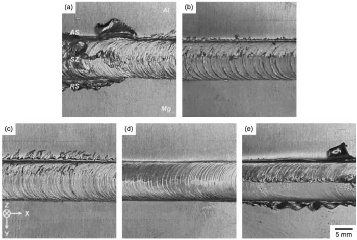
Figure 3 shows the surface appearances of the TWBs produced at the tool rotation speeds of (a) 800, (b) 1000, (c) 1200, (d) 1400 and (e) 1600 rpm under the constant tool traverse speed of 300 mm/min. For (a) 800 rpm, large defects with valley-like structures were discontinuously formed with a large amount of burr to the tool traverse direction (X-axis retreating side are labeled SZ, AS and RS, respectively. And then,X,Zand
Yrepresent the tool traverse direction, the tool rotation axis direction and the rolling direction of the base metals, respectively.
[image:2.595.59.278.73.187.2] [image:2.595.324.529.73.169.2] [image:2.595.122.472.523.758.2]direction) in the SZ with a very rough surface. In contrast, sound surfaces without large defects were successfully obtained at the increased tool rotation speeds of (b) 1000, (c) 1200 and (d) 1400 rpm. In addition, the surface morphol-ogy of the SZ became smoother with the increase in the tool rotation speed. For (e) 1600 rpm, however, large defects presenting as cracks were again formed with a large amount of burr along the tool traverse direction near the center region of the SZ. These results show that there are optimum tool rotation speeds in order to obtain sound surfaces for the dissimilar FSW between the A5052P-O aluminum and AZ31B-O magnesium alloys.
Figure 4 show the surface roughness profiles along the centerlines to the tool traverse direction of the SZ in the TWBs produced at the tool rotation speeds of (a) 800, (b) 1000, (c) 1200, (d) 1400 and (e) 1600 rpm under the constant tool traverse speed of 300 mm/min. Note that the scale of vertical axis is different in each profile. For (a) 800 rpm, the SZ had the very rough surface with the roughness distribution range of 4.64 mm, which was associated with the large macroscopic defects foamed in the SZ. The relatively smooth surfaces were obtained at (b) 1000, (c) 1200 and (d) 1400 rpm, where the sound surfaces without large defects were successfully obtained. In these cases, the roughness distribution ranges were (b) 0.18, (c) 0.12 and (d) 0.08 mm, showing that the surface roughness was decreased with the increase in the tool rotation speed. However, for (e) 1600 rpm, the surface roughness was again increased, and distributed at a range of 5.87 mm, which was attributed to the large macroscopic defect. These results show that there are optimum tool rotation speeds in order to obtain the sound SZ with the smooth surface for the dissimilar FSW between the A5052P-O aluminum and AZ31B-O magnesium alloys.
3.1.2 Macrostructure
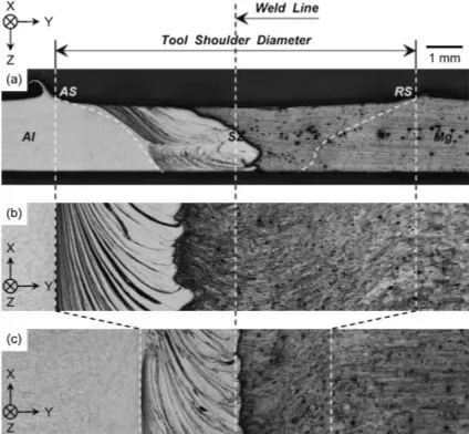
Figure 5 show the typical optical macrographs of the cross-sections of the friction-stir-welded (FSWed) TWB. (a) Y–Z plane was the cross-section perpendicular to the tool traverse direction. And, (b)X–Y plane 1 and (c) 2 were the cross-sections near the top surface and the central region of the SZ, respectively, which were parallel to the tool traverse
direction. Yanet al.20)have reported that cracks were formed in the SZ when the rotating probe was traversed along the center of weld line. In this study, however, no bonding defects were formed near and in the SZ for the tool rotation speeds ranging from 1000 to 1400 rpm, even though the rotating probe was traversed along the center of the weld line. This result shows that there are some optimum conditions for each dissimilar FSW. In all the cross-sections, the bonded interface was clearly evident between the aluminum and magnesium alloys. Plastic flow pattern was also formed in the SZ, which was more clearly observed on the aluminum alloy region. As shown in Fig. 5(a), however, an onion ring pattern was not formed, which was sometimes observed in the SZ between similar materials.6–8)Although a precise conclusion is not yet possible, it is likely that no formation of the onion ring pattern results from differences in plastic flow behavior between the A5052P-O aluminum and AZ31B-O magnesium alloys. As mentioned above, Satoet al.19)have reported that a eutectic microstructure was formed in the SZ by constitu-tional liquation and solidification for a dissimilar FSW between aluminum and magnesium alloys. In this study, however, such solidification microstructure was not formed suggesting that the microstructure of the SZ is dependent on FSW conditions for each system.
3.1.3 Tensile properties
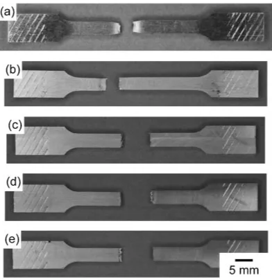
Figure 6 shows the appearances of the tensile tested specimens of (a) the A5052P-O aluminum alloy and (b) AZ31B-O magnesium alloy plates, and the TWBs produced at the tool rotation speeds of (c) 1000, (d) 1200 and (e) 1400 rpm under the constant tool traverse speed of 300 mm/ min. The (a) A5052P-O aluminum alloy and (b) AZ31B-O magnesium alloy plates were fractured in the parallel portion. And, in all cases, the FSWed TWBs were fractured near the central region of the parallel portion, suggesting that the fracture occurred in the SZ without remarkable area reduction near the fracture region.
Figure 7 shows the typical nominal stress-strain curves for the tensile deformation of the A5052P-O aluminum alloy and Fig. 4 Surface roughness profiles along the centerlines to the tool traverse
direction of the friction-stir-welded zone in the tailor-welded blanks produced at the tool rotation speeds of (a) 800, (b) 1000, (c) 1200, (d) 1400 and (e) 1600 rpm under the constant tool traverse speed of 300 mm/min. Note that the scale of vertical axis is different in each profile.
Fig. 5 Typical optical macrographs of the cross-sections of the tailor-welded blank: (a)Y–Zplane, (b)X–Yplane 1 (near the top surface) and (c)
[image:3.595.66.270.70.219.2] [image:3.595.320.532.73.269.2]AZ31B-O magnesium alloy plates. In both cases, the curves exhibited a tendency similar to a typical stress-strain curve of other aluminum and magnesium alloys. Namely, the stress was abruptly increased with elastic strain at an early stage, and then the flow curve exhibited a continuous type of transition behavior from elastic to plastic deformation which produces a yield point in the typical stress-strain curve of aluminum and magnesium alloys. In the plastic deformation region, the stress increased with plastic strain, and reached the maximum value because of strain strengthening, and then dropped continuously with further strain until fracture. Serration phenomenon was clearly observed only in the plastic deformation region of the aluminum alloy. The magnesium alloy had higher tensile and yield strengths than the aluminum alloy. The elongation of the aluminum alloy, however, was larger than that of the magnesium alloy.
Figure 8 shows the typical nominal stress-strain curves for the tensile deformation of the TWBs produced at the tool rotation speeds of 1000, 1200 and 1400 rpm under the constant tool traverse speed of 300 mm/min. For comparison, the enlarged curves for the A5052P-O aluminum and
AZ31B-O magnesium alloys were also shown. In all the TWBs, the curves had a tendency similar to those of the base metals. The TWBs, however, were fractured at the early stage of the plastic deformation,i.e.strain hardening region, after the curves exhibited a continuous type of transition behavior from elastic to plastic deformation. As a result, the TWBs exhibited lower tensile strength and elongation than those of the base metals, although their yield strengths were similar to that of the aluminum alloy.
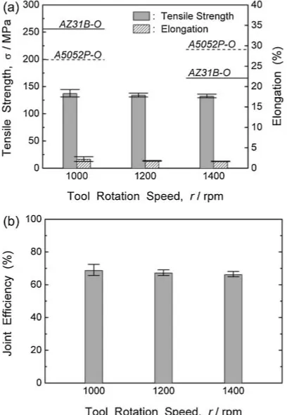
Figure 9 shows the influence of the tool rotation speed on the (a) average ultimate tensile strength and total elongation, and (b) joint efficiency of the TWBs, which are produced under the constant tool traverse speed of 300 mm/min. The broken and solid lines show the average ultimate tensile strength and elongation of the A5052P-O aluminum and AZ31B-O magnesium alloys, respectively. And then, the positive and negative error bars represent the maximum and minimum values, respectively. The joint efficiency was calculated by dividing the tensile strengths of the TWBs by that of the aluminum alloy. The magnesium alloy exhibited the average tensile strength of about 256 MPa, which was higher than that of the aluminum alloy (about 200 MPa). In all the tool rotation speeds, the TWBs had the similar tensile strength, showing that there were not noteworthy changes in the tensile strength as a function of the tool rotation speed. It is noticeable that, in all cases, the average joint efficiency of the TWBs exceeded 66%, and the maximum average tensile strength of about 137 MPa was obtained at 1000 rpm, which was nearly equivalent to the joint efficiency of about 69%. Unfortunately, however, the average elongation of the TWBs was about 2% or less considerably lower than those of the base metals, without significant change as a function of the tool rotation speed. The previous researches have reported that fracture of FSWed specimens occurred near intermetallic compounds such as Al12Mg17 and Al3Mg2
which were formed in the SZ during dissimilar FSW.18,22) Hence, it is believed that formation and/or distribution of the intermetallic compounds should be controlled for further improvement of the mechanical properties by various processing parameters.
Fig. 6 Appearances of the tensile tested specimens of (a) the A5052P-O aluminum alloy and (b) AZ31B-O magnesium alloy plates, and the tailor-welded blanks produced at the tool rotation speeds of (c) 1000, (d) 1200 and (e) 1400 rpm under the constant tool traverse speed of 300 mm/min.
Fig. 7 Typical nominal stress-strain curves for the tensile deformation of the A5052P-O aluminum alloy and AZ31B-O magnesium alloy plates.
[image:4.595.71.267.71.273.2] [image:4.595.320.536.72.226.2] [image:4.595.67.277.342.489.2]3.2 Influences of tool traverse speed 3.2.1 Surface appearance and morphology
Figure 10 shows the surface appearances of the TWBs produced at the tool traverse speeds of (a) 100 and (b) 500 mm/min under the constant tool rotation speed of 1400 rpm. Sound surfaces without large defects were suc-cessfully obtained in all the tool traverse speeds including 300 mm/min shown in Fig. 3(d). For (a) 100 mm/min, however, the continuous burr with a wave pattern was formed to the tool traverse direction (X-axis direction) on the aluminum alloy side near the SZ with a relatively rough surface. These results show that the sound surfaces without large defects can be obtain in a relatively wide range of the tool traverse speeds for the dissimilar FSW between the A5052P-O aluminum and AZ31B-O magnesium alloys.
Figure 11 shows the surface roughness profiles along the centerlines to the tool traverse direction of the SZ in the TWBs produced at the tool traverse speeds of (a) 100 and (b) 500 mm/min under the constant tool rotation speed of 1400 rpm. For (a) 100 mm/min, the SZ had the relatively rough surface with the roughness distribution range of 0.17 mm. The surface roughness, however, was decreased with the increase in the tool traverse speed, showing the tool traverse speed is an important parameter in controlling the surface roughness of the SZ.
3.2.2 Tensile properties
Figure 12 shows the appearances of the tensile tested specimens of the TWBs produced at the tool traverse speeds of (a) 100 and (b) 500 mm/min under the constant tool rotation speed of 1400 rpm. The TWBs were fractured near the central region of the parallel portion for (a) 100 and (b) 500 mm/min as well as for 300 mm/min shown in Fig. 6(d), suggesting that the fracture occurred in the SZ without remarkable area reduction near the fracture region, similarly to the above-mentioned ones.
Fig. 9 Influence of the tool rotation speed on the (a) average ultimate tensile strength and total elongation, and (b) joint efficiency of the tailor-welded blanks produced under the constant tool traverse speed of 300 mm/ min. The broken and solid lines show the average ultimate tensile strength and elongation of the A5052P-O aluminum alloy and AZ31B-O magnesium alloy plates, respectively. And then, the positive and negative error bars represent the maximum and minimum values, respectively.
[image:5.595.362.483.73.306.2]Fig. 10 Surface appearances of the tailor-welded blanks produced at the tool traverse speeds of (a) 100 and (b) 500 mm/min under the constant tool rotation speed of 1400 rpm.
Fig. 11 Surface roughness profiles along the centerlines to the tool traverse direction of the friction-stir-welded zone in the tailor-welded blanks produced at the tool traverse speeds of (a) 100 and (b) 500 mm/min under the constant tool rotation speed of 1400 rpm. Note that the scale of vertical axis is different in each profile.
[image:5.595.323.528.366.441.2] [image:5.595.328.528.525.609.2]Figure 13 shows the typical nominal stress-strain curves for the tensile deformation of the TWBs produced at the various tool traverse speeds under the constant tool rotation speed of 1400 rpm. For comparison, the enlarged curves for the A5052P-O aluminum and AZ31B-O magnesium alloys were also shown. In all the TWBs, the curves had a tendency similar to the above-mentioned ones. Namely, the TWBs were fractured at the early stage of the plastic deformation,
i.e. strain hardening region, after the curves exhibited a continuous type of transition behavior from elastic to plastic deformation. As a result, the TWBs exhibited lower tensile strength and elongation than those of the base metals, although their yield strengths were similar to that of the aluminum alloy.
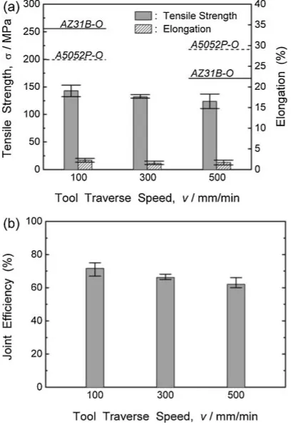
Figure 14 shows the influence of the tool traverse speed on the (a) average ultimate tensile strength and total elongation, and (b) joint efficiency of the TWBs produced under the constant tool rotation speed of 1400 rpm. The broken and solid lines show the average ultimate tensile strength and total elongation of the A5052P-O aluminum alloy and AZ31B-O magnesium alloy plates, respectively. And then, the positive and negative error bars represent the maximum and minimum values, respectively. In all the tool traverse speeds, the TWBs exhibited lower average tensile strength than the base metals. It is noticeable that, in all cases, the average joint efficiency of the TWBs exceeded 62%, and the maximum average tensile strength of about 143 MPa was obtained at 100 mm/min, which was nearly equivalent to the joint efficiency of about 72%. The average tensile strength was slightly decreased with the increase in the tool traverse speed. The average elongation of the TWBs was about 2% or less considerably lower than those of the base metals, without significant changes as a function of the tool traverse speed.
4. Conclusions
In this study, the TWBs of A5052P-O aluminum and AZ31B-O magnesium alloys were produced by the FSW process. And then, the influences of the tool rotation speed and tool traverse speed on surface appearance,
macrostruc-ture and tensile properties of the TWBs were experimentally investigated. The following results were obtained.
(1) The sound surfaces without large defects were success-fully obtained at 1000, 1200 and 1400 rpm under the constant tool traverse speed of 300 mm/min, although, for 800 and 1600 rpm, the large macroscopic defects were formed in the SZ with the rough surface. In addition, also for 100, 300 and 500 mm/min, the sound surfaces without large defects were obtained under the constant tool rotation speed of 1400 rpm. (2) In the range of 1000 to 1400 rpm, the surface roughness was decreased in the SZ with the increase in the tool rotation speed under the constant tool traverse speed of 300 mm/min. In addition, the increase of the tool traverse speed led to the decrease in the surface roughness under the constant tool rotation speed of 1400 rpm. These results show that the tool rotation speed and tool traverse speed are very important parameters in controlling the surface morphology of the SZ. (3) In the SZ, the bonded interface was clearly evident with plastic flow pattern between the aluminum and magnesium alloys, although an onion ring pattern was not formed. (4) During tensile testing, the FSWed TWBs were fractured in the SZ at the early stage of the plastic deformation,i.e.
strain hardening region, without remarkable area reduction near the fracture region.
(5) The TWBs exhibited the similar average tensile strength, showing that there were not noteworthy changes in the tensile Fig. 13 Typical nominal stress-strain curves for the tensile deformation of
the tailor-welded blanks produced at the various tool traverse speeds under the constant tool rotation speed of 1400 rpm. The enlarged curves for the A5052P-O aluminum and AZ31B-O magnesium alloys were also shown for comparison.
[image:6.595.325.529.74.372.2](6) The average total elongation of the TWBs was about 2% or less considerably lower than those of the base metals, without significant changes as functions of the tool traverse speed and the tool traverse speed.
REFERENCES
1) W. M. Thomas and E. D. Nicholas: Mater. Des.18(1997) 269–273. 2) C. J. Dawes and W. M. Thomas: Weld. J.75(1996) 41–45. 3) A. Sanderson, C. S. Punshon and J. D. Russell: Fusion Eng. Des.49–50
(2000) 77–87.
4) I. Shigematsu, Y. J. Kwon, K. Suzuki, T. Imai and N. Saito: J. Mater. Sci. Lett.22(2003) 353–356.
5) I. Shigematsu, K. Suzuki, T. Imai, Y. J. Kwon and N. Saito: J. Mater. Sci.40(2005) 2971–2974.
6) K. N. Krishnan: Mater. Sci. Eng. A327(2002) 246–251.
7) W. B. Lee, Y. M. Yeon and S. B. Jung: Scr. Mater.49(2003) 423–428.
13) W. M. Thomas, D. E. Nicholas, J. C. Needham, M. G. Murch, P. Templesmith and C. J. Dawes: GB Patent Application No. 9125978.8, Dec. 1991, US Patent No. 5460317, Oct. 1995.
14) A. Steuwer, M. J. Peel and P. J. Withers: Mater. Sci. Eng. A441(2006) 187–196.
15) T. Watanabe, H. Takayama and A. Yanagisawa: J. Mater. Proc. Tech. 178(2006) 342–349.
16) A. Scialpi, M. De Giorgi, L. A. C. De Filippis, R. Nobile and F. W. Panella: Mater. Des.29(2008) 928–936.
17) A. Abdollah-Zadeh, T. Saeid and B. Sazgari: J. Alloy. Compd.460 (2008) 535–538.
18) S. Hirano, K. Okamoto, M. Doi, H. Okamura, M. Inagaki and Y. Aono: Quart. J. Jpn. Weld. Soc.21(2003) 539–545.
19) Y. S. Sato, S. H. C. Park, M. Michiuchi and H. Kokawa: Scr. Mater.50 (2004) 1233–1236.
20) J. Yan, Z. Xu, Z. Li, L. Li and S. Yang: Scr. Mater.53(2005) 585–589. 21) S. A. Khodir and T. Shibayanagi: Mater. Trans.48(2007) 2501–2505. 22) T. Morishige, A. Kawaguchi, M. Tsujikawa, M. Hino, T. Hirata and