Evaluating Microstructure and High-Temperature Shear Behavior
of Hot Extruded Al-Al
13Fe
4Nanocomposite
Narguess Nemati
1,2,+and Masoud Emamy
11Center of Excellence for High Performance Materials, School of Metallurgy and Materials Engineering,
College of Engineering, University of Tehran, Tehran, Iran
2Center for Nano-Wear, Yonsei University, Seoul 120-749, Republic of Korea
The microstructure and mechanical properties of extruded aluminum matrix composites reinforced with novel Al13Fe4complex metallic
alloy (CMA) nano-particles were investigated. The large grained structure of the hot pressed matrix was refined after addition of Al13Fe4CMAs,
the effect being more pronounced for Al-5 mass%Al13Fe4composite. The hot pressed specimens were subjected to uniaxial hot extrusion
process (with a 9 : 1 ratio at 400°C). This had a great effect on the microstructural evolution of the composites. High-temperature shear punch test (SPT) was employed to investigate the effects of 110 mass%Al13Fe4additions on the microstructure and mechanical properties of the
as-extruded Al/Al13Fe4composite. The shear behavior of the alloys was investigated in the temperature range of 25350°C. Al-5 mass%Al13Fe4
nanocomposite had the highest shear strength among all the materials tested at high temperature (150, 250 and 350°C), mainly due to the semi-ideal dispersion of the thermally stable Al13Fe4nano-particles, and the refined microstructure of the extruded specimen, which results in
pronounced enhancement in mechanical properties. These thermally resistant particles are believed to increase the resistance of the composite against the applied shear stress in the deformation zone during the subjection of the material to SPT. [doi:10.2320/matertrans.MG201605]
(Received October 7, 2015; Accepted December 11, 2015; Published January 29, 2016)
Keywords: aluminum-based nanocomposite, complex metallic alloys (CMA), high-temperature shear punch test, extrusion, shear strength
1. Introduction
Lightweight aluminum matrix composites (AMCs) con-sisting of a typically insoluble dispersed second phase possess mechanical, physical and tribological properties that are superior to that of the matrix or base material, making them highly suitable as lightweight substituents in the aerospace and automotive industries.14)For different appli-cations, the aforementioned properties of such AMCs can be tuned by varying the ratio, shape, concentration and composition of the second phase materials used.5) For example, Nardone et al. showed that incorporation of 20
30 vol% of SiCp to Al composite enhanced the elastic modulus and yield strength through an Orowan strengthening effect, and increased the dislocation density of the Al matrix, which was attributed to the difference in the coefficient of thermal expansion between SiC and the matrix.6)Common second phase reinforcing agents of AMCs include carbides, oxides,7)nitrides, carbon-based structures (CNT, GO, graph-ite)79) and different intermetallic compounds.4,1014) In particular, SiC and Al2O3 are among the commonly used ceramic reinforcements.1518)Also, recent new generations of intermetallic compounds with extraordinary attributes, such as complex metallic alloys (CMAs), have attracted a lot of interest in being used as reinforcement materials in AMCs and magnesium-based composites.10,1921)
CMAs are light weight intermetallic compounds with hundreds to thousands of atoms per unit cell.20,21) These complex compounds exhibit outstanding mechanical proper-ties, including superior hardness, high strength, low surface energy, and low coefficient of friction in vacuum.20)Because of such advantages, as well as their production cost effectiveness, CMAs are attractive materials to be used as reinforcing agents in various composites.21) It should be
noted that mechanical and tribological properties of CMAs are known to be comparable with some of the recently developed advanced coatings for metals.2224)
Little is known about the mechanical properties of Al-based composite materials reinforced by CMA particles, but some examples exist. For instance, the usage of ¢-Al3Mg2 CMA as a reinforcing agent in Al and Al alloy matri-ces,4,11,12)and the room-temperature dry sliding wear behav-ior of Al matrices reinforced with either AlCuFeB or AlCuFeCr CMAs25,26)have been the subject of a few studies. Nevertheless, for systems of AMCs with a gradient composition of CMAs, there is no previous study that addresses the elevated temperature mechanical behavior, including the elastic modulus, yield strength, ultimate strength and ductility characteristics.
Al13Fe4 CMA is a novel intermetallic compound that has recently attracted a lot of interest. It contains 102 atoms in its monoclinic crystal structure unit, and owes its superior properties to the large number of atoms in its crystal unit.20,27) The single-crystal growth of a large structure of Al13Fe4 CMA is previously reported.27) Plastic deformation and interfacial properties of Al-Al13Fe4 have been discussed for an in-situ composite consisting of Al matrix and Al13Fe4 particles.13,14,28)Also, it has been shown that Al
13Fe4exhibits a high hardness of 815 HV, a density of 3.8 g/cm3, and an estimated surface energy of 2.04 J/m2.20,29) Given such advantages of Al13Fe4, along with economic production methods of the compound, there is a strong interest in utilization of this compound for new application areas, where superior mechanical properties are important, in particular, high temperature properties.27)Thus, the focus of the present work is to investigate the potential of Al13Fe4 intermetallic compound as a reinforcing agent for fabrication of a hard, tough and lightweight AMC with enhanced high temperature mechanical properties, and, also, to acquire an understanding about the involved mechanisms.
+Corresponding author, E-mail: Narguess.Nemati@ut.ac.ir
Special Issue on Frontier Researches Related to Nano/Microstructure, Microstructure Control and Mechanical Properties of Materials
behavior were investigated. Extrusion was performed to induce large plastic deformation, which facilitates manufac-turing of high-strength and lightweight AMCs.
In the majority of previous similar studies, the mechanical properties of AMCs have been assessed using conventional tensile testing method.16,35,36)The tensile strength data can be related to the effective shear strength data obtained through the shear punch testing (SPT) method on thin specimens for a variety of materials.34)SPT is a miniature testing technique, which is based on blanking operation for evaluating mechanical properties.37) In the case of metals, a close correlation between SPT and tensile test data has been properly identified. Thus, SPT is a reliable method to evaluate the flow properties, especially when only a small amount of material is available. Therefore, in the present work, SPT is used for evaluation of high temperature mechanical properties of the systems studied.
2. Experimental
2.1 Material and methods
Based on the binary phase diagram of Fe and Al,29) an appropriate composition of 2324 at%Fe was chosen. Then, using pure elemental Fe and Al materials and utilizing an inductive furnace for precise casting technique, a pre-alloyed ingot of Al13Fe4was prepared. In the second step, milling of the pre-alloyed intermetallic compound was carried out using a two-cup planetary ball-mill. Details of mechanical alloying and milling parameters are explained elsewhere.3,4)
Utilizing mechanical alloying (M/A) technique, various fractions (0, 1, 3, 5, 7 and 10 mass%) of nano-sized Al13Fe4 particles were added to pure atomized Al (150 µm in size and 99.98%purity) matrix powder, under conditions discussed in our previous work.3,4)The aim was to determine the optimum level of reinforcement yielding the best mechanical proper-ties. Thus, the powder mixture was hot pressed at a pressure of 650 MPa at 450°C for 30 min under the flow of Ar gas. Thus, specimen with different amounts of Al13Fe4 particles were prepared. In the next step, in order to degas the hot pressed compacts, they were heated at a constant rate of 10°C per minute up to 120°C in a vacuum of 10¹3Pa for 3 h. Thus, the absorbed gasses were removed prior to the extrusion process. Then, a hot extrusion process was applied to remove the pores and refine the microstructure of the grains. For the extrusion process, reduction ratios of 9 : 1 and 11 : 1 were used at a ram speed of 3.2 mm/s. The extruded parts were cut
to a size of 10©10©1 mm3. Then, the specimens were ground and polished to obtain an average surface roughness of³0.1 µm.
To compare the relative densities of the consolidated specimens before and after extrusion, the theoretical and experimental density values (based on Archimedes’principle) were calculated. For each specimen, the Vickers microhard-ness was determined using a hardmicrohard-ness tester (Zwick/Roell ZHµ, Indentec). A load of 1 kgf and a dwell time of 10 s were used for the VHN measurements. The Young’s modulus and nanohardness measurements were made with a nanoindenter (CSM, UNHT) using a Berkovich diamond tip (R<100 nm). In order to assess the properties with respect to depth, the continuous depth-sensing indentation technique was em-ployed.38)Calculation of the indentation hardness was based on the Oliver-Pharr method.39,40)
2.2 Shear strength measurements
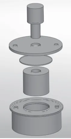
The 1-mm thick specimens (various mass% of Al13Fe4 reinforced Al composites) were initially ground to a thickness of 0.7 mm. In the next step, using a shear punchfixture with a 3.175 mm diameter flat cylindrical punch and 3.225 mm diameter receiving-hole, cubic sections of 10 mm©10 mm in area were punched for the SPT (Fig. 1 shows the schematic picture of the SPT die and setup). The punch displacement was normalized to the specimen initial thickness in order to remove the gage tolerance. Three tests were performed on different specimens of the same composite for each temper-ature, and the average values were reported.
Using a screw driven SANTAM material testing system, shear punch tests were carried out in the temperature range of 25350°C. For these experiments, a load cell of 20 kN capacity and a crosshead speed of 0.25 mm/min were used. After application of the load, the applied load (P) was measured automatically through a computer as a function of punch displacement. The shear stress of the tested materials (¸) was determined using the following relationship (1).41)
[image:2.595.368.486.71.302.2]¸¼³p
dt ð1Þ
wherePis the punch load,tis the specimen thickness andd
is the arithmetic average of the punch and die diameters. Three different samples were tested for each condition, and it was observed that the variation in the values of the measured ultimate shear strength (USS) was small. It should be noted that before and after testing, the specimens were ultrasoni-cally cleaned.
2.3 Characterization and observation of morphology
Detailed microstructural studies were carried out using a scanning electron microscope (SEM; JEOL 6210) that was equipped with an energy-dispersive X-ray spectroscopy (EDS; OXFORD INCA Energy), a field-emission scanning electron microscope (FESEM; JEOL-7001F), and a trans-mission electron microscope (TEM; PEM-125 Kev) with a 0.2 nm point-to-point resolution operating at 60 kV and capable of selected-area diffraction (SAD) analysis.
Structural characterization was performed using an X-ray diffraction (XRD) equipment (Philips) with a Cu K¡radiation source (=0.15405 nm) at 40 kV and 30 mA. The 2ª step size was 0.02°, and the dwell time per step was 5 s.
In order to study the ultra-fine grained structure of the cross section of extruded nanocomposite specimen, an ultra-high resolution spherical aberration correction scanning transmission electron microscope (STEM; JEOL-JEM ARM200F) was used. For preparation of cross sectional TEM membranes with a thickness of 0.5 µm, a Focused Ion Beam (FIB; JEOL-JIB 4601F) system was used. Surface analysis of the sheared punched area, were accurately measured using SEM.
3. Results and Discussion
3.1 Microstructural evolution
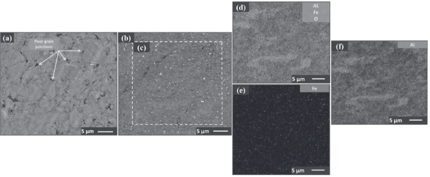
Figure 2(a) and (b) depict the SEM images of micro-structures of the surfaces of hot pressed and as-extruded specimens containing 5 mass% of second phase Al13Fe4
nanoparticles. As can be seen, although grain growth was noticeably hindered by the hard reinforcing nanoparticles, which prevented boundary movement at the time of sintering, some pores still exist and once the composites were subjected to a subsequent extrusion process a semi-full density was obtained (arrows in Fig. 2(a) indicate the pores remained after application of the hot press process). To observe the quality of distribution of the second phase through the matrix right after the extrusion, chemical analysis of a selected area of the surface of the as-extruded sample was done. EDX mapping provides a meaningful picture of the elemental distribution of as-extruded surface of Al-5 mass%of Al13Fe4. Figures 2(c)(f ) depict the results of EDX measurements. As can be seen, a uniform distribution of iron containing phase is observed through the matrix after application of a uniaxial extrusion process.
Relative density of the composite specimens before and after extrusion with respect to mass% of Al13Fe4 were measured and reported elsewhere.42) It was evident that application of extrusion with a ratio of 9 : 1 was very effective in inducing pore closure, and, therefore, could assist in producing a dense structure. Measured values verified the microstructural analysis in Fig. 2 and also showed that for extruded specimens the relative density values were sub-stantially higher (0.910.99) and, in particular, for the composite containing Al-5 mass% of Al13Fe4 the density turned out to be 0.99.
In order to see the simultaneous effects of reinforcing agent weight percentage (i.e., weight percentage of Al13Fe4 nanoparticles), and application of hot extrusion process on the homogeneity, second phase distribution and refinement effect on the microstructure of the composite, a closer inspection of the grains and morphology of the hot pressed and the as-extruded specimens were carried out. Thus, bright
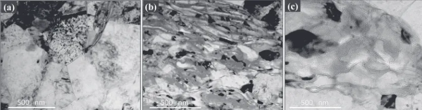
field TEM images were made from the cross section of the hot pressed nanocomposite reinforced with 5 mass% Al13Fe4 (Fig. 3(a)) and as-extruded nanocomposite reinforced with 5 and 7 mass% Al13Fe4 (Fig. 3(b) and Fig. 3(c), respectively). The following observations were made. First, in line with our previous studies, the as-extruded composites showed much
Fig. 2 Microstructures of the surface of the Al-5 mass%Al13Fe4nanocomposite specimen (a) hot pressed, (b) as-extruded with ratio of
[image:3.595.81.518.70.250.2]smaller grain sizes (50100 nm; Fig. 3(b)) compared to the milled and hot pressed composite specimens (0.51 µm; Fig. 3(a)). Second, the grains of the as-extruded composites containing 5 mass% and 7 mass% All3Fe4 appear to be different in size and morphology. Although addition of Al13Fe4CMA nanoparticles as afine-scaled phase could pin the grain boundary and prevent the migration of grain boundaries, the difference in the amounts of Al13Fe4 CMA nanoparticles in these two as-extruded composites (passing optimum level of 5 mass%) caused poor distribution of the second phase throughout the matrix (Fig. 3(c)). Third, the grain boundaries in the hot pressed specimen are sharp (Fig. 3(a)), whereas many of those in the extruded compo-sites are curved and poorly defined (Figs. 3(b)(c). This observation indicates that full dynamic recrystallization (DRX) has occurred in the hot pressed composite during sintering, while this has not happened in the two as-extruded composites after the same processing conditions. The retardation of DRX in the as-extruded composites could be attributed to the presence of a high density of fine particles formed as a result of the breakdown of the reinforcement particulates or the possible existence of a surface oxidefilm on the powder during the extrusion process.8) In contrast to the typical coarse and equiaxed crystalline microstructure of the hot pressed specimen (Fig. 3(a)), the elongated subgrain structure of the adjacent grains in Fig. 3(b) and Fig. 3(c) was attributed to the existence of large subsurface strains induced during the uniaxial extrusion process. Moreover, orientation of subgrains clearly demonstrates that they were elongated in extrusion direction. Also, upon extrusion, the quality of the grain junctions was considerably improved and the reinforc-ing material appeared to be rather uniform (see adjacent dark and light grains of pure Al and composite Al/Fe grains in the TEM image of Fig. 3(b)).
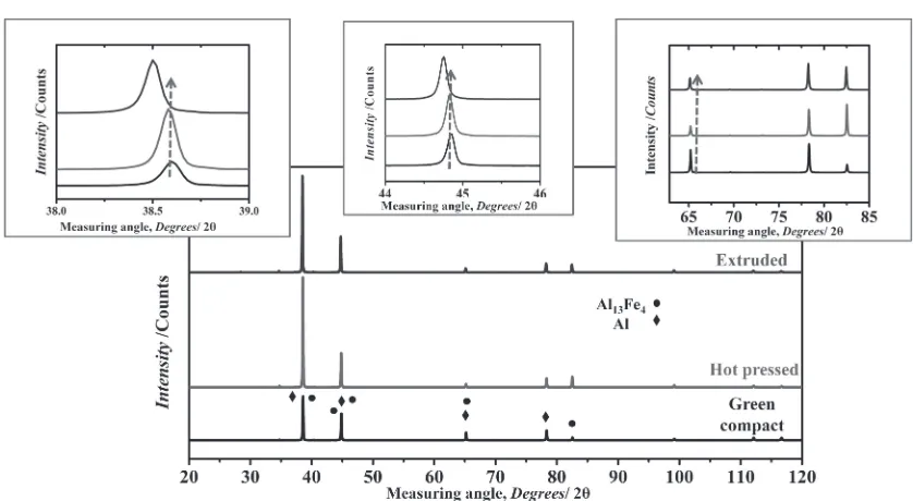
In order to investigate whether phase transformation has occurred in hot pressed and as-extruded composites, X-ray diffraction (XRD) analysis was carried out on selected specimens to identify the existing phases. Figure 4 presents the XRD patterns of the green compact, hot pressed and extruded specimens of Al-5 mass%Al13Fe4 nanocomposite, which enables one to determine the phases present in each material. In Fig. 4, the observed peak intensities are successfully indexed as reflections of ¡-Al and the Al13Fe4 intermetallic compound. Thus, the absence of un-indexed diffraction peaks suggests that, beside the parent¡-Al phase, Al13Fe4is the only phase present in the prepared compound.
It should be noted that because of the close proximity of some of the weaker diffraction peaks of Al13Fe4 and ¡-Al phases, accurate identification and quantification of such XRD peak intensities turned out to be an impossible task.
In the XRD pattern of the extruded specimen, (~6 2 3), (0 2 5) and (4 2 3) reflections are identified as the most intense peaks (Fig. 4). This XRD pattern is matched with the JCPDS Card No. 00-029-0042 reference code of Al13Fe4 intermetallic compound with monoclinic structure. Inspection of the XRD pattern of the green compact, hot pressed and as-extruded specimens clearly revealed that, upon application of thermomechanical treatments on the green compacts, peak shifts and peak broadenings have happened, which are clear indications of the occurrence of lattice parameter alteration. The magnified insets clearly demonstrate the significant broadenings and the distinguishable shifts of the peaks, which occurred due to the application of a large amount of strain, as discussed in a previous study.4) The lattice parameters of the green compact, hot pressed and as-extruded specimen were calculated by NelsonRiley method.43) Results of this analysis revealed that, due to the application of thermomechanical treatment, the lattice parameter has increased from a value of 1.140 nm (for the green compact) to a value of 1.250 nm (for the extruded specimen). This increase (about 10%) in the value of the lattice parameter could be attributed to the diffusion of Fe atoms into the crystal structure of ¡-Al during the milling and subsequent hot extrusion processes, which led to the expansion of crystal structure. This is in line with the previous reports that the peak shift to lower angles in Al-Fe systems, indicates the dissolution of Fe atoms into the¡-Al phase.44)
It was also reported previously that, even after application of a long milling process, Fe atoms cannot be completely dissolved into the Al matrix at any composition of the AlFe alloy powder.45) This could be attributed to the fact that, thermodynamically, solid solubility cannot be significantly extended by adding more Fe content after the Fe atoms reached maximum equilibrium solubility in the Al matrix during MA.28)
[image:4.595.89.506.72.181.2]process®a uniform Al-Al13Fe4 composition was achieved after extrusion.
3.2 Mechanical properties 3.2.1 Hardness measurement
Results of microhardness measurements obtained for the bulk aluminum matrix and the nanocomposite specimens before and after extrusion are reported in our previous study.42) Measured values are in the approximate ranges of 0.381.55 GPa and 0.782.1 GPa for hot pressed and as-extrude specimens, respectively. A complimentary set of micro- and nanohardness measurements were carried out to compare the nanohardness and microhardness values for hot pressed and as-extruded specimens (see Fig. 5). These results have verified the previous measurements. High load nano-indentation tests of the hot pressed and as-extruded speci-mens were carried out to measure the possible interfacial failure load, as well as to acquire data regarding the load
bearing capacity of different elements present on the surfaces of the specimens. The latter understanding was achieved through applying indentations believed to be close to the reinforcement material, matrix material and reinforcement-matrix interface. It should be noted that compared to microhardness data, the scatter of nanohardness data is larger. This can be attributed to the fact that in nanohardness measurements a measured value is dependent on the microscopic position of the indentation spot. More specifi -cally, for an individual specimen, an indentation site could be positioned on hard nanoparticles of Al13Fe4CMA embedded beneath the surface, a soft matrix spot, or at a location precisely on or near to the reinforcement-matrix interface. Based on the data shown in Fig. 5, by increasing the content of the reinforcing agent, the values of micro- and nanohard-nessfirst increased, reached maxima at a reinforcement agent concentration of 5 mass%, and then decreased. This is in line with the fact that incorporation of hard particles in the ductile metal matrix material improves the overall properties of the composite material once a high level of bonding quality between the reinforcement and matrix, a low degree of porosity, and a good distribution of reinforcing particles are achieved.4648)
For as-extruded specimens, due to application of a severe plastic deformation, the hardness values (both micro- and nanohardness) were substantially enhanced. This is in line with this belief that the existence of a strong particle-matrix interface along the dislocation motion barriers would cause a better resistance to indentation during high load nano-indentation. In order to provide the proof of the above-mentioned assumption, a closer inspection was made of the area under the indentation spot of a typical composite of Al-mass% of Al13Fe4, which is explained in detail in the following paragraph.
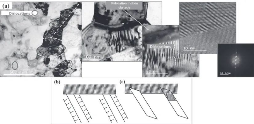
Figure 6(a) shows high resolution brightfield TEM images of the as-extruded 5 mass% reinforced nanocomposite, and the corresponding magnified insets and selected area
Fig. 4 XRD patterns of the green compact, hot pressed and as-extruded specimens of Al-5 mass%Al13Fe4nanocomposite. Insets show the
enlarged 2ªdegree range of measurements.
Fig. 5 Variation of microhardness and nanohardness values versus composition of Al13Fe4 before and after extrusion (the measured date
[image:5.595.88.507.63.293.2] [image:5.595.65.270.345.495.2]diffraction pattern (SADP) of the image. As can be seen, in certain areas dislocation motion was inhibited. This is in line with previous studies indicating that hard intermetallic nanoparticles, or formed oxide layers, serve as obstacles to dislocation motion within a matrix. Interestingly, what was observed in our images was in line with the dislocation motion mechanism proposed by Fine and Ritchie (1979),49) which is based on the idea of dislocation pile-ups (Fig. 6(b) and Fig. 6(c)). In this mechanism, a surface obstacle, commonly an oxide layer or a particle, is envisaged to stop movements of dislocations resulting in pile-ups along slip bands. Beyond a critical size of the pile-ups, the barrier breaks down resulting in an avalanche dislocations, which gives rise to intrusion or extrusion formation (Fig. 6(b) and Fig. 6(c)) depending on the sign of dislocations.49,50) It should also be mentioned that a reduced interparticle distance between nanoparticle reinforcements results in enhancement of the Orowan mechanism up to optimum level of reinforce-ment agent content.5,35) Lastly, the clear facets of the dark intermetallic phase in the ¡-Al grains indicate a coherence interface between Al13Fe4 and the ¡-Al grains during extrusion. Alternatively, the observation of clear facets may indicate that the strain exerted by extrusion is not sufficient for complete integration of the particles and matrix.
Finally, it should be mentioned that a considerable load-bearing effect against the pressure applied by the nano-indenter was observed for composites, and the microhardness measurement results were also consistent with the nanohard-ness values.
3.3 Strength, shear and ductility behaviors
Strength, shear and ductility behaviors of the composites and matrix were investigated by means of SPT in the temperature range of 25350°C. Three tests were performed on different specimens of the same composite for each temperature, and the average values were reported. Interest-ingly, the results of each three sets of tests showed excellent reproducibility of SPT data in terms of USS and SYS values
for these composites, e.g., see Fig. 7 for the results of Al-5 mass% Al13Fe4 composite at 25°C. This suggests that a refined semi defect-free microstructure were obtained, which can be attributed to the relatively high extrusion ratio, and, also, application of the uniaxial press-sinter method. There-fore, SPT turned out to be a useful tool for investigating the mechanical properties of the present extruded specimens.
3.3.1 Strength behavior
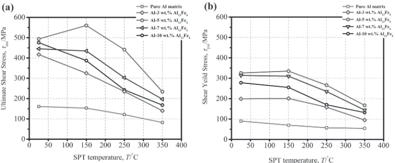
SPT curves of the studied composites obtained at 25 and 150°C are shown in Fig. 8(a) and (b), respectively. In both cases, the Al-3 mass% Al13Fe4 composite has the lowest strength and the Al-5 mass%Al13Fe4 composite exhibits the highest one. Also, it was observed that as the test temperature rose up to 150°C, lower SYS and USS values were obtained in comparison to the room temperature condition results, except for the Al-5 mass%Al13Fe4composite, which showed USS values of 560 MPa (at 150°C) and 495 MPa (in 25°C). To have an overall view on the variation of strength with temperature, the USS and SYS data are summarized in Fig. 9(a) and (b), respectively. From the data, one can conclude that not only the extrusion process, but also
Fig. 6 (a) High resolution brightfield TEM images of the as-extruded Al-5 mass%Al13Fe4composite, and the corresponding magnified
insets and SADP of the selected area of the image. Dislocation motion mechanism proposed by Fine and Ritchie (1979),49)based on the
idea of dislocation pile-ups (b) intrusion and (c) extrusion formation.
Fig. 7 Results of three similar SPT test (curves) for Al-5 mass%Al13Fe4
[image:6.595.92.505.70.271.2] [image:6.595.335.519.336.483.2]addition of reinforcing agent (Al13Fe4 nanoparticles) up to 5 mass% has pronouncedly improved the shear strength of the base pure Al matrix at elevated temperatures. In particular, it is noteworthy that even addition of 3 mass% of Al13Fe4nanoparticles could significantly enhance the shear strength of the material, which is attributed to the presence of the hard and high temperature resistant intermetallic phase. Since it was proved by SEM and TEM (Fig. 2 and 3) that there is a random distribution of the Al13Fe4 second-phase particles with distinguishableflow pattern, these particles can perhaps maintain their stability and strength at high temper-atures, resisting the applied shear stresses in the deformation zone at high temperatures, and thus increase the overall shear strength of the material.
In order to gain an insight into the reason of the increased strength of the composite materials at high temperatures, giving an overall view about the possible strengthening mechanisms and their role in the current system would be useful. Among strengthening mechanisms, solid solution strengthening effects usually disappear at high temperatures, which is due to the high diffusion rate of Fe in Al.44)Also, reduction in SFE of Al matrix (initially 160200 mJ m¹2) has little effect at high temperatures, because of increased dislocation mobility at elevated temperature.51) Besides, negligible difference in coefficient of thermal expansion (CTE) between Al and dispersed second phase particles of
Al13Fe4 (both values are estimated to be 1112©10¹6 per degree centigrade in the temperature range of 50150°C)45,52) eliminates the strong probability of dislocation generation caused by CTE mismatch.45) Thus, an excellent agreement has been achieved with the assumptions and experimental results in explaining the strengthening phenomenon at elevated temperatures due to the existence of reinforcement, which is explained in the following paragraph.
Al13Fe4particles have rather high thermal stability because of their high melting point (³1160°C) and hardness of 800 Vickers, thus tend to resist shear stress at above 0.5Tmof the composite specimen (300°C). Hence these hard particles21) with high thermal stability are mainly responsible for the higher strength of the composite containing Al13Fe4at high temperatures. Also, the fact that nanoparticles pose obstacles to dislocation motion (Fig. 6), in particular for the optimum dispersion of 5 mass%, could be considered as another reason for exhibiting such mechanical improvement, especially at room temperature.
Thus, maintaining the low volume fraction of the reinforcing nanoparticles to 5 mass% is thought to be essential to attain an ultrahigh strength of 500 MPa at 150°C. This conclusion is reasonable considering the fact that heat resistant nature of this composite stems mainly from the microstructure stability of the Al13Fe4 intermetallic com-pound owing to the sluggish diffusivity of Fe in Al. Because
Fig. 8 Shear stress with respect to normalized displacement for various composite specimens at (a) Rt and (b) 150°C.
[image:7.595.100.497.66.228.2] [image:7.595.99.498.271.436.2]the coarse grains are pure Al, they are unstable at elevated temperatures.
3.3.2 Shear behavior
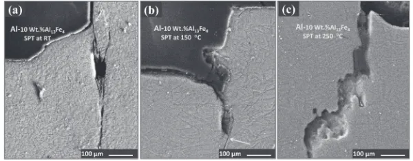
In order to investigate the shear deformation evolution of the composites, shear punch tests were stopped at various stages of deformation, and the cross-sections adjacent to and beneath the punch spot were examined by SEM. These examinations were made at both room temperature and elevated temperatures for various composites and the matrix. The results are presented in Fig. 10 and Fig. 11, where fracture surfaces of Al-5 mass% Al13Fe4 and Al-10 mass% Al13Fe4 tested at various temperatures are shown, respec-tively.
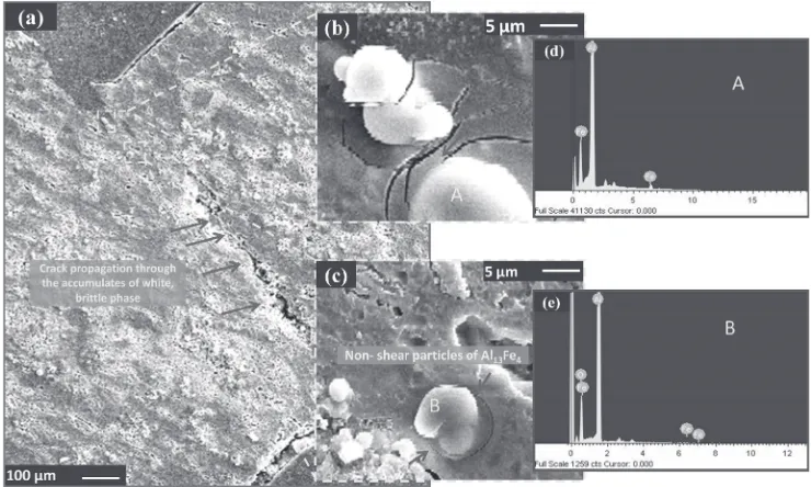
In Fig. 10 and Fig. 11, an interesting feature is the fracture mode of the composite specimen. In general, SPT fracture failure could occur either by micro-void formation and coalescence or by macro-crack growth. Comparing the macrostructures of the composite after low temperature (25°C) and high temperature (150°C) deformation, it is clear that limited deformation has occurred at room temperature. As can be seen in Figs. 10 and 11, for both room and 150°C temperatures, crack initiation has been started from the punch-die-specimen interface. For such cases, it has been suggested that the sum of the incremental work of cracking and plasticflow over the reduced volume in front of the crack is less than the incremental work of flow without cracking over the net section. Therefore, it is concluded that fracture of the particles of second phase has had negligible effect on the fracture mode of the pure Al matrix. Figure 12(a) and magnified insets (Figs. 12(b)(c)), show the SEM image of a typical fractures area of Al-7 mass% Al13Fe4 composite, which was subjected to SPT at 250°C. As can be seen from the magnified insets, crack initiation sites were exactly from
the location of agglomerates of reinforcing agent (white phases). Interestingly, the magnified insets clearly reveal that passage of the cracks through the agglomerates of the intermetallic is inhibited and the crack has bypassed the hard phase and continued to propagate from the particles circum-ference in the soft matrix. Figures 12(e) and (f ) show the EDX point analysis of the white phase particles and it clearly reveals the presence of Al and Fe in the agglomerates, which provides sufficient proof for the notion that agglomerates are the clusters of non-shear Al13Fe4intermetallic compound.
3.3.3 Ductility behavior
At room temperature, the material has quite low ductility, which induced a fast crack growth stage, causing the load to drop suddenly after the maximum load (Fig. 10(a)), and making it impossible to stop the test before specimen fracture. From Figs. 10 and 11, it is also inferred that in SPT the plastic deformation of the material is a through-thickness process, which covers the whole through-thickness of the specimen, and is restricted to a confined sheared region with no evidence of plastic deformation outside this region. By approximating the width of this region to be close to the width of the clearance between the die and the punch (i.e., 25 µm), the deforming volume is calculated to be ³1.9© 10¹1mm3, which is much larger than the value of 3.5© 10¹4mm3, usually observed in a microhardness test.32)This significantly higher volume of the deformation zone suggests that the results of SPT experiments are less affected by the inhomogeneity of the material.
[image:8.595.119.480.69.192.2]The observed substantial deformation (elongation ³60 70%) of the Al-3 mass% Al13Fe4 composite specimen at 25°C and 150°C (Figs. 8(a) and (b)) could be due to the possible softening of the Al matrix, meaning that the fact that only a little amount of reinforcing agent is present in the
Fig. 11 SEM images of cross-sections adjacent to and beneath the punch area for shear punched Al-10 mass%Al13Fe4composite at (a) Rt,
[image:8.595.148.448.235.352.2]matrix of the composite has made the soft Al matrix as the dominant decisive factor in the deformation zone. In this regard, the SPT leads to the weakening of the deforming regions adjacent to the punch, and thus, to the reduction of the shear strength. It is worthy to note that, for all compositions of the specimens of the present systems, passing 150°C, the softening of the matrix is more dominant in shear behavior in comparison to the role of the hard, thermal resistant dispersed intermetallic. Matrix does not have sufficient thermal stability to resist plastic deformation at high temperatures. One can conclude that the presence of the coarse ¡-Al grains causes the degradation of the high temperature strength. However, in case of Al-10 mass% Al13Fe4 composite specimen (Fig. 11(c)), the high surface energy leads to the formation of clusters of nanoparticles. The presence of these clusters (Fig. 5) is not effective in hindering the movement of dislocations, and can hardly generate a physico-chemical bonding to the matrix, thus significantly reducing the strengthening capability and the limits of the ductility of the composite.53) According to the explained observations, the reasonable ductility of specimens in the whole range of the testing temperature could be first attributed to the lack of brittleness of the composites. In other word, the volume fraction of the hard and brittle phase (Al13Fe4) remained lower than the critical amount to cause pure brittleness in cleavage fracture mode of the specimen.
4. Conclusions
The microstructure, hardness and high temperature me-chanical properties of Al-based composite reinforced with Al13Fe4CMA nanoparticles were investigated. Based on the experimental results, the following conclusions are drawn.
(1) The microstructure of hot pressed and as-extruded Al-based composite containing various mass% Al13Fe4
were significantly different. Upon application of a uniaxial extrusion with a ratio of 9 : 1, smaller grain sizes, considerably improved quality of the junctions, much higher relative density (9299%) and rather uniform distribution of the reinforcing material were attained, in particular, for the case of the optimum level of the reinforcement (5 mass%).
(2) Extrusion markedly enhanced the hardness of the press-sintered nanocomposites. The microhardness measure-ments revealed that for Al-5 mass% Al13Fe4, hardness value turned out to be 1.85 GPa. For nanohardness measurements, the average nanohardness value of the various indentations turned out to be 2.1 GPa.
(3) The mechanical resistance of specimens reinforced with the optimum level of Al13Fe4 nanoparticles (5 mass%) was remarkably enhanced relative to that of the pure nanocrystalline Al matrix. At 150°C, the ultimate shear stress increased up to 560 MPa, which is 7 folds greater than pure Al matrix specimen.
(4) The superior mechanical properties of the nanocompo-sites were attributed to the strengthening nature of the thermally resistant and hard reinforcing agent, resulting in an enhanced ductility at the whole range of the test temperatures. At 150°C, the yield and ultimate strength of the composites were the highest and found to be 330 and 560 MPa respectively.
Acknowledgments
[image:9.595.113.483.71.293.2]The authors gratefully acknowledge University of Tehran for the use of laboratory facilities. This work was supported by the National Research Foundation of Korea (NRF) grant funded by the Korea government (MSIP) (No. 2010-0018289). The authors also would like to thank Dr. O. Penkov for performing the hardness measurements.
Fig. 12 (a) SEM image of the punched area of the Al-7 mass%Al13Fe4specimen shear punched at Rt, (b) magnified area of crack
initiating from the location of an agglomerates of Al13Fe4and (c) magnified area of crack bypassing the agglomerates of Al13Fe4, (arrows
fi
Grinkevych, A. V. Sameljuk and I. V. Tkachenko:Wear319(2014) 84 95.
11) S. Scudino, G. Liu, M. Sakaliyska, K. B. Surreddi and J. Eckert:Acta Mater.57(2009) 45294538.
12) A. Zolriasatein, R. A. Khosroshahi, M. Emami and N. Nemati:Int. J. Miner. Metall. Mater.20(2013) 290.
13) S. Miyazaki, A. Kawachi, S. Kumai and A. Sato:Mater. Sci. Eng. A
400401(2005) 294299.
14) N. Yoneyama, K. Mizoguchi, S. Kumai, A. Sato and M. Kiritani: Mater. Sci. Eng. A350(2003) 117124.
15) F. A. Mohamed, K.-T. Park and E. J. Lavernia:Mater. Sci. Eng. A150
(1992) 2135.
16) S. Tahamtan, A. Halvaee, M. Emamy, Z. Y. Jiang and A. Fadavi Boostani:Mater. Sci. Eng. A619(2014) 190198.
17) N. Parvin, R. Assadifard, P. Safarzadeh, S. Sheibani and P. Marashi: Mater. Sci. Eng. A492(2008) 134140.
18) R. Rahmani Fard and F. Akhlaghi:J. Mater. Process. Technol.187188
(2007) 433436.
19) J. Bonneville, G. Laplanche, A. Joulain, V. Gauthier-Brunet and S. Dubois:J. Phys. Conf. Ser.240(2010) 012013.
20) J.-M. Dubois and E. Belin-Ferré: Metallurgy of Complex Metallic Alloys, (Wiley, 2010).
21) J.-M. Dubois, E. Belin-Ferre and K. Urban:Complex Metallic Alloys: Fundamentals and Applications, (Wiley, 2011).
22) S.-S. Yoo and D.-E. Kim:Int. J. Precis. Eng. Manuf.15(2014) 867 873.
23) M.-S. Won, A. Amanov, H.-J. Kim, W.-S. Yun, W.-G. Joo and D.-E. Kim:Tribol. Int.73(2014) 95100.
24) A. Madhankumar, E. Thangavel, S. Ramakrishna, I. B. Obot, H. C. Jung, K. S. Shin, Z. M. Gasem, H. Kim and D.-E. Kim:RSC Adv.4
(2014) 24272.
25) N. Diomidis, N. Göçkan, P. Ponthiaux, F. Wenger and J.-P. Celis: Intermetallics17(2009) 930937.
Eng. A606(2014) 92100.
36) S. Tahamtan, M. Emamy and A. Halvaee: J. Compos. Mater.18(2013) 33313346.
37) ASTM B557: Tension Testing Wrought and Cast Aluminum and Magnesium-Alloy Products,552.
38) O. V. Penkov, V. E. Pukha, A. Y. Devizenko, H.-J. Kim and D.-E. Kim: Nano Lett.14(2014) 25362540.
39) C. Oliver and M. Pharr:J. Mater. Res.19(2004) 320. 40) C. Oliver and M. Pharr:J. Mater. Res.7(1992) 15641583. 41) R. Guduru: Ph.D Thesis, North Carolina State University, (2006). 42) N. Nemati, M. Emamy, O. V. Penkov, J. Kim and D. Kim:Mater. Des.
90(2016) 532544.
43) A. Zolriasatein and A. Shokuhfar:Mater. Des.75(2015) 1723. 44) T. T. Sasaki, T. Ohkubo and K. Hono:Acta Mater.57(2009) 3529
3538.
45) J. Lee, S. Kang, T. Sato, H. Tezuka and A. Kamio:Mater. Trans.43
(2002) 24872493.
46) N. Parvin, R. Assadifard, P. Safarzadeh, S. Sheibani and P. Marashi: Mater. Sci. Eng. A492(2008) 134140.
47) M. Moazami-Goudarzi and F. Akhlaghi:Powder Technol.245(2013) 126133.
48) S. Pournaderi, S. Mahdavi and F. Akhlaghi: Powder Technol. 229
(2012) 276284.
49) M. N. Shetty: Dislocation and Mechanical Behaviour of Materilas, New Delhi, Asoke K. Ghosh, PHI Learning Private Limited, (2013). 50) J. Chen, R. Lengsdorf, H. Henein, D. M. Herlach, U. Dahlborg and M.
Calvo-Dahlborg:J. Alloys Compd.556(2013) 243251.
51) A. K. Vasudevan and R. D. Doherty:Aluminium Alloys-Contemporary Research and Applications, vol. 26, no. 3, (Elsevier Science, 2012). 52) M. Taya and R. j. Arsenault: Metal Matrix Composites, Thermo