Recent Developments in the Application of Surface Mechanical Attrition Treatments
for Improved Gradient Structures: Processing Parameters and Surface Reactivity
Thierry Grosdidier
1,2,+and Marc Novelli
1,21Laboratoire d’Etude des Microstructures et de Mécanique des Matériaux (LEM3 UMR 7239), Université de Lorraine,
7 rue Félix Savart, BP 15082, Metz F-57073, France
2Laboratory of Excellence on Design of Alloy Metals for Low-Mass Structures (DAMAS), Université de Lorraine, Metz F-57045, France
After a short recall of various techniques that use shots to induce surface severe plastic deformation and a brief survey of the advantages of having a gradient structure for mechanical properties, this manuscript presents recent developments taking advantages of the“reactivity”of these modified surfaces in thefields of corrosion,“duplex”surface treatments as well as potential applications for an easier activation of H-storage materials. The importance of controlling the processing parameters (including temperature) to get the optimum gradient structure depending on the desired applications as well as the necessary requirements for a high quality microstructure and chemical characterizations are also highlighted. [doi:10.2320/matertrans.MF201929]
(Received February 21, 2019; Accepted April 16, 2019; Published June 25, 2019)
Keywords: shot peening (SP), surface mechanical attrition treatment (SMAT), ultrasonic shot peening (USP), gradient structure, surface reactivity, surface activation, cryogenic treatment
1. Introduction
Nanocrystalline (NC) materials, generally associated by metallurgists to materials having an average grain size lower than 100 nm, have been receiving increasing attention in the last two or three decades essentially because they possess superior mechanical resistance than their conventional coarse grained (CG) counterparts, but also because of potential applications in a wide variety of technological areas such as corrosion resistance, catalysis, biotechnology, etc+.14)
Methods for processing NC or ultra fine grain (UFG) materials (i.e. having a sub-micrometric grain size) are generally divided into two different categories: (i) those using a bottom-up approach in which nanostructured medias (condensed powders, ball-milled powders, ..) are consoli-dated in bulk forms and (ii) those using a top-down approach in which the microstructure of a bulk sample is refined, essentially using severe plastic deformation (SPD).14)Even if suitable to many industrial applications, the consolidation of nanoscale precursors often leads to contamination (oxidation for example) or residual porosity in thefinal bulk product that are hard to control and may be, in some cases, detrimental. Thus, several processes have been developed to produce materials with UFG, using the top-down approach, through SPD. Some of them, for example the High Pressure Torsion (HPT),5)Equal Channel Angular Pressing (ECAP),6)
High Pressure Sliding (HPS),7) Accumulative Roll Bonding
(ARB),8,9) High Pressure Tube Twisting,10) Linear Flow
Splitting11) or Plastic Flow Machining (PFM)12) are applied on the bulk material to generate fine sub-micrometric microstructures within the components. Because of the load required to deform the parts containing a bulk refined microstructure and the associated reduction in ductility, some of these techniques can be however rather difficult to implement in industry.
On the other hand, as failure is often initiated from the surface, surface treatments focusing on the deformation of
the outer part of a work piece have been developed. These include techniques for which the severe deformation is imparted to the surface either (i) directly, by mechanical shocks,1318) continuous contact1921) or (ii) indirectly, by using pulsed laser22)as well as pulsed ion or electron beam treatments.2326) Some specific zones or critical parts of
components that can be subjected to high stress field, stress concentration, friction or corrosive environment can then be treated locally to enhance their performances. The amount of literature about processes using mechanical surface SPD techniques and their effects on properties has been increasing sharply over the last decade. In particular, the grain refinement mechanisms of the microstructure at the surface and the formation of a gradient microstructure - from NC at the top surface to CG towards the bulk - has been heavily documented now for a wide variety of different metals and alloys together with their effects on mechanical properties such as hardness, strength, fatigue and tribological properties. These different aspects have been reviewed in several manuscripts.2729) Thus, the goal of this short
manuscript is not to give a full view - that would necessarily be incomplete and one-sided - on this field but, more, to highlight some more recent findings and trends that are believed to have a potential for improving further the material properties and gain further applications. Therefore, after a short recall of various techniques - derived from the shot peening (SP) - which use shots to induce severe plastic deformation at the surface and a brief survey of the advantages of having a gradient structure for mechanical properties, this manuscript will highlight the potential interest of modifying the temperature of the shot peening treatment as an additional processing parameter for improving further the microstructure and mechanical proper-ties. Also, as the plastically deformed surface is more
“reactive”, recent development and applications of the modifications of surface reactivity in the fields of (i) corrosion, (ii) duplex surface treatments and (iii) H-storage materials will be highlighted.
+Corresponding author, E-mail: thierry.grosdidier@univ-lorraine.fr
Special Issue on Severe Plastic Deformation for Nanomaterials with Advanced Functionality
2. Shot Peening and Derived Techniques of Surface Severe Plastic Deformation Techniques
According to references cited in a recent review on laser shock peening and mechanical shot peening by Shukla
et al.,30)objects dating back to 2700 BC such as weapons and
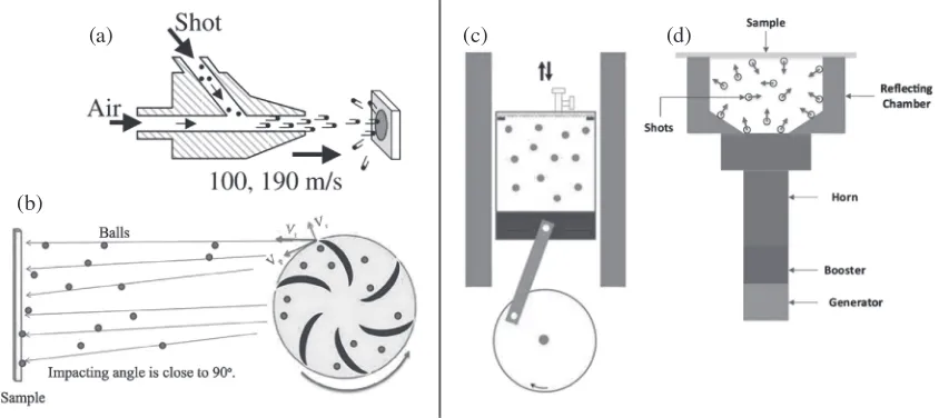
tools, for which the surface mechanical properties were improved by cold work hardening using controlled hammer-ing, were found near the ancient shoreline of the Persian Gulf. While the process of SP was considered as rather unpredictable during the early 19th century, continuous research has been conducted from 1920s onwards and it is now introduced into the product design specifications of numerous industrial components made of various steels (carbon, alloyed and stainless ones), aluminium and titanium alloys. Nowadays, processes deriving from the traditional pre-strain SP but involving much longer treatment durations and often higher velocity of the shots are being developed. These processes are classified in the following text under two different sections: (i) the directional “blast processes” (Figs. 1(a) and (b)) for which the shots are accelerated at high velocity for a given impact direction and (ii) the multi-directional types of processing (Figs. 1(c) and (d)) generating an interaction of the shots with the surface characterised by a broad range of different incidence angles. With the directional treatments, the shots are usually set in motion via compressed air (Fig. 1(a)) or by paddles of a rotating wheel (Fig. 1(b)). Comparatively, during the multidirectional treatments, the shots are set in motion within a confined chamber either by a rotating eccentric (³50 Hz Fig. 1(c)) or a vibrating/ resonating part called sonotrode (³20 kHzFig. 1(d)).
2.1 Directional peening
Shot blasting and sand blasting have initially been developed for oxide removal and surface cleaning but they also induce surface compressive residual stresses. In addition, the surface is plastically deformed and, from the high density of dislocations, NC grains of random orientation can be
created after annealing.31)For these techniques, the shot size and geometry are not rigorously controlled.
In comparison, for the air blast shot peening (ABSP), the shots are bigger, usually spherical or cut-wire, with a single size distribution and a sufficiently high hardness to induce compressive residual stresses and work hardening at the sample surface. A sketch of this process is given in Fig. 1(a).32)The shot are accelerated by compressed air and
their velocity have a narrow distribution.32)The air pressure,
shot size (usually from 0.125 to 1 mm), the nature of the shot material as well as the peening coverage are the controlled processing parameters. Peening coverage of 1000% can be maintained with a typical shotflow of 25 kg/min to induce severe peening leading to NC structure over tens of µm on steels.33,34) This treatment requires higher shot velocity (³80100 m/s) and larger coverage than those used for conventional shot peening. The rotationally accelerated shot peening (RASP) is another technique for which the shots are accelerated and projected on the target surface with centrifugal wheel paddles, allowing higher shot flow and impact energy than the ABSP technics.18)
While the overall direction of the shots with these techniques is rather unidirectional and determined by the process, it is generally possible to incline the blasting guns or the sample holders to modify the angle of incidence of the balls with respect to the surface. As it will be highlighted in section 4.2, it is also worthy to note that several of these technics of blast shot peening and centrifugal shot peening have been adapted to operate at higher temperatures than room temperature (RT).3537)
2.2 Multi-directional peening within a treatment cham-ber
Compared to conventional SP or the blast peening techniques mentioned previously, one of the major dif-ferences with the techniques depicted in the present section lies in the fact that the shots are set in motion within a confined chamber and, thereby, have a wide variety of
(a)
(b)
(c) (d)
Fig. 1 Illustration of different peening techniques: (a) air-blast shot peening (ABSP),32) (b) rotationally accelerated shot peening
(RASP),18)(c) mechanically driven surface mechanical attrition treatment (SMAT)102)and (d) ultrasonic shot peening (USP) or ultrasonic
[image:2.595.88.510.78.266.2]incidence angles when colliding onto the surface. Different techniques are found in the literature under various names such as Surface Mechanical Attrition Treatment (SMAT),38) Ultrasonic Shot Peening (referred to as USSP or USP)39) or High Energy Shot Peening (HESP).40,41) Despite different acronyms, the SMAT and USSP share the same concept but, while SMAT is generally used in academic manuscript, USSP and USP are more used in technical communications. Figures 1(c) and (d) illustrate two options that can be used to set the medias in motion: mechanical motion (Fig. 1(c)) or by using an ultrasonic device (Fig. 1(d)).
The ultrasonic version of these techniques uses a high energy and high frequency (typically 20 kHz) ultrasonic generator as the energy source. Shots are made of steels or ceramics for a typical ball size generally in the range 1 to 5 mm (up to 10 mm) in diameter. Using this type of ultrasonic SMAT, the surface is treated by shots impacting, multi-directionally, the surface at velocities that can reach about 10 m/s.42,43) For the HESP process, the lower frequency is balanced by bigger shots. Another technique is found under the acronym of surface nanocrystallisation and hardening (SNH).44,45)For this technique, the specimen is loaded at the end of a metallic tubular chamber containing few large balls that are shacked tri-dimensionally. This generates impacts on the sample surface having slightly different motion patterns than those obtained by the conventional ultrasonic machines.46)Finally, even if rather different from the initial
SMAT concept,13,38) other methods involving the collision
offlying ball onto a sample surface can also be found under the wording of surface mechanical attrition treatment. This is for example the case for the “stirred grinding” an “barrel grinding”devices used by Donget al.47)
In all cases after a sufficiently large number of impacts, various slip systems (potentially with twinning and strain induced phase transformation) are activated leading ulti-mately to a grain size refinement and substantial hardening of the surface and the subsurface. The thickness of the nanostructured domain at the surface generally reach 20 to 30 microns and the gradient microstructure where some hardening is also recorded can reach a thickness of some hundreds of microns. This behaviour was reported on a large variety of metals including, for example, Al,48) Cu49,50) or
austenitic stainless steels.33,34,39,42,5153)
3. Gradient Structures and Mechanical Properties
Using these “optimised” shot peening techniques, the mechanical performance of the overall material can be significantly enhanced through the formation of gradient-structures with refined surface microstructures. Considering steels for example, besides conventional use to harden the surface and improve wear54,55) and fatigue56) properties, tensile properties of the 316L57) and the 30442,58) stainless steels were also improved while multi-layered laminate composites were created by SMAT+subsequent roll bounding.59) One of the major characteristics considered
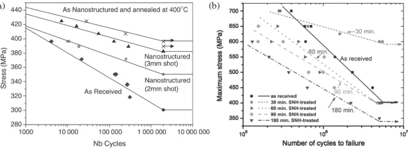
from an engineering standpoint is the resistance to fatigue under mechanical cyclic loading. During such solicitations, cracks generally nucleate at the surface which represents a particular zone subjected to specific features promoting cracks nucleation and propagation. The factors affecting the fatigue life of a component can be roughly divided into two main categories. First, the surface roughness, or the presence of stress raisers, influences essentially the initiation stage of crack growth.60) Second, the presence of residual stresses and structural defects which affects the crack propagation mechanics.6164)Thus, mechanical surface treatments, includ-ing the SMAT, are usually used to modify these properties and enhance the fatigue life. Figure 2(a) shows an application where the SMAT was used on a 316L stainless steel with two shot sizes.56) The association of a superficial refined
microstructure and a high compressive residual stress gradient allows to delay crack initiation and impede crack propagation. This was also observed on Fe,56,65,66) Ti67) or
Mg68)-based alloys. The use of mechanical surface treatment
also allows to push the initiation site under the peened surface raising the fatigue resistance69,70) and a component with a thicker surface nanostructure layer and deeper compressive residual stresses is expected to show improved fatigue properties. However, the peening energy also strongly influences the treated surface roughness71) and integrity which can impede the fatigue resistance of the compo-nents.67,72,73)An example is given in Fig. 2(b) where a C2000
superalloy was processed by SNH with different durations. The sample treated during 30 min (red) presented a better high cycle fatigue resistance whereas all the samples peened for longer time than 30 min possessed lower fatigue
(a) (b)
[image:3.595.91.510.70.223.2]resistances. This behavior was due to the generation of surface contamination and damages (cracks, ball indents+) during the SNH treatment that represent stress-concentration sites where cracks can initiate more easily.72) The negative
effect of microcracks after long SMAT was also revealed for the TA64 alloy.67)
It is then primordial to control the various treatment parameters in order to tailor precisely both (i) the surface and (ii) the gradient structure that finally control the related mechanical properties. From these examples, it is also clear that the changes in the gradient microstructure can be rather subtle and complex so that they require a good control of the processing parameters.
4. Modification of the Gradient Microstructure
For all the above-mentioned applications, the metallurgical and microstructural states of the deformed surfaces have to be tailored - by modifying the processing parameters - in a reproducible manner to form a controlled gradient micro-structure. Taking into account the structure of the grains and their misorientation, the microstructure in the gradient layer is generally depicted as the succession of three (or four if we include the NC zone) different zones: (i) the“ultrafine grain” (UFG) zone - which also contains the NC zone present at the extreme top surface - containing randomly oriented grains separated by the high angle grain boundaries, (ii) the
“transition zone” where grains were fragmented under the heavy plastic deformation and, finally, (iii) the “deformed zone” where initial grains are simply deformed.7476) The
exact nature of the transition zone depends on the deformation mechanisms that are involved in the grain refinement process (i.e. accumulation of dislocations at dense dislocation walls, formation of dislocation cells and subgrains, accommodation by twinning or martensite..). These mechanisms depend on the nature of the material and, particularly, on its stacking fault energy. A number of papers have investigated the deformation and grain refi ne-ment mechanisms under SMAT. These mechanisms depend also on the local strain rate but are rather consistent with those observed for other SPD processes. The thicknesses of the different zones depend on the magnitude of the processing parameters used for imparting the energy to the surface.
4.1 Effect of conventional processing parameters
To control the exact nature of the gradient structure, it is thus primordial to understand the role of each of the processing parameters and their interactions. Indeed, the impact density and the shot velocities are the result of a combination of various processing parameters such as the shot characteristics (quantity, diameter and nature), the vibrating amplitude that set the shots in motion and the duration of the treatment. Several research works have investigated the effects of the processing parameters on the extent of surface hardening and the nature of the in-depth microstructure gradients.42,74,77) For example, Chen et al.77)
have used two sets of SMAT processing parameters (vibrating frequencies, nature and diameter of the balls) to treat the 304 stainless steel under low (0.5 m.s¹1) and high
(10 m.s¹1) speeds of the shots. In this way, for similar surface
hardness, different sub-surface hardness gradients were obtained, resulting in different mechanical behaviour for thin (1 mm) plates SMATed on both sides. Several re-sults,55,74,77,78) among others, indicate that increasing the energy imparted to the surface - via an increase in vibration amplitude and/or treatment duration - allows to increase the material hardness deeper in the material. The control of this evolution, and thus the separate effect of the processing parameters, remains generally quite qualitative. In order to characterize quantitatively the thickness of the different layers of the graded structure, Samih et al.74) have
established an automated procedure - based on an analysis of geometrically necessary dislocations (GNDs) coupled with indexing and size criteria - obtained from various Electron BackScattered Diffraction (EBSD) maps carried out at different magnifications. Under their tested processing conditions - varying the amplitude of vibration and treatment duration - these authors have established that the UFG and transition zones were more significantly modified than the overall affected thickness for a 316L stainless steel. Because the spatial resolution of EBSD is not high enough to fully depict the NC structure in the UFG zone, such type of approach was coupled with Transmission Kikuchi Diffraction (TKD) analyses in the SEM75)or with TEM.76)However, in view of potential and reproducible industrial applications, a large amount of work remains to be done to establish quantitatively the effect of the comparative effect of each processing parameter.
4.2 Effect of the shot peening temperature
One of the important processing parameters that has received so far little attention is the temperature at which the severe shot peening is carried out. Processing by SPD of bulk material at cryogenic temperature (CT) has been done previously to prevent dynamic recovery and stimulate mechanical twinning in order to, in both cases, enhance the grain refinement.79) The use of cryogenic deformation by rolling/drawing, equal channel angular extrusion (ECAE), or high pressure torsion (HPT) has been tested on aluminium alloys, copper, and brass.8084) Following the same idea, to reduce further the size of the surface microstructure, cryogenic surface treatments have also been developed such as cryogenic surface mechanical grinding,85) cryogenic
burnishing,86) cryogenic laser shot peening,87) cryogenic
impact,88) as well as the SMAT/USSP processes applied at
low temperature.52,53,8992) Again, all these new techniques
were essentially applied to alloys with low/medium melting points such as Mg alloys86)or Cu,85,8790)and brass.91)Much
or martensitic transformation can compete with conventional slip systems to accommodate plastic deformation. With this goal, Novelliet al.52)have carried out a comparative analysis
of the SMAT behaviour of two austenitic stainless steels having different stabilities of their austenitic phases with regards to a potential martensitic transformation. They used the 310S steel, which is extremely stable against the martensitic transformation (Md30=¹169°C), and the 304L
steel for which a martensitic transformation should be promoted at CT and even triggered at RT under loading (Md30=21°C). Consistently with other results on material
SMATed at CT8992)finer nanostructures were obtained at the
top-surfaces after peening at CT over a depth of about 5 µm for both materials. However, the most interesting results were obtained for the subsurface hardness evolution. This is illustrated for the two alloys in Fig. 3 where the cross-section hardness evolutions obtained after SMAT at RT are compared with the hardness evolutions after SMAT at CT. For the metastable 304L steel, an increase of the subsurface hardness is clearly visible along the first 300 µm (arrow in Fig. 3) when processing was done at CT. As was confirmed by
EBSD analysis,52) this is the direct result of the decrease
in peening temperature that promotes the strain induced martensitic transformation deeper in the subsurface. Thus peening at CT can be justified for this kind of TRans-formation Induced Plasticity (TRIP) steels if subsurface hardenings are targeted. Comparatively, as the TRIP mechan-ism is not active in the stable 310S steel, no benefit could be gained in the subsurface region. On the contrary, because the strength of the material increases at CT, this has made it more difficult to impart plastic deformation. Thus, the size of the subsurface affected region decreases (double arrowed in Fig. 3) for the same given set of processing parameters. The detailed analysis of the effect of various processing parame-ters - including CT - on the 304L steel as revealed that the gradient structure in such TRIP steels is, in fact, the superimposition of different graded microstructure: one in terms of grain size, the other one in terms of phase distribution.53) For example, the maximum amount of
martensite was never found in the vicinity of the extreme surface, where the finest grains were present, but at 50 to 100 µm below the surface depending on the processing conditions. This aspect is important to interpret correctly the hardening in SMATed materials in which a phase trans-formation can take place. In addition, as crack propagation is affected by the grain size as well as by the presence of martensite, it is likely that this is also an important issue to take into account to improve fatigue properties; properties that appears to be sensitive to the SMAT processing conditions (see previous section).
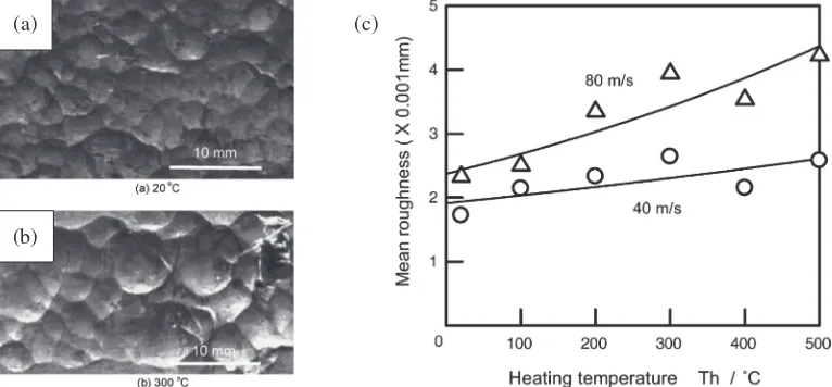
As pointed out in several contributions under warm condition36,37,93) or CT,53) the peening temperature has a
strong effect on the surface roughness evolutions. This is illustrated in Fig. 4 by the optical microscopy observations and the mean roughness Ra plotted as a function of the
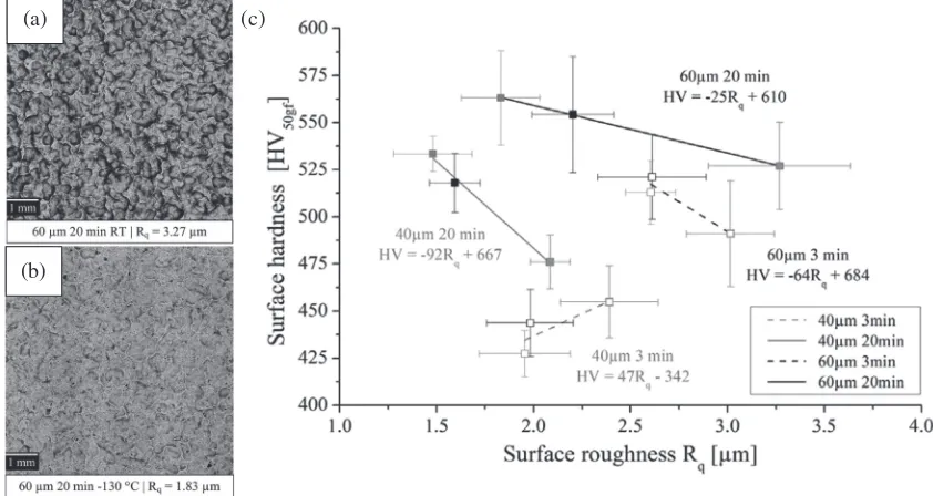
peening temperature taken from the work of Ref. 37). The surface roughness increases when the process temperature is raised. Consistently, as illustrated by the two images given in Figs. 5(a) and 5(b), as the material becomes harder at lower temperature, the shots leave less pronounced impacts on the material surface. This leads to a clear decrease of the apparent surface roughness at CT.53)For ultrasonic shot peening, the
Fig. 3 Effect of the ultrasonic SMAT temperature on the transversal hardness gradient (RT=20°C, CT=¹130°C) for two steels having different stabilities. Dotted lines represent the hardness measured after SMAT under CT.52)
(a)
(b)
(c)
[image:5.595.107.490.581.759.2]amplitude of the sonotrode, that is inducing the kinetic energy to the flying shots, is also a factor affecting strongly the surface roughness for a given type of shot. The highest roughness is generally obtained for the highest amplitudes of the sonotrode. On the other hand, it is possible to lower the roughness by increasing the treatment time (i.e. amount of impacts) and, more efficiently, by lowering the peening temperature. Thus, for a given type of shots (size and weight), it is possible to lower the roughness by using a
“moderate” sonotrode amplitude, increasing the treatment time and, more significantly, by lowering the peening temperature. Figure 5(c) illustrates the direct correlation between the surface roughness and top surface hardness for different sets of processing parameters: for 3 different temperatures (RT, ¹80°C and ¹120°C) with the sonotrode amplitude varying from 40 to 60 µm and the treatment time from 3 to 20 min. The treatments done with the highest sonotrode amplitude of 60 µm (full and dotted black lines) generally provide with higher values of surface hardness and roughness than the 40 µm ones (full and dotted grey lines). Figure 5(c) indicates that it is possible, for this 304L steel, to use the various processing parameters to tailor the surface properties and produce a hard surface (about 530 HV) having either smooth (Rq=1.6 µm) or rough (Rq=3.3 µm) profiles. Comparatively, it is possible to adjust a surface having a roughness of about 2 µm with hardness values varying in the range 425 HV up to 560 HV. Thus, the use of CT is an additional parameter during ultrasonic SMAT that allows to tailor the surface properties towards tribological applications by controlling the surface hardness and rough-ness rather independently.53)
As far as the temperature of peening is concerned, as proved by results on steels36,37)and Mg alloys,93)increasing
slightly the peening temperature (200300°C) can be a good idea to improve the fatigue life or fatigue strength. The increase in peening temperature generally generates higher
subsurface hardening and larger maximum compressive residual stresses.93) Thus, for an optimum Almen intensity, the surface of the warm shot peened specimen is more plastically deformed but less“damaged”due to the increase in plastic deformation ability.93) Also, the dislocation
structure is likely to be modified towards a higher stability.36)
5. Improved Surface Reactivity
The high fraction of structural defects in NC or UFG materials can lead to a significant increase in stored energy which, inevitably, increases the material reactivity in comparison to the CG materials. For some potential applications, the effect may depend on the nature of the structural defects (i.e. high angle grain boundaries (HAGB), low angle grain boundaries (LAGB), dislocations +). In addition to modify the corrosion or oxidation properties, these refined gradient structures have been proved to activate the kinetics of chemical reactions (for phosphatation, nitriding+) and some potential applications are raising for hydrogen storage processes. These different aspects are shortly reviewed hereafter into 3 different sections.
5.1 Corrosion resistance
In some cases, the higher reactivity may not be suitable or lead to a dual behaviour depending on the material environment. This is for example the case for corrosion, for which improvements or deleterious effects can be obtained for the same material depending on the location on the EH-pH Pourbaix diagram. In the case of stainless steels for example, a decrease in corrosion resistance is reported in depassivating electrolytes while the higher reactivity of the SMATed surface helps to create faster a passivating (i.e. protective) film in many aqueous environments.94,95) The
easier formation of a more stable passive film was also observed for surfaces treated by high energy shot-peening.96)
(a) (c)
(b)
[image:6.595.86.507.74.298.2]However, there is at present a significant amount of research concerning the corrosion behaviour of metals treated by SMAT or USSP types of technology - again indicating either beneficial of deleterious effects (see for example Ref. 97)) -suggesting that other factors than the grain size and/or the amount of structural defects must be taken into account. In addition to this, it is likely that the corrosion resistance in NC materials is also very much dependant on the processing route used to generate the structure.98) Indeed, these processing routes generally affect other parameters than the grain size such as the chemical homogeneity, size and distribution of inclusions, dislocation densities or solid solubility; parameters which are equally important for corrosion properties. In the case of NC surfaces produced by severe shot peening, some cracking and inclusions from the processing media or local contaminations by abrasion of the treatment chamber are also important factors affecting the surface reactivity. For example, Haoet al.99)analysed the
decrease in pitting resistance of SMATed samples as the result of the formation of cracks during the attrition treatment. Also, the corrosion resistance of magnesium100) and that of a 2024 Al alloy101)were found to be affected by surface contamination (mainly Fe and Fe-oxides) resulting from the SMAT treatment. The presence of contamination at the surface of SMATed samples is now clearly established and depends on the exact way of processing. Indeed, Fe and Cr can be introduced from the stainless steel balls and chamber walls,101,102) Al and Zr from the ceramic shots,103)
while Ti (+Al and V) could come from the sonotrode when an ultrasonic device was used.103,104) For example, in their
work, Alikhani Chamgordani et al.102) have used a SMAT
machine with a steel chamber in which the shots were set in motion via a mechanical device (see Fig. 1(c)). It was confirmed by XRD and EDS analyses that a fairly large amount of Fe and FeO contamination was deposited on the surface of the samples when they were SMAT treated with this machine.102) This contamination originated from the abrasion of balls and contained interior walls.102) Compara-tively, the machine used by Samihet al.,103)such as the one seen in Fig. 1(d), uses an ultrasonic power supply that is moving a Ti6Al4V sole that, itself, sets the shots in motion. Transmission electron microscopy and glow discharge -optical emission spectroscopy - have revealed a contami-nation rich in Ti with a little of Al and V at the surface of the steel samples treated with this ultrasonic SMAT device together with some surface embedded pieces induced by the zirconium based shots.103) As it is well established that
corrosion of aluminium alloys is influenced by the presence, even at low levels, of iron impurities,105) probably the best
example of processing influence on corrosion modification after SMAT is given by the work of Wenet al.106)who have demonstrated that the corrosion resistance of a 2024 Al alloy was directly affected by the nature of the shot peen media. Indeed, while the NC layer fabricated by SMAT with ceramic balls improved the corrosion resistance because of the formation of a dense passive film, the Fe containing layer induced by SMAT with the steel shots led to galvanic corrosion reaction between Fe and Al.106)To this respect, a
recent analysis of the corrosion in two aluminium alloys (AA 2024 and AA 7150) has shown the dual effect of such
treatment: the dissolution of the nano-sized strengthening precipitates in the Al matrix and grain refinement generated under the USSP treatment have improved the intergranular corrosion resistance while the overall corrosion rate was increased by the Fe contamination.107) To counterbalance, or at least mitigate, the potential effect of the surface contamination, Murdoch et al.108) have introduced a pre-processing step (pre-coating of the shot media and chamber) to reduce the resulting impact on corrosion properties.
5.2 Use of increased surface reactivity for “duplex” treatments
Due to the imparted severe plastic deformation and the high quantity of structural defects generated at the surface, SMAT has been used within“duplex”treatments, to enhance the kinetics of diffusion for several chemically assisted industrial processes such as nitriding,109,110) pack
boroniz-ing,111) aluminizing,112) chromizing113) as well as plasma
electrolytic oxidation (also known as microarc oxidation).114)
Among these duplex “SMAT assisted” thermo-mechanical treatments, nitriding has been the most widely investigated and debated one. Indeed, nitriding - which is indeed one of the most widely employed surface treatment used to improve hardness, wear resistance and corrosion resistance of metallic materials115117) - could benefit in different ways from such an activation treatment. As the nitriding process applied to SMATed NC iron specimens revealed enhanced atomic diffusivities as well as enhanced chemical reaction ki-netics,109,110,118) nitriding could either generate thicker
layers (when nitriding was carried out at the same temperature) or authorise lower nitriding temperatures. This option of carrying the nitriding treatment at temperature as low as 300°C is of primary importance for the quality of the corrosion properties in austenitic stainless steels because it keeps a single phase structure of (£N) expended austenite
and avoids the precipitation of Cr-rich nitrides. It is important to note that analogue results were found showing the positive effect of an UFG structure (produced by HPT) concerning the formation of a thick layer of expanded austenite without any precipitation of Cr-nitride by Ferkelet al.;119,120)but still, the effectiveness of producing SPD at the surface has more practical applications.
Even if the SMAT is sometimes done under vacuum, mechanical attrition of the surface by ball milling used as a pre-treatment of stainless steels prior to nitriding has been proved in previous studies to induce an oxide contamination of the surface that blocked the nitrogenflux and reduced the nitrided layer thickness.121123) Further analysis has shown
that this contamination, acting as a barrier to the nitrogen
flux, could also result from the material transfer of fragments coming from different constitutive parts of the SMAT treating machine103)and lead to discontinuous nitriding layers. Thus, chemical etching124) or mechanical polishing75,103,122,125) were used as an intermediary stage during such duplex treatment process to reduce the surface contamination and, thereby, improve further the quality and thickness of the nitrided layers.
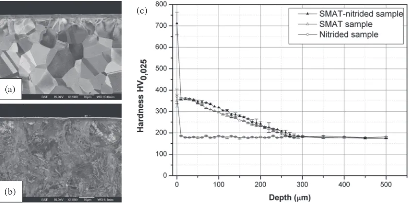
illustrated in Fig. 6 where the comparison of the surface and subsurface hardnesses are compared for a 316L stainless steel nitrided at 350°C in a gas mixture of 20%N2+80%H2. The
sample that was only nitrided (Fig. 6(a)) presented a nitrided surface of single-phase austenite having a thickness of about 3 µm and a hardness of about 380 HV (Fig. 6(c)). The same level of surface hardness was reached for the SMATed sample but with a subsurface hardening extending over 280 µm (Fig. 6(c)). For the SMAT+nitrided sample (Fig. 6(b)), the nitrided layer is hardened by a combination of plastic hardening due to the SPD as well as solute hardening due to the presence of the N-enriched austenite to a hardness value of 720 HV (Fig. 6(c)). At the same time, the subsurface hardening induced by the SMAT was maintained (Fig. 6(c)).
5.3 Assistance for H-activation
For automotive and energy applications, a considerable amount of research has been devoted to develop advanced H-storage media in solid-state materials by forming metal hydrides.126)Following the pioneer works of Skripnyuket al.
using ECAP and high energy ball milling (HEBM)127,128) as
well as thefirst work by Kosadumeet al.involving HPT,129)
several processing routes of SPD processing have been employed for enhancing the hydrogen sorption properties of metallic materials, in particular in Mg based alloys130133)that
possess a high storage capacity. Perhaps, the best example on the effect of SPD on activation was reported for the TiFe intermetallic after HPT.134) While TiFe - that was first introduced as a hydrogen storage material by Reilly and Wiswall in 1974135)- can thermodynamically store hydrogen at RT, its hydrogenation requires a first activation process at high temperature and/or under high pressure.135) Edalati
et al. reported that the HPT-processed TiFe can reversibly absorb and desorb hydrogen at RT without any activation treatment; and this even after 400-day storage in air.134)It was
suggested that the main mechanism for the HPT-induced activation was the formation of large fraction of grain boundaries acting as pathways for hydrogen.134)
Since the activation for hydrogenation is mainly a surface-related issue involving the separation of H2molecules at the
surface to create H atoms which subsequently diffuse from the surface towards the bulk,136)it is surprising to realise that, compared to an appreciable number of publications on the effect of bulk SPD processing on hydrogen storage proper-ties, there has been only one attempt to modify the hydrogen storage properties by a ultrasonic SMAT method.137)To test
the potential of severe plastic deformation at the surface to ease reversibly H-storage properties, the TiVCr system was used. Indeed, the room-temperature dehydrogenation capa-bility of alloys based TiVCr makes them rather attractive but, as for the TiFe alloy, they need an initial thermal activation process (typically at temperatures up to 673 K) to react with hydrogen in the first hydrogenation cycle.138) In addition, their reversibility appears to be degraded by the presence of structural defects.139,140) Thus, the gradient microstructure produced by SMAT could have a very high potential for assisting the H storage at the surface while using the inner, non deformed, core of the material for reversible storage. To understand the significance of gradient-structures on hydrogen storage, a comparative H-storage study was carried out on TiVCr alloys deformed by SMAT for rather short times (8 minutes) and HPT for a quite severe straining (100 turns).
Figure 7 shows the pressure-composition-temperature (PCT) isotherms for samples processed by (a) SMAT and (b) HPT (PCT was conducted at 303 K for the first two cycles and at 353 K for the third cycle). Although TiVCr alloy after both SMAT and HPT processing interestingly absorbs hydrogen without any activation treatment, only the SMAT-processed alloy exhibits ³2 wt.% hydrogen storage reversibility.
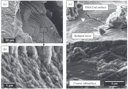
Views of the particles coming from hydrogenation of the SMAT- and HPT-processed Ti10V75Cr15 alloy can be seen
Fig. 8. It should be recalled here that the powder were formed
“naturally” by a fragmentation mechanism, known as hydrogen pulverization,141,142) which is governed by the
repeated expansion/contraction of the lattice volume induced
(a)
(b)
(c)
[image:8.595.89.510.70.279.2]by the hydrogen diffusion. Figure 8(c) shows a SEM image taken directly at the surface that was previously peened by the SMAT process (marked with a triangle) and easily recognisable by its undulated aspect generated by the shot impacts. The refined layer generated by the SMAT is clearly visible along the first few microns under the treated surface and is followed by a coarser structure. It is interesting to note that this gradient structure is not as pronounced as the gradient structure generally observed after SMAT of ductile materials such as Al,48) Cu49,50) or austenitic stainless
steel.33,5153) This is because of the short time of peening
and the brittle nature of the TiVCr alloys. The views of a HPT particle Fig. 8(a) and (b) featured significant differences from the ones observed on the SMAT particles. The
nanostructure generated by SPD via the HPT process before hydrogenation is clearly visible in Fig. 8(b): the ultrafine grains produced under the HPT processing are surrounded by a different type of contrast along the grain boundaries. As grain boundaries are known to be shortcuts for diffusion, it is likely that this contrast witnesses hydrogen diffusion along the grain boundaries where the“brittle”fracture subsequently took place. As seen in the upper part of the image in Fig. 8(a), a particular structure containing numerous elongated features is also visible. These structures are thought to be induced by the hydrogen paths created during hydrogen diffusion that are, possibly, driven by some local strain heterogeneities.143)
As revealed by the PCT curves of the HPT processed samples, it is likely that the grain boundaries have eased the
(a) (b)
Fig. 7 PCT isotherms of a Ti10V75Cr15alloy processed by (a) HPT and (b) SMAT. Sample were evacuated at 303 K for 2 h before each
cycle.137)
(a)
(b)
(c)
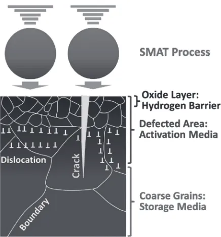
[image:9.595.89.511.67.231.2] [image:9.595.82.513.276.576.2]H-diffusion but, also, unfortunately dropped the H-desorption to prevent good reversibility. Comparatively, as illustrated in Fig. 9, the gradient structure created by SMAT had its own advantages. First, the nanostructure and cracks present at the surface of the SMATed sample could act as a pathway for hydrogen transport through the oxide layer and activate the material for H-storage. Second, the H-atoms could be stored in the defect-free subsurface where more reversibility is expected. Thus, processes inducing severe shot peening may be regarded as having a high potential for elaborating industrially H-storage materials.137)
6. Conclusions
The aim of this short overview was not to cover the overall
field related to surface modification by severe plastic deformation involving shot peening related processes but more to highlight some recent results that the authors believe are important to get new insights in thisfield.
Section 2 of this manuscript shortly presents various techniques that use shots to induce surface severe plastic deformation. Because of their different ability to induce NC structures, these processes that are deriving from the traditional pre-strain SP have been classified into two different sub-sections: the directional “blast” processes for which the shots are accelerated at high velocity for a given impact direction and the“multi-directional”types of process-ing generatprocess-ing continuously a broader range of incidence angles of the shots with the surface.
The advantages of having a gradient structure for mechanical properties is shortly recalled in section 3, with a particular emphasis on fatigue properties. Considering fatigue, it becomes evident that both the control of (i) the integrity of the top surface and (ii) the quality and nature of the subsurface gradient structure are important.
The importance of controlling the processing parameters to get the optimum gradient structure depending on the
desired applications as well as the necessary requirements for a high quality microstructure and chemical characterizations are also highlighted in section 4. In this section, a special attention is devoted to the use of the temperature (cryogenic peening or warm peening) - that can modify the deformation mechanisms and the stability of the structural defects - as an additional processing parameter to control the gradient microstructure.
The last section (section 5) aims at underlying the advantages of the “reactivity” of these modified surfaces for improving corrosion resistance and for combining -within “duplex”treatments - the SPD with surface thermo-chemical treatments. Here, the importance of controlling some potential surface contamination - or better, using it in a proper and useful way - is stressed. Finally, the manuscript terminates on the potential of the surface NC and control of the gradient microstructure produced by SMAT for applications in thefield of H-storage materials.
Acknowledgements
The authors would like to thank the support of the French State through the program “Investment in the future” operated by the National Research Agency (ANR) and referenced by ANR-11-LABX-0008-01 (Labex DAMAS).
The authors would like to thank warmly Dr. Grégory Marcos and Pr. Thierry Czerwiec from the Institut Jean Lamour in Nancy for performing the nitriding experiments (shown in Fig. 6) and for fruitful and friendly discussions.
REFERENCES
1) H. Gleiter:Acta Mater.48(2000) 129.
2) R.Z. Valiev, R.K. Islamgaliev and I.V. Alexandrov:Prog. Mater. Sci.
45(2000) 103189.
3) Y.T. Zhu, T.C. Lowe and T.G. Langdon:Scr. Mater.51(2004) 825 830.
4) R.Z. Valiev, Y. Estrin, Z. Horita, T.G. Langdon, M.J. Zehetbauer and Y. Zhu:JOM68(2016) 12161226.
5) K. Edalati and Z. Horita:Mater. Sci. Eng. A652(2016) 325352. 6) V.M. Segal:Mater. Sci. Eng. A271(1999) 322333.
7) T. Fujioka and Z. Horita:Mater. Trans.50(2009) 930933. 8) Y. Saito, H. Utsunomiya, N. Tsuji and T. Sakai:Acta Mater.47(1999)
579583.
9) B. Beausir, J. Scharnweber, J. Jaschinski, H.G. Brokmeier, C.G. Oertel and W. Skrotzki:Mater. Sci. Eng. A527(2010) 32713278. 10) L.S. Toth, M. Arzaghi, J.J. Fundenberger, B. Beausir, O. Bouaziz and
R. Arruffat-Massion:Scr. Mater.60(2009) 175177.
11) P. Groche, D. Vucic and M. Jöckel:J. Mater. Process. Technol.183
(2007) 249255.
12) L.S. Toth, C. Chen, J.-J. Fundenberger, R. Kulagin, Y. Beygelzimer and V.Q. Vu:Mater. Charact.138(2018) 208214.
13) K. Lu and J. Lu:Mater. Sci. Eng. A375377(2004) 3845. 14) J.L. Liu, M. Umemoto, Y. Todaka and K. Tsuchiya:J. Mater. Sci.42
(2007) 77167720.
15) B.N. Mordyuk and G.I. Prokopenko:J. Sound Vib.308(2007) 855 866.
16) M. Multigner, S. Ferreira-Barragáns, E. Frutos, M. Jaafar, J. Ibáñez, P. Marín, M.T. Pérez-Prado, G. González-Doncel, A. Asenjo and J.L. González-Carrasco:Surf. Coatings Technol.205(2010) 18301837. 17) M. Yasuoka, P. Wang, K. Zhang, Z. Qiu, K. Kusaka and Y.S. Pyoun:
Surf. Coatings Technol.218(2013) 9398.
18) X. Wang, Y.S. Li, Q. Zhang, Y.H. Zhao and Y.T. Zhu:J. Mater. Sci. Technol.33(2017) 758761.
19) H.W. Huang, Z.B. Wang, J. Lu and K. Lu:Acta Mater.87(2015) 150 Fig. 9 Schematic illustration of hydrogen behavior of TiVCr alloys with
[image:10.595.60.278.66.300.2]160.
20) S.Q. Deng, A. Godfrey, W. Liu and N. Hansen:Scr. Mater.117(2016) 4145.
21) D. Liu, D. Liu, X. Zhang, C. Liu and N. Ao:Mater. Sci. Eng. A726
(2018) 6981.
22) C.S. Montross, T. Wei, L. Ye, G. Clark and Y.W. Mai:Int. J. Fatigue
24(2002) 10211036.
23) A.D. Pogrebnjak, V.S. Ladysev, N.A. Pogrebnjak, A.D. Michaliov, V.T. Shablya, A.N. Valyaev, A.A. Valyaev and V.B. Loboda:Vacuum
58(2000) 4552.
24) J. Zou, T. Grosdidier, K. Zhang and C. Dong:Acta Mater.54(2006) 54095419.
25) J.X. Zou, T. Grosdidier, B. Bolle, K.M. Zhang and C. Dong:Metall. Mater. Trans. A38(2007) 20612071.
26) V.S. Krasnikov and A.E. Mayer:Surf. Coatings Technol.212(2012) 7987.
27) V. Schulze: Proceeding of the Eighth International Conference on Shot Peening ICSP-8 in Garmisch-Partenkirchen DGM, (2002) pp. 147160.
28) S. Bagheri and M. Guagliano:Surf. Eng.25(2009) 314.
29) J. Azadmanjiri, C.C. Berndt, A. Kapoor and C. Wen:Crit. Rev. Solid State Mater. Sci.40(2015) 164181.
30) P.P. Shukla, P.T. Swanson and C.J. Page:Proc. Inst. Mech. Eng. Part B J. Eng. Manuf.228(2014) 639652.
31) L. Wang and D.Y. Li:Surf. Coatings Technol.167(2003) 188196. 32) Y. Todaka, M. Umemoto and T. Koichi:Mater. Trans.45(2004) 376
379.
33) S. Bagherifard, S. Slawik, I. Fernández-Pariente, C. Pauly, F. Mücklich and M. Guagliano:Mater. Des.102(2016) 6877. 34) M. Jayalakshmi, P. Huilgol, B.R. Bhat and K. Udaya Bhat: Surf.
Coatings Technol.344(2018) 295302.
35) A. Wick, V. Schulze and O. Vöhringer:Mat.-Wiss. u. Werkstofftech.
30(1999) 269273.
36) A. Wick, V. Schulze and O. Vöhringer:Mater. Sci. Eng. A293(2000) 191197.
37) Y. Harada and K. Mori:J. Mater. Process. Technol.162163(2005) 498503.
38) K. Lu and J. Lu: J. Mater. Sci. Technol.15(1999) 193197. 39) G. Liu, J. Lu and K. Lu:Mater. Sci. Eng. A286(2000) 9195. 40) L. Zhiming, S. Laimin, Z. Shenjin, T. Zhidong and J. Yazhou:Mater.
Sci. Eng. A637(2015) 170174.
41) G. Liu, S.C. Wang, X.F. Lou, J. Lu and K. Lu:Scr. Mater.44(2001) 17911795.
42) H.L. Chan, H.H. Ruan, A.Y. Chen and J. Lu:Acta Mater.58(2010) 50865096.
43) J. Badreddine, E. Rouhaud, M. Micoulaut and S. Remy:Int. J. Mech. Sci.82(2014) 179190.
44) K. Dai, J. Villegas, Z. Stone and L. Shaw:Acta Mater.52(2004) 57715782.
45) J.C. Villegas, K. Dai, L.L. Shaw and P.K. Liaw:Mater. Sci. Eng. A
410411(2005) 257260.
46) L.L. Shaw, J.W. Tian, A.L. Ortiz, K. Dai, J.C. Villegas, P.K. Liaw, R. Ren and D.L. Klarstrom:Mater. Sci. Eng. A527(2010) 986994. 47) X. Dong, D. Wang and Y. Zeng:J. Rare Earths32(2014) 867873. 48) Y. Liu, B. Jin and J. Lu:Mater. Sci. Eng. A636(2015) 446451. 49) K. Wang, N.R. Tao, G. Liu, J. Lu and K. Lu:Acta Mater.54(2006)
52815291.
50) R. Blonde, H.L. Chan, N. Allain-Bonasso, B. Bolle, T. Grosdidier and J. Lu:J. Alloys Compd.504(2010) S410S413.
51) H. Zhang, Z. Hei, G. Liu, J. Lu and K. Lu:Acta Mater.51(2003) 18711881.
52) M. Novelli, J.-J. Fundenberger, P. Bocher and T. Grosdidier:Appl. Surf. Sci.389(2016) 11691174.
53) M. Novelli, P. Bocher and T. Grosdidier:Mater. Charact.139(2018) 197207.
54) Z.B. Wang, J. Lu and K. Lu:Surf. Coatings Technol. 201(2006) 27962801.
55) Y. Sun:Tribol. Int.57(2013) 6775.
56) T. Roland, D. Retraint, K. Lu and J. Lu:Scr. Mater.54(2006) 1949 1954.
57) X.H. Chen, J. Lu, L. Lu and K. Lu: Scr. Mater.52 (2005) 1039
1044.
58) X.L. Wu, M.X. Yang, F.P. Yuan, L. Chen and Y.T. Zhu:Acta Mater.
112(2016) 337346.
59) L. Waltz, D. Retraint, A. Roos and P. Olier:Scr. Mater.60(2009) 21 24.
60) P.S. Maiya and D.E. Busch:Metall. Trans. A6(1975) 17611766. 61) G.A. Webster and A.N. Ezeilo:Int. J. Fatigue23(2001) 375383. 62) R.C. McClung:FFEMS30(2007) 173205.
63) K. Dai and L. Shaw:Mater. Sci. Eng. A463(2007) 4653. 64) I.F. Pariente and M. Guagliano: Surf. Coat. Technol. 202 (2008)
30723080.
65) J. Uusitalo, L.P. Karjalainen, D. Retraint and M. Palosaari:Mater. Sci. Forum604605(2009) 239248.
66) J. Zhou, Z. Sun, P. Kanouté and D. Retraint:Int. J. Fatigue103(2017) 309317.
67) S.A. Kumar, S.G.S. Raman and T.S.N.S. Narayanan:Trans. Indian Inst. Met.67(2014) 137141.
68) G. Chen, J. Gao, Y. Cui, H. Gao, X. Guo and S. Wu:J. Alloys Compd.
735(2018) 536546.
69) M. Torres and H.J.C. Voorwald:Int. J. Fatigue24(2002) 877886. 70) K. Masaki, Y. Ochi and T. Matsumura:Fatigue Fract. Eng. Mater.
Struct.27(2004) 11371145.
71) S. Bagherifard, R. Ghelichi and M. Guagliano:Appl. Surf. Sci.258
(2012) 68316840.
72) J.W. Tian, J.C. Villegas, W. Yuan, D. Fielden, L. Shaw, P.K. Liaw and D.L. Klarstrom:Mater. Sci. Eng. A468470(2007) 164170. 73) V. Pandey, K. Chattopadhyay, N.C. Santhi Srinivas and V. Singh:Int.
J. Fatigue103(2017) 426435.
74) Y. Samih, B. Beausir, B. Bolle and T. Grosdidier:Mater. Charact.83
(2013) 129138.
75) G. Proust, D. Retraint, M. Chemkhi, A. Roos and C. Demangel: Microsc. Microanal.21(2015) 919926.
76) W. Liu, X. Jin, B. Zhang, D. Yun and P. Chen:Materials (Basel)12
(2019) 140.
77) A.Y. Chen, H.H. Ruan, J. Wang, H.L. Chan, Q. Wang, Q. Li and J. Lu: Acta Mater.59(2011) 36973709.
78) T. Roland, D. Retraint, K. Lu and J. Lu:Mater. Sci. Eng. A445446
(2007) 281288.
79) K. Edalati, J.M. Cubero-Sesin, A. Alhamidi, I.F. Mohamed and Z. Horita:Mater. Sci. Eng. A613(2014) 103110.
80) Y. Huang and P.B. Prangnell:Acta Mater.56(2008) 16191632. 81) T. Konkova, S. Mironov, A. Korznikov and S.L. Semiatin: Acta
Mater.58(2010) 52625273.
82) T. Konkova, S. Mironov, A. Korznikov and S.L. Semiatin:Scr. Mater.
63(2010) 921924.
83) A. Chatterjee, G. Sharma, A. Sarkar, J.B. Singh and J.K. Chakravartty:Mater. Sci. Eng. A556(2012) 653657.
84) T. Konkova, S. Mironov, A. Korznikov, G. Korznikova, M.M. Myshlyaev and S.L. Semiatin:Mater. Charact.101(2015) 173179. 85) W.L. Li, N.R. Tao and K. Lu:Scr. Mater.59(2008) 546549. 86) Z. Pu, S. Yang, G.L. Song, O.W. Dillon, D.A. Puleo and I.S. Jawahir:
Scr. Mater.65(2011) 520523.
87) C. Ye, S. Suslov, D. Lin, Y. Liao and G.J. Cheng:J. Appl. Phys.115
(2014) 213519.
88) W. Luo, H. Gong, Q. Wang, J. Lu and M. Yan:Mater. Lett.157(2015) 315317.
89) K.A. Darling, M.A. Tschopp, A.J. Roberts, J.P. Ligda and L.J. Kecskes:Scr. Mater.69(2013) 461464.
90) Y. Shen, C. Wen, X. Yang, Y. Pang, L. Sun, J. Tao, Y. Gong and X. Zhu:J. Mater. Eng. Perform.24(2015) 50585064.
91) B. Cai, X. Ma, J. Moering, H. Zhou, X. Yang and X. Zhu:Mater. Sci. Eng. A626(2015) 144149.
92) H.A. Murdoch, K.A. Darling, A.J. Roberts and L. Kecskes:Metals (Basel)5(2015) 976985.
93) Y. Huang, W.C. Liu and J. Dong: Mater. Sci. Technol.30(2014) 14811487.
94) K.D. Ralston and N. Birbilis:Corrosion66(2010) 14.
95) L. Liu, Y. Li and F. Wang:J. Mater. Sci. Technol.26(2010) 114. 96) T. Wang, J. Yu and B. Dong: Surf. Coatings Technol.200(2006)
47774781.
(2017) 469479.
98) R.K. Gupta and N. Birbilis:Corros. Sci.92(2015) 115.
99) Y.W. Hao, B. Deng, C. Zhong, Y.M. Jiang and J. Li:J. Iron Steel Res. Int.16(2009) 6872.
100) D. Fabijanic, K.D. Ralston, N. Birbilis, A. Taylor and M.-X. Zhang: Corrosion69(2013) 527535.
101) L. Wen, Y. Wang, Y. Zhou, L.X. Guo and J.H. Ouyang:Mater. Chem. Phys.126(2011) 301309.
102) S. Alikhani Chamgordani, R. Miresmaeili and M. Aliofkhazraei: Tribol. Int.119(2018) 744752.
103) Y. Samih, M. Novelli, T. Thiriet, B. Bolle, N. Allain, J.J. Fundenberger, G. Marcos, T. Czerwiec and T. Grosdidier:IOP Conf. Ser. Mater. Sci. Eng.63(2014) 012020.
104) L. Waltz, D. Retraint, A. Roos, C. Garnier and P. Olier:Surf. Coatings Technol.205(2011) 46084613.
105) R. Ambat, A.J. Davenport, G.M. Scamans and A. Afseth:Corros. Sci.
48(2006) 34553471.
106) L. Wen, Y. Wang, Y. Jin and X. Ren:Corros. Eng. Sci. Technol.50
(2015) 425432.
107) Q. Sun, X. Liu, Q. Han, J. Li, R. Xu and K. Zhao:Surf. Coatings Technol.337(2018) 552560.
108) H.A. Murdoch, J.P. Labukas, A.J. Roberts and K.A. Darling:JOM69
(2017) 11701174.
109) W.P. Tong, N.R. Tao, Z.B. Wang, J. Lu and K. Lu:Science299(2003) 686688.
110) W.P. Tong, C.Z. Liu, W. Wang, N.R. Tao, Z.B. Wang, L. Zuo and J.C. He:Scr. Mater.57(2007) 533536.
111) T. Balusamy, T.S.N. Sankara Narayanan and K. Ravichandran:Surf. Coatings Technol.213(2012) 221228.
112) X. Si, B. Lu and Z. Wang: J. Mater. Sci. Technol.25(2009) 433436. 113) S.D. Lu, Z.B. Wang and K. Lu:Mater. Sci. Eng. A527(2010) 995
1002.
114) L. Wen, Y. Wang, Y. Zhou, L. Guo and J.H. Ouyang:Corros. Sci.53
(2011) 473480.
115) T. Bell,Source Book on Nitriding, (1977).
116) N. Renevier, P. Collignon, H. Michel and T. Czerwiec:Surf. Coatings Technol.8687(1996) 285291.
117) T. Czerwiec, H. Michel and E. Bergmann:Surf. Coatings Technol.
108109(1998) 182190.
118) W.P. Tong, C.S. He, J.C. He, L. Zuo, N.R. Tao and Z.B. Wang:Appl. Phys. Lett.89(2006) 021918.
119) H. Ferkel, M. Glatzer, Y. Estrin and R.Z. Valiev:Scr. Mater.46(2002) 623628.
120) H. Ferkel, M. Glatzer, Y. Estrin, R. Valiev, C. Blawert and B. Mordike:Mater. Sci. Eng. A348(2003) 100110.
121) F. Cemin, R.L.O. Basso, C.L.G. Amorim, F.G. Echeverrigaray, I.J.R. Baumvol, A.C. Rovani and C.A. Figueroa:Mater. Sci. Eng. A527
(2010) 32063209.
122) T. Thiriet: Doctoral thesis, Université de Lorraine, (2010).
123) T. Thiriet, T. Toll-Duchanoy, S. Migot, B. Brugier, T. Czerwiec, D. Hertz, G. Marcos, T. Belmonte and M. Foucault:Defect Diffus. Forum
323325(2012) 471476.
124) A.M. Gatey, S.S. Hosmani, C.A. Figueroa, S.B. Arya and R.P. Singh: Surf. Coatings Technol.304(2016) 413424.
125) M. Chemkhi, D. Retraint, A. Roos and C. Demangel:Surf. Coatings Technol.325(2017) 454461.
126) B. Sakintuna, F. Lamari-Darkrim and M. Hirscher:Int. J. Hydrogen Energ.32(2007) 11211140.
127) V.M. Skripnyuk, E. Rabkin, Y. Estrin and R. Lapovok:Acta Mater.52
(2004) 405414.
128) V.M. Skripnyuk, E. Rabkin, Y. Estrin and R. Lapovok: Int. J. Hydrogen Energ.34(2009) 63206324.
129) Y. Kusadome, K. Ikeda, Y. Nakamori, S. Orimo and Z. Horita:Scr. Mater.57(2007) 751753.
130) K. Edalati, A. Yamamoto, Z. Horita and T. Ishihara:Scr. Mater.64
(2011) 880883.
131) J. Huot, N.Y. Skryabina and D. Fruchart:Metals (Basel) 2(2012) 329343.
132) T. Grosdidier, J.J. Fundenberger, J.X. Zou, Y.C. Pan and X.Q. Zeng: Int. J. Hydrogen Energ.40(2015) 1698516991.
133) N. Skryabina, N. Medvedeva, A. Gabov, D. Fruchart, S. Nachev and P. De Rango:J. Alloys Compd.645(2015) S14S17.
134) K. Edalati, J. Matsuda, H. Iwaoka, S. Toh, E. Akiba and Z. Horita:Int. J. Hydrogen Energ.38(2013) 46224627.
135) J.J. Reilly and R.H. Wiswall:Inorg. Chem.13(1974) 218222. 136) L. Schlapbach, A. Seiler, F. Stucki and H.C. Siegmann: J.
Less-Common Met.73(1980) 145160.
137) K. Edalati, M. Novelli, S. Itano, H.W. Li, E. Akiba, Z. Horita and T. Grosdidier:J. Alloys Compd.737(2018) 337346.
138) S. Miraglia, P. De Rango, S. Rivoirard, D. Fruchart, J. Charbonnier and N. Skryabina:J. Alloys Compd.536(2012) 16.
139) J. Huot, H. Enoki and E. Akiba:J. Alloys Compd.453(2008) 203 209.
140) H. Kim, K. Sakaki, H. Ogawa, Y. Nakamura, J. Nakamura, E. Akiba, A. Machida, T. Watanuki and T. Proffen:J. Phys. Chem. C117(2013) 2654326550.
141) V.Y. Karpov, A.M. Rysina, V.I. Shapovalov, A.P. Mukhachev and G.Y. Ostrin:Int. J. Hydrogen Energ.21(1996) 919922.
142) M. Okumura, A. Ikado, Y. Saito, H. Aoki, T. Miura and Y. Kawakami: Int. J. Hydrogen Energ.37(2012) 1071510723.
143) S. Panda, L.S. Toth, J.J. Fundenberger, O. Perroud, J. Guyon, J. Zou and T. Grosdidier:Mater. Charact.123(2017) 159165.
144) T. Tang, Y. Gao, L. Yao, Y. Li and J. Lu:Mater. Des.137(2018) 214 225.