Abstract— Construction of High Voltage substations in the heart of cities is becoming more and more difficult. The small size of available land, the difficulties associated with the entrance and exit of high voltage overhead lines, the increasing protest of neighbors, high priority of projects and short schedule to energize these substations are some of the common problems for those who work in the design and execution department at any electric utility company.
The dimensions of specified land for the project of 63/20 KV substation was very small and irregular. The incoming lines should have gone underground. Planned time to provide the GIS (Gas Insulated Substations) equipment is too long and could not satisfy the projects schedule. Under such conditions, if some colleagues suggest new ways to solve problems regardless of the fact that they already have proven solutions and also new solutions bringing along new problems as well, what would the client's reply be to their solutions?
Perhaps it depends on whether the new method is able to solve the old and new problems at the same time or not?
Index Terms— FAST, GIS substation, Value engineering.
I. INTRODUCTION
During all these years of the innovation of Value Engineering by Milez, the said process has been used in various countries to design and implement numerous projects along with improving the quality for the client. In order to concentrate on development management, sectors at Ministry of Power used Value Engineering in the Electricity industry with proper practical planning. After noticing the general diplomacy of using value engineering in Electricity projects, REC (Regional Electricity Company) embarked on using the mentioned method in their projects. Due to the tight time schedule of the project, Ministry of Power was requested to organize the Value Engineering workshop on an urgent basis. The workshop was an introduction to the systematic usage of Value Engineering in REC. Fortunately, it was noted that by having skilled workforce and considering teamwork rules and the basics of Value Engineering, expectable results could be derived.
Manuscript received July 4, 2010.
Sara Aminaei, Project manager – K-Tek Electro-Services Limited, Toronto, Ontario, Canada, (e-mail: [email protected])
Seyed Ataollah Raziei, Project Engineer, Pad Pay Sazeh Consulting Engineers Company. Tehran, Iran, (e-mail:[email protected])
II. PROCESSES RELEVANT WITH VALUE ENGINEERING According to the Value Engineering manual prepared by SAVE (Society of American Value Engineering), all processes relevant with Value Engineering for one special project are divided into three main parts.
A. Pre-Value and post-Value Engineering processes
The pre-value processes preceding the start of Value Engineering and the post-value processes ensuing project commissioning are conducted with the co-operation of the REC and the main core of Value Engineering at Ministry of Power. These sections include the two main below activities:
Selecting the appropriate project, obtaining the relevant permits and preparedness
Auditing the results of conducted Value Engineering B. Processes before and after workshop activities
This part includes the actions under the management of REC's project consultants and contractors and includes the two main below activities:
Gathering and sourcing information
Commissioning the project based on the Value Engineering workshop and the client's decisions
C. Main processes of Value Engineering workshop
The processes of Value Engineering workshop conducted by Value Engineering team and consultant include the following steps:
Study and completion of the information
Performance and cost evaluation
Creativity
Evaluation
Development
Provision and selection
The abovementioned procedure should be conducted step by step and the team should not move to the next step unless the results of previous step are obtained. In case of any lack of attention or incompletion of one step, the group must redefine the workload and edit the inputs and start from the previous stage again.
III. PROJECT DATA AND VALUE ENGINEERING WORKSHOP A. Project history
Considering the increasing use of electricity in the downtown, voltage drop of the domestic and commercial electricity users and inability to support the local substations with the existing
Space and Time Challenges in High Voltage
Substation Projects
20 KV system, construction of a 63/20 KV substation in the downtown was felt highly important. The relevant steps to find a land with suitable conditions to construct a dual 63/20 KV Transformer substation with 2*40 KVA capacities were initiated. During this process, two pieces of lands were considered; one in downtown and the other 300 Meters away. Considering the high price and the legal problems with the first choice, finally the second one was chosen.
Considering the land dimensions and facilities, the 63 KV telescopic overhead line had to be changed to 63 KV underground cable and constructing a 63/20 KV substation with normal equipment on the purchased land was cancelled. So it was decided to use GIS switchgear type to be installed for this plant.
When the planning department introduced new techniques for solving the project problems, the Value Engineering core of Ministry of Power came into stag. Considering the project's problems, the permit was given to the Value Engineering team to work on the project and the relevant steps were taken. Given that the preliminary plans for 63/20 KV GIS plant was ready to be inserted in Bid documents, this project was introduced to Value Engineering team as a base plan.
B. Setting project aims, limits, and limitations
1) Project aim: Electricity supply for domestic and business sector of downtown, due to the fact that the electricity consumption had increased and the 20KV substations had not been able to provide the required energy
2) Project limitations:
Constructing a 63/20 KV plant in the estimated land in downtown.
Estimating the entry and exit of 63KV feeder cables and exit of 20KV feeding cables.
3) Project limitations:
Land’s small size
Land positioning did not allow the direct air connection
Project tight time schedule C. Base plan
In spite of all undeniable qualities of electrical energy, it cannot be stored and should be utilized at the same time. On the other hand centers where this energy can be produced and utilized are more efficient than the other resources of energy. Therefore, after generation of such energy we are forced to transfer it to distant places. In order to reduce the energy loss in the transfer and reduce conductor’s section we have to increase the voltage and reduce the current. Considering this fact, the receiving substations have to reduce the voltage many times and then provide to the end users for their consumption. The same process is conducted to transfer natural gas. The standard voltage ranges are 400 and 230 KV for transmission, 63 and 132 KV for sub-transmission and 33 and 20KV for distribution. The functions of 63 and 132 KV substations which are called sub-transmission substations are to feed 20KV substations which can be seen in cities,
industries and towns in a large scale. In general, High voltage substations could be categorized in two general categories:
Normal substations
Gas-based substations
Normal substations utilize air for isolation. Due to the low isolation of normal air and its affectability by environmental conditions, the distance between the conductors should be selected as maximum and this distance could be estimated as 1 cm/kv. As a result of this distance, the size of the instruments and the distance between them would increase on a large scale.
In Gas-based substations, a special type of gas called SF6 is used and using all conductors of different voltages in one area are introduced and filled up. By this procedure all the distances between the phases from each other and from the main body are co-potentialized with the ground, enhancing the safety of the personnel. These substations are termed Gas Insulated switchgear or GIS substations. Despite the high investment in these substations (1.5 to 2 times normal substations), these substations are planned where land size is limited, environmental problems exist or where high performance is required. In spite of the fact that studies are taking place to construct these substations domestically, at present, these substations are outsourced. Due to land limitations, the project was selected to be GIS substation type.
1) High voltage equipment:
H arrangement of 63KV bus bar
Two 63KV feeder for two overhead lines
Two 63KV feeder for power transformers
Two 63/20KV power transformers with 40MVA capacity
Two compact and auxiliary earth transformers with 200KVA capacity
Simple split longitudinally of 20KV bus bar
Two input feeders for 20KV transformers
Ten 20KV output feeders
Two 20KV capacitor feeders
One 20KV bus coupler feeder 2) Control and protection system:
Simple control system and protection system by using the numeric relays
3) Possibilities and limits of expansion:
There is no capability for expansion of 63/20KV power transformers
There is no capability for expansion of 63KV feeders
The capability for expansion of four 20KV output feeders has been anticipated
4) Characteristics of control building:Steel-made structure, slope roof, stone floor, Dampa roof, UPVC windows, sound proof glasses, cooling and heating system with split cooler and electrical heater
D. Work project section
Detail engineering would be done by the selected contractor.
2) Supplying the power transformer: Supplying the power transformers was assigned to a sub-vendor and 40% of the contract value was paid as advance payment.
3) Supplying the earth transformer and internal consumption: Technical documents of mentioned transformers were prepared and sent to the client.
4) Operational and installation section: Before finalizing the equipment no step can be taken with regard to the constructional work, and only drawing and topography of the land can be done.
E. Project structure (Operations or operating method)
Project execution includes REC as client, nominated consultant and nominated contractor. The project consultant suggested to tender the project as EPC (Engineering, Procurement, Construction) consisting of the whole designing sections, providing the whole equipment, performing the whole constructional sections, installation, testing and commissioning (Except purchasing the power transformers).
F. Cost structure
The cost of the whole project has been estimated to be 4.5 million USD by consultant as below:
Table I- The cost of whole project
G. Time schedule of the project
The project was estimated to be commissioned in 24 month as below:
H. Holy cows of the Value Engineering
The client (REC) announced the below necessities; these cases are named as Holy cows. The participants in the workshop made their suggestions by observing the mentioned limitations.
Constructing the 63/20KV substation
63KV as input voltage and 20KV as output voltage
Two 63KV overhead line entrances
The ability to distribute 2*40 MVA of power via power transformers in normal situation.
I. The aims of the Value Engineering workshop
The Value Engineering workshop was organized based on Ministry of the Power`s proclamation for introducing the process of the Value Engineering to REC. The aim of the workshop in brief is as below:
Promoting the Value Engineering in REC
Reducing the costs
Improving the plan according to the land limitations J. Range of Value Engineering
The range of Value Engineering workshop was determined according to all aspects of construction of the 63/20KV substation as follows:
Types of equipment in the 63/20KV substation
Configuration of the project
Control and protection systems
Control and official building
Equipment layout
Estimating the sort of feeding substation
Estimating the type of executing the outlets of the substation
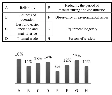
K. Value Standards and scaling them
After the analysis, the Value Engineering team determined the Value standards which would be the base for analyzing the best ideas. The following day, having reviewed the value standards in two binary methods, the workshop compared and evaluated them. The result of the evaluation was provided to the group and after the final opinion exchange the group reached final results as seen in fig. 1.
L. Analyzing the base plan according to the value standards
[image:3.612.65.303.515.601.2]After describing the base plan completely, removing the ambiguities and assuring that the whole group has the same definition about value standards, the group analyzed the base plan. The aim of this section was to discover the weak points of the plan and the possibility to increase the value. The group evaluated the plan to be efficient, as seen in fig. 2.
Table III- Index description of Fig. 1 and 2
Fig. 1. Evaluation of Value Standards
Land 650,000$ Construction, testing and commissioning
600,000$ Equipment 2,500,000$
Power transformer 700,000$
Designing and engineering
services
50,000$
Tender procedure, selecting the winner and exchanging the
contract
6 months Supply of transformers
12 months
Designing 4 months Constructional section
15 months Supply of equipment 12
months
Installing section
6 months
A Reliability E Reducing the period of manufacturing and construction B Easiness of
operation F Observance of environmental issues
C
Less and easier operation and maintenance
G Equipment longevity D Internal made H Personnel`s safety
[image:3.612.317.548.529.724.2]Fig. 2. The base plan analyze
IV. FUNCTION ANALYZING SYSTEM TECHNIQUE (FAST) Analyzing the functions and drawing the FAST (Function Analysis System Technique) diagram was defined as the core of Value Engineering technique and conducting it accurately has great influence on creativity and analyzing the expense of changing new ideas.
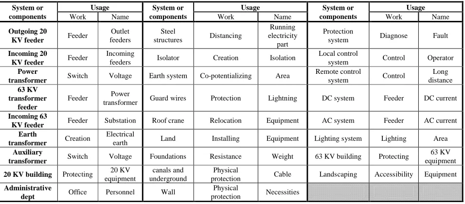
A. Function analyzing table
There are several ways to draw out the analyzing schedule of the operation, (From whole-to-detail or from detail-to-whole) The detail-to-whole classic method, in spite of its time consuming nature, would assure us about having all the aspects and operations. Thus in this workshop the group used this method and the operations schedule which provides the definition of main, secondary and supporting functions were presented by the consultant. The Table IV has been agreed upon by the whole group and has been considered as a base for drawing the diagram.
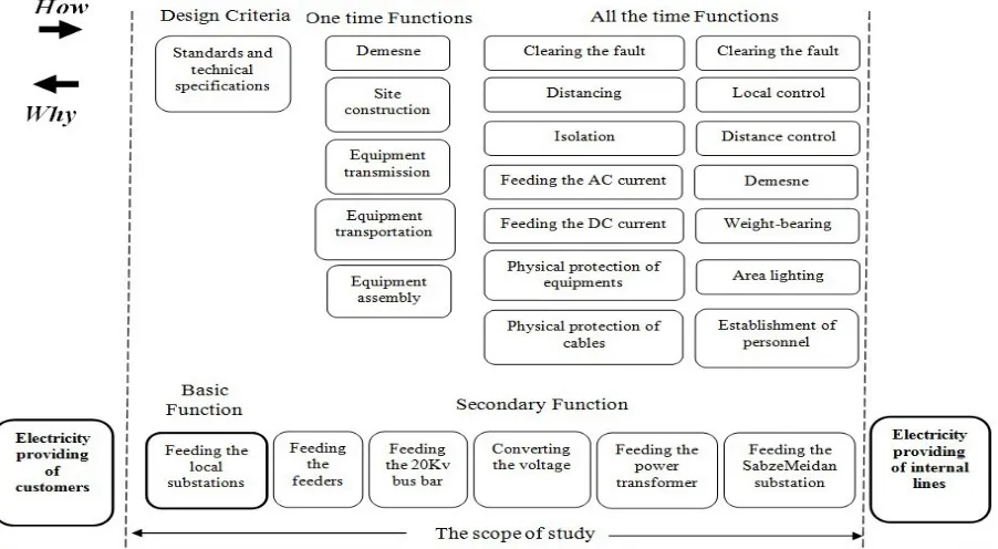
B. Drawing the FAST Diagram
Drawing the FAST diagram must be done after preparing the details of operation system schedule. In order to draw the diagram, the main and secondary operations would be identified by trying to answer two questions of How? and Why? and the relation between operations would be introduced.
The final purpose of the project is to provide the customers with electricity, and the main operation of the project was to feed the 20KV local substations.
FAST diagram in addition to showing all the main operations, basis for deciding the focused points in order to increase the
value of the project. These points were chosen according to two expensive operations in the FAST diagram and also the operations which have the great potential of changing.
V. CREATIVITY CYCLE,EVALUATION AND DEVELOPMENT A. Collective thinking and Theorization
The creativity phase is the most pleasant stage in Value Engineering workshop. In this phase, according to the FAST diagram which was derived from the previous phase the potential point of project has been determined. In order to reach the maximum efficiency at the beginning of the following day at the highest level of group preparation the phase of negotiating has been done in brainstorming method and 101 ideas were derived.
B. Selecting the primary ideas
After the creativity phase, each idea was evaluated and introduced in brief by the owner of the idea, and group members discussed as follows:
Is the idea practical?
Is enough information gathered for the idea?
Does that idea increase or decrease the cost?
Does the group agree to transfer the idea to the next phase and develop it?
After answering the aforesaid questions, the group discussed whether to agree on developing the idea or not. The scores are from 1 up to 5. "5" means that the group members are strictly willing to develop that idea and "1" means the idea has no value for developing and working on it would be waste of time.
After this process for the considered ideas, the votes were gathered and presented to the whole group. The group discussed again about the ideas which had great difference in their score for their development (Consist of 1 and 5 score) and reached a mutual idea. Finally 30 ideas were selected for the development phase and the working group for each idea has been selected.
System or components
Usage System or
components
Usage System or
components
Usage
Work Name Work Name Work Name
Outgoing 20
KV feeder Feeder
Outlet feeders
Steel
structures Distancing
Running electricity
part
Protection
system Diagnose Fault
Incoming 20
KV feeder Feeder
Incoming
feeders Isolator Creation Isolation
Local control
system Control Operator
Power
transformer Switch Voltage Earth system Co-potentializing Area
Remote control
system Control
Long distance 63 KV
transformer feeder
Feeder Power
transformer Guard wires Protection Lightning DC system Feeder DC current Incoming 63
KV feeder Feeder Substation Roof crane Relocation Equipment AC system Feeder AC current
Earth
transformer Creation
Electrical
earth Land Installing Equipment Lighting system Lighting Area
Auxiliary
transformer Switch Voltage Foundations Resistance Weight 63 KV building Protecting
63 KV equipment
20 KV building Protecting 20 KV
equipment
canals and underground
Physical
protection Cable Landscaping Accessibility Equipment Administrative
dept Office Personnel Wall
Physical
protection Necessities
[image:4.612.69.547.536.746.2]C. Finalizing the ideas
During a one-week gap between the two sections of the workshop each group developed their own ideas; they revisited the site and omitted impractical ideas. At last 10 superior ideas were presented to the workshop as follows:
1. Using the PASS system or hybrid ( With no change in 63KV bus bar arrangement)
2. Constructing the internal compact 63KV switchgear hybrid ( With no change in 63KV bus bar arrangement)
3. Constructing the 63KV switchgear with ordinary equipment
4. Using the underground for 20KV switchgear
5. Numeric control system and omitting the operator with no change in base plan
6. Numeric control system and omitting the operator, changing the layout of transformer and switchgear 7. Using the gas heating system
8. Transferring the 63KV switchgear to 230KV substation, connecting with 63KV cable in the whole way, feeding as feeder transformer
9. Four-breaker ring with GIS equipment 10. Indoor Installation of transformer
D. The results of evaluating the ideas
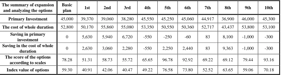
After evaluating the practical ideas, changes occurred in the layout of the equipment, the cost of each idea in detail, advantages and disadvantages, the changes happening with executing of each idea to value standards, assessment of the ideas according to the value standards in binary method in comparison to the base plan was conducted by the group.
In the Table V, the comparison of options with each other and with the base plan according to the lifetime cost beside the primary investment cost, and estimating the value standards and value index of the options according to the comments of the group members has been illustrated.
E. Superior options
Option 5: Using the numeric control system and omitting the operator
Option 6: Using numeric control system and omitting the operator, changing the layout of transformers and switchgear.
Option 8: Transferring the 63KV switchgear to 230KV substation, connecting with 63KV cable in the whole way, feeding the transformer as feeder transformer
Option 10: Indoor Installation of transformers F. Presenting the scenarios
The last section in Value Standard is combination of the superior options in order to use the maximum value of each option and reaching the highest value standards. In this way, the group combined the options which had the ability of combination and presented several scenarios to the client so that they can make the final decision. The Value Engineering group presented four scenarios combined together as follows:
[image:5.612.84.535.63.311.2]1) Scenario number one: Constructing the GIS according to the base plan and changing the ordinary control system to the numeric system in order to omit the operator and constructing the office building and indoor installation of transformers.
2) Scenario number two: Constructing the GIS substation by changing the layout and the ordinary control system to the numeric system in order to omit the operator, constructing the office building and indoor installation of transformers.
3) Scenario number three: Transferring the 63KV switchgear to 230KV substation, using 63KV cable in the whole way, feeding the indoor transformers as feeder transformer, distance controlling of transformers and 20KV cubicles in order to omit the operator.
4) Scenario number four: Transferring the 63KV switchgear to 230KV substation, using 63KV cable in the whole route and feeding the indoor transformers as feeder transformer.
G. Comparing the scenarios by their evaluation
[image:6.612.67.540.66.193.2]Economical comparison of the scenarios was simple. In the Table VI, primary investments and the saving in comparison to each other have been indicated.
VI. SUBMISSION PHASE A. Report submission meeting:
The report submission meeting took place in presence of top managers, deputies and experts of the REC, and the final report was presented.
B. Presenting opinions:
The participants enthusiastically discussed the advantages and disadvantages of each scenario and discussed the technical points and cost of the each superior scenario. Also some recommendations were presented to improve the project.
VII. CONCLUSION
As it was seen, the required land for this substation was not meeting our requirements and also the available resources for establishing a GIS substation were not enough.
The feeder lines were changed to cable type which was not as per the base plan and had lots of complexities. The instrumentation was time consuming and the deadlines were difficult to meet. In these conditions the project started to accomplish Value Engineering in REC and an introduction to Value Engineering workshop was conducted. The contractors of the project were worried about the elongation the time schedule and even delay in commissioning. Due to cost reduction and cost effectiveness policies, the client was worried about the final output.
With the commissioning of the cable throughout the feeder route, the problem of combination mode of feeders arose and additionally, installing the towers in some parts of the route encountered several limitations. The time schedule was reduced to 6 months from the base plan. The quality assurance, the workload and the functioning of the substation had increased in a feasible way. The saving in the primary investment was 769,980 $ and the lifetime cost was reduced by 1,146,300 $.
With the right decision of REC the Value Engineering processes was introduced to other upcoming projects which was a great success for Value Engineering.
REFERENCES
[1] Arthur E Mudge ."VALUE ENGINEERING " MCGRAW HIL 1981W [2] Arthur E Mudge."VALUE ENGINEERING A SYSTEMATIC
APPROACH" MCGRAW HIL1971
[3] S.S.Iyer, Value Engineering usage method, Jebel Ameli, Farat publication , 2004
[4] Tavakoli Reza, Shekari Amir, Value Engineering as a powerful tool, Tadbir journal, Number 132
The summary of expansion and analyzing the options
Basic
plan 1st 2nd 3rd 4th 5th 6th 7th 8th 9th 10th
Primary Investment 45,000 39,370 39,060 38,280 45,550 45,250 45,060 44,917 36,900 46,000 45,300
The cost of whole duration 52,800 50,170 55,860 55,080 53,350 50,550 50,360 52,717 43,437 53,800 53,100
Saving in primary
investment 0 5,630 5,940 6,720 -550 -250 -60 83 8,100 -1,000 -300
Saving in the cost of whole
duration 0 2,630 3,060 2,280 -550 2,250 2,440 83 9,363 -1,000 -300
The score of the options
according to scales 78.28 51.31 58.73 55.72 65.65 96.78 92.92 69.22 69.12 79.44 93.16
Index value of options 59.30 40.91 42.06 40.47 49.22 76.58 73.80 52.52 63.65 59.06 70.18
Equipment cost
Execution cost
Others cost
primary investment
Repairing cost
Operation cost
Whole life cost
Primary saving
Life duration saving
1st Scenario 25,850 6,200 13,500 45,550 4,800 500 50,850 -550 1,950
2nd Scenario 25,660 6,200 13,500 45,360 4,800 500 50,660 -360 2,140
3rd Scenario 19,820 5,980 11,500 37,300 5,000 -963 41,337 7,699 1,143
4th Scenario 19,820 5,580 11,500 36,900 5,000 1,537 43,437 8,100 9,363
[image:6.612.63.558.656.721.2]Table V- The comparison of options together and with the base plan