Abstract—The development procedure of permanent magnet drives for sensor less operation beginning from standstill under overload conditions has to consider different design aspects coevally. First, the robust rotor position sensing by test signal enforces a design with a strongly different behavior of the spatial dq-oriented differential inductance values. Therefore, the interior rotor magnet array arrangement is from principle predestinated for the controlled sensor less mode including standstill. Fortunately, in order to reduce costs, the distinct reluctance torque capability of such interior magnet arrangement is additionally used for a significantly increased torque by applying a pre-oriented stator current space vectors within the quasi-steady control.
Index Terms—Sensorless Vector Control, Machine Design, Inductance Modeling, Nonlinear Saturation Effects.
I. INTRODUCTION
The overall design process of modern high performance and cost effective permanent magnet drives is still a complex multi physic task, as shown in Fig 1. [1]. In order to achieve both a high efficiency and a simple controllability of the motor, many proposed designs have to be investigated systematically by the ‘virtual design’ approach based on manifold numerical commercial available simulation tools. Thereby, each drive design combines advantages and disadvantages with respect to the governing costs and desired performance [2].
During the electromagnetic machine, the electrical power converter and the software based control design process a lot of high sophisticated simulations take place in order to verify the desired performance behavior in advance [3]. The applied Finite Element method with directly coupled exter-nal electrical circuits is very beneficially for those tasks [4].
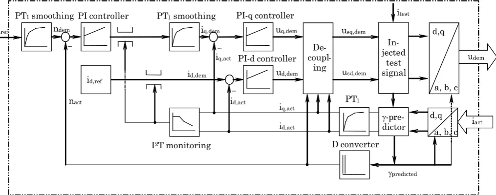
It takes implicit account of important geometric and crucial nonlinear magnetic properties of the machine, as well as the converter topology, which mainly govern the relevant drive performance aspects [5,6]. Moreover, the inclusion of basic control features within the circuit approach allows the simulation of the complete drive system in advance. A deeper insight into the 4.5 kW permanent magnet machine and the according power converter with the implemented control algorithm is given in Fig. 2, where the typical interior permanent magnet structure as well as the DC-link capacitors of the power module are obvious. The
1 Manuscript received April 8, 2009.
C. Grabner, J.V. Gragger, H. Kapeller, A. Haumer and C. Kral are with the Austrian Institute of Technology (AIT), business unit Electric Drive Technologies, Giefinggasse 2, 1210 Vienna, Austria, (e-mail: [email protected].)
rated values of machine and converter are partially listed in Table I and Table II.
Figure 1. Multi-physical design process of drives.
Figure 2. Typical interior permanent magnet machine construction (left) and power electronic with DC-link (right).
TABLEI MACHINE PROPERTIES
Rated power
Copper
losses Iron losses
Friction, fan losses
Remaining losses
[kW] [W] [W] [W] [W]
4.5 246 103 55 38
TABLEII CONVERTER PROPERTIES
Rated power
Pulse-frequency
Output current
Output
frequency Efficiency
[kVA] [kHz] [A] [Hz] [%]
5 2 14 0-200 95
C. Grabner, J.V. Gragger, H. Kapeller, A. Haumer and C. Kral
1Sensorless Permanent Magnet Drive Design
Proceedings of the World Congress on Engineering 2009 Vol III. SENSORLESS CONTROL MODE
The vector control mode operates the permanent magnet motor like a current source inverter driven machine applying a continuous current modulation [7]. Therefore, a very precise knowledge of the rotor position is necessary. This could be achieved by processing the response of the machine to arbitrarily injected high frequency test signals, whereby special anisotropic properties of the machines rotor are required. The vector control software itself is adapted to the hardware system depicted in Fig.2.
A. Nonlinear motor model
The practical realization of the control structure is for-tunately done within the rotor fixed (d,q) reference system, because the electrical stator quantities can there be seen to be constant within the steady operational state [8]. The stator voltage and flux linkage space vectors are therefore usually formulated in the (d,q) rotor reference frame as
whereby rs denotes the normalized stator resistance. The
inductance matrice is written as
It considers, e.g., only main inductance changes in the spatial d-direction due to the d-current component of the stator current space vector, whereas influences due to the q-current component are neglected in (3). With respect to the q-direction, the same aspects are valid in (3). Consequently, the relation (3) has a symmetrical diagonal shape, whereas cross-coupling effects due to saturation effects are omitted.
A further inclusion of some basic identities for the per-manent magnet flux space vector in the (d,q) system, namely
reduces the system (1), (2) and (3) to the simpler set of equations
Thereby, (5), (6) strictly distinguishes between main inductance values lSd, lSq, which are governing the rated
operational state, and the more sophisticated differential inductances
which are mainly influencing the voltage drops due to the
(d,q) related time-dependent current changes in (5), (6). It is thereby obviously from e.g. (7) that there is a direct vice-versa relation between the differential inductance lSd,diff and
the main inductance lSd, if the saturation dependency from
the d-current component is well known. With respect to sensor less drives, the properties (7), (8) are of main importance.
Unfortunately, both equations (5), (6) are always directly coupled without the exception of standstill. That fact is very unsuitable in particular for the design of the current controller. Thus, with regard to the used vector control topology, a more favorable rewritten form of (5), (6) as
with (7), (8) is commonly introduced.
B. Simplified block diagram of closed-loop control
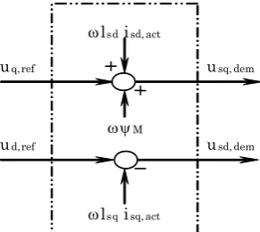
[image:2.595.356.502.391.521.2]The control schema in accordance to (9), (10) is realized by using the decoupling network of Fig. 3 in Fig. 4. with respect to the (d,q) axis notation as a two-step overlaid cascade structure [7, 8].
Figure 3. Block diagram of the decoupling-circuit.
The decoupling phenomena (9), (10) is build up with both fictive voltages ud, uq according to Fig.3. So, both (d,q) axes
related controller in (9), (10) can be adjusted independently from each other. The outer speed cascade allows adjusting a pre-set speed value ndef, after getting smoothed by a
PT1-element.
ud,ref
uq,ref usq,dem
usd,dem ωlsd isd,act
ωlsq isq,act ωψM (1)
(2)
(3)
(4)
(5)
(6)
(7)
(8)
(9)
Figure 4. Outline of important devices of the vector controlled permanent magnet motor by neglecting any feed-forward loops.
The output of the PI speed controller is also smoothed by a PT1-element and restricted by the thermal I2t-protection in order to avoid thermal damages. The PI speed controller has a moderate sampling rate and determines the demanded q-current component. In a simplified application, the drive is operated with a default zero d-current component in order to achieve maximal torque output. The actual measured electri-cal phase currents are transformed to the rotor fixed (d,q) reference system and continuously compared to the demanded d- and q-current components at the innermost current cascade structure. With regard to the d- and q-axis separation, the generated PI-current controller output voltages ud, uq are almost seen as fictive quantities in Fig.7,
from which the de-coupling-circuit given in Fig.6 calculates the real demanded stator voltage components usd, usq for the
normal operation afterwards.
C. Injected high frequency test signals
Test signals of very high frequency are superimposed to the demanded stator voltage components usd, usq and are
further treated within the power stack ASIC in order to generate the according space vectors in Fig. 4. Thereby, the desired current test signals itest are almost related in the
d-direction of the estimated (d’,q’) reference system of the given rotor in Fig. 4. Thereby the estimated (d’,q’) and the real (d,q) system could differ and hence, the difference is thereby treated by a PLL.
If the measured high frequency content of the q-current component of the PLL is zero, both systems (d’,q’) and (d,q) match. So, the position would be correctly estimated. But if there occurs also a d-current component due to the applied test vector in a wrong direction, a difference between (d’,q’) and (d,q) would occur. For the correctness of those algorithm it is essential, that the influence of the saturation dependent parameters (7),(8) of the machine are laying between safety limiting values.
III. SPACE-DEPENDENT INDUCTANCES
[image:3.595.346.515.413.563.2]Inductances are governed by various aspects, whereby the geometric properties and the occurring magnetic saturation of the lamination have a significant impact [9]. Moreover, the magnetic circuit is almost pre-saturated due to the inserted embedded permanent magnets. So, the main task is to set-up a straightforward numerical procedure for the evaluation of those equivalent circuit characteristics with the transient Finite Element approach. Thus, the inductances (7),(8) are derived indirectly from (d,q) space dependent flux-current characteristic.
Figure 5. Detail of the rotor design concerning stray fields.
St rang a
( )
u t St rang b St rang c
( )
i t
( )
i t 2
( )
i t 2
d q
I2T monitoring
id,act nact
PI-d controller
ud,dem
iact PT1smoothing PI controller
ndem iq,dem
nref
PI-q controller
uq,dem
iq,act
D converter
udem
usd,dem De
-coupl -ing
d,q
a, b, c
a, b, c d,q id,dem
id,ref
PT1smoothing
PT1
id,act iq,act
usq,dem
In -jected
test signal
γ-pre -dictor
γpredicted itest Proceedings of the World Congress on Engineering 2009 Vol I
Figure 6. Standstill set-up for the determination of saturable main and differential q-inductances of a electrical two-pole machine.
St rang a
( )
u t St rang b St rang c
( )
i t
( )
i t 2
( )
i t 2
d
q
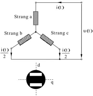
Figure 7. Standstill set-up for the determination of saturable main and differential d-inductances taking account also account of the joke saturation due to the embedded magnets of a electrical two-pole machine.
The proposed origin design of flux barriers between the magnets shown in Fig. 5 influences the previous parameters (7),(8) as well as the torque output and therefore also the drive performance.
The desired ratio between both inductances (7),(8) can be obtained by the choice of the air gap length, the degree of coverage of the permanent magnets based on the pole pitch of the machine, and the flux barriers between the poles [10,11]. With respect to mechanical aspects circular ends are always favorable in Fig. 5. An optimum distance between the rotor surface and the hole of the magnets has to stand with the mechanical strength and the magnetic saturation. The sheet thickness of the laminated is the smallest possible distance. A smaller distance results in problems with the punching process of the lamina [12].
A. Set-up for the saturation dependent differential inductances evaluation
The saturation dependent values of (7) have to evaluated in advance with respect to the spatial directions in order to verify the robustness of the drive. In particular the sensor less mode at standstill even at very high currents, which are e.g. necessary for a high pull-out torque have thereby to be covered. If the known q-axis of the rotor is aligned with the q-axis of the stator current space vector, no effect due to the permanent magnet flux (4) in the q-axis has to be considered under those assumptions (3). The relations (7) are therefore valid. The pre-saturation of the lamination due to the magnets is indirectly considered.
Neglecting slotting effects, the necessary flux-current characteristic in the q-axis in (2), the proposed machine design is treated within the numerical simulation by Finite Elements as a single phase test set-up as shown in Fig. 6.
If the system is simply fed by a sinusoidal time-dependent
voltage, the obtained time-dependent current consumption is mainly non-sinusoidal due to the iron saturation. But the courses are symmetrical to the abscissa.
Contrarily, if the d-axis of rotor coincides with the d-axis of the stator current space vector in Fig. 7, the numerical calculated time dependency of the d-current inside the machine represents a non-sinusoidal course with a constant offset, caused by the magnetized magnets within the lamination.
B. Saturation (d,q)-dependent differential inductances and main synchronous inductances
With the aid of commercial numerical field calculation tools, the obtained flux-current relation (3) and consequently the differential and the main inductance (7) courses are straightforward derived with respect to the (d,q) notation as shown in Fig. 8 and Fig. 9. Thereby, saturation within higher current magnitudes enforces that both d- and q-characteristics become very similar, which means, that the test signals response is equal in each direction and no distinction could be achievable.
[image:4.595.310.551.436.561.2]The dependency of the main inductance shown in Fig. 9 shows along the complete current range a distinct difference. Thereby, both relations (7),(8) could be clearly verified. The previous desired reluctance effects due to different d- and q-inductance values over the complete current magnitude in Fig. 9 are fortunately usable even for full- or overload capabilities.
[image:4.595.308.551.612.743.2]Figure 8. Dependency of d-axis differential inductance from d-current (red) and q-axis differential inductance from q-current (blue).
IV. RATED OPERATIONAL STATE
The design of the drive is completely done with the aid of a transient Finite Element analysis with directly coupled externally circuits considering control features in a very straightforward way. Due to the unskewed machine, only a 2D modeling is recommended. The analysis takes fortunately account of geometric as well as magnetic nonlinear material properties. Thus, saturation impacts to the torque generation are fully covered.
In case of the quasi-steady operational state, the implemented control (1) to (10) could be modeled by numerical methods in a very simple manner. The usage of a sinusoidal current fed numerical model covers the innermost layer of Fig. 4 sufficiently. Thereby, the rotor revolves in the numerical Finite Element simulation with constant default speed. Attention has to be given to the almost known spatial phase angle of the (d,q) rotor system and the space current distribution in the stator. A isq current component produces
torque and a negative isd current component enforces
additional field weakening. Due to reluctance effects, the negative isd component also produces a reluctance torque
[image:5.595.68.263.339.497.2]component.
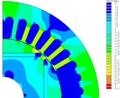
Figure 10. Flux density plot with linear color scaling up to 3.1 T for the machine at the nominal operating point.
Figure 11. Torque versus load angle of the drive. The red line presents the synchronous torque and the blue line the sum of the synchronous torque
and the reluctance torque.
The voltages and torque magnitudes are obtained as output from the numerical analysis. Moreover, associated field plots, such as exemplarity shown in Fig. 10 depicted for distinct time-steps give a good insight into the magnetic
utilization. However, undesired higher current harmonics are not covered within the current feed model and could therefore not appear within the simulation. However, within interior magnet structures those effects are almost of secondary interest because of their relatively high inductance values. Thus a current excitation could be applied at the machine terminals with respect to the (d,q) reference system.
A. Torque building isq current component only
The standard control algorithm of the permanent magnet motor uses only the isq current in the spatial q-axis for the
torque control. The magnetic utilization of the proposed design in Fig. 5, which fulfills the test signal requirements concerning the differential inductances, is exemplarily given in Fig. 10. A modified algorithm applied for salient pole rotors uses pre-oriented stator space current vectors in the machines with additional negative d-axis current to produce additional reluctance torque.
B. Performance increase by reluctance torque due to negative isd currents
The derived torque can be increased by applying field weakening isd current components to the proposed rotor
design with strong anisotropic behaviors as it is the case within embedded permanent magnets.
The relevant load-angle characteristics of Fig. 11 are simply obtained from numerical simulations in advance under the circumstances that the rotor is fixed and the stator space vector rotates continuously. Effects due to saturation are thereby fully covered.
The conditions to maximize and optimize the torque-to-current ratio of an interior permanent magnet motor are found from several analyses, where more complex parameter variations have to take place.
The maximum torque of the motor in Fig. 11 is nearly 30 Nm. The reluctance torque produced due to the unequal main inductances of the direct and quadrature axis of the machine is shown in Fig. 9 and could be found to be about 15% of the maximum torque at the pre-angle of 30 electrical degrees. Thus, a shifting of the rotating constant current space vector in the implemented control of Fig. 4 for about 30 electrical degrees ahead from the standard 90 grad approach causes a significant additional torque output.
V. CONCLUSION
The design of permanent magnet drives for sensor less operation has to consider different aspects. First, the robust sensing capability of test signals enforces different differential inductances with respect to the (d,q) notation. The influence of occurring saturation to that behavior has to be restricted.
In order to improve the torque output due to the usage of the reluctance torque, the anisotropic inductance properties should be significantly different.
Thus, a negative d-axis current increases thereby the effective torque of the motor up to e.g. 15%.
[image:5.595.44.288.546.691.2]Moreover, several secondary effect, such as cogging torque, torque ripple, non-sinusoidal shape of no-load voltage and losses, which are worsening the performance of such innovative drives, must be restricted to limiting values.
Thus, a coupled transient electromagnetic-mechanical finite element calculation method with directly coupled external circuits is useful, in the case of the voltage waveform, torque ripple and additional losses. The influence of higher harmonics on the design steps becomes visible by this method.
REFERENCES
[1] W. Nowotny and T.A. Lipo, Vector control and dynamics of AC
drives, Clarendon Press: Oxford, 2000.
[2] Hendershot JR, Miller TJE.: Design of Brushless Permanent Magnet Motors. Oxford: Oxford University Press, 1994.
[3] K.G. Bush, Regelbare Elektroantriebe: Antriebsmethoden,
Betriebssicherheit, Instandhaltung, Verlag Pflaum: München, 1998.
[4] Salon J.S.: Finite element analysis of electrical machines. Cambridge: Cambridge University Press, 1996.
[5] Davat B., Ren Z., Lajoic-Mazenc M.: The movement in field modeling. IEEE Transactions on Magnetics, Vol.21, No.6, 1985. [6] Kohnke P.: Theory reference released version 6.1. Ansys Inc.,
Canonsburg, USA, April 2002.
[7] P. Vas, Electrical machines and drives: A space-vector theory
approach, Clarendon Press: Oxford, 1996.
[8] P. Vas, Vector control of AC machines, Oxford University Press: Oxford, 1990.
[9] P. Vas, Parameter estimation, condition monitoring, and diagnosis
of electrical machines, Clarendon Press: Oxford, 1993.
[10] Domack S.: Auslegung und Optimierung von permanent- erregten Synchronmaschinen mittels Steuerverfahren und der Methode der finiten Elemente. Aachen: Verlag Shaker, 1994.
[11] Kiyoumarsi A., Moallem M.: Optimal Shape Design of Interior Permanent-Magnet Synchronous Motor. IEEE Conference on Electric Machines and Drives, page 642-648, 2005.