Abstract — Pulsed neutron beams available at the ISIS
spallation source offer diverse possibilities for materials characterization using diffraction and imaging. In this paper we review a range of applications of the time-of-flight neutron diffraction for the characterization of phase transformations and residual stress states in industrially-relevant situations. The setup of the ENGIN-X instrument at ISIS is described, followed by a series of case studies based on the recently obtained results.
Index Terms — neutron time-of-flight diffraction, residual
stress, phase transformation, strain tomography.
I. INTRODUCTION
Human creativity often finds material manifestation. Sculpture and architecture are the examples that are most obvious, but both haute couture and automobile design also belong to this list. These creative activities depend crucially on the choice and knowledge of materials used to ensure particular properties of the assemblies, from external appearance to environmental performance. The ability to control and re-shape the surrounding material world is an important feature of human civilization. Ideas find their embodiment in wood or stone, metal or plastic.
All load-bearing structures experience deformation, and sustain stress. Stress, the measure of force per unit area, is a central concept in engineering design. In most cases stress is inhomogeneous, as required by the geometry of assemblies and performance optimization. Stress is difficult to measure directly, but can be calculated from measured strains.
Strain, in engineering terms, is defined as the ratio of elongation to initial length, or the relative change of angle
Manuscript received April 30, 2009.
Shu Yan Zhang and Evelyn Godfrey are with ISIS, Science and Technology Facilities Council, Rutherford Appleton Laboratory, Chilton Didcot, Oxfordshire, UK (e-mail: [email protected]).
Brian Abbey is with the Department of Engineering Science, University of Oxford, Oxford OX1 3PJ, UK
Pingguang Xu, Yo Tomota are with the Quantum Beam Science Directorate, Japan Atomic Energy Agency, 2-4 Shirane Shirakata, Tokai-mura, Naka-gun, Ibaraki, 319-1195, Japan
David Liljedahl, Olivier Zanellato and Michael Fitzpatrick are with The Faculty of Mathematics, Computing and Technology, Open University, Milton Keynes, UK
Joe Kelleher is with the School of Materials, University of Manchester, Manchester, UK
Salvatore Siano is with Istituto di Fisica Applicata 'Nello Carrara'—CNR, Via Madonna del Piano snc (ed. C), 50019 Sesto Fiorentino, Italy
Javier Santisteban is with Laboratorio de Fisica de Neutrones, Centro Atomico Bariloche (R8402AGP) San Carlos de Bariloche, Argentina
Alexander M. Korsunsky is with the Department of Engineering Science, University of Oxford, Oxford OX1 3PJ, UK
due to shear. A variety of strain measurement techniques has evolved over decades, and is widely employed in experimental studies of deformation behaviour of materials and structures. The aim of strain measurement is to characterise the response to applied loads, particularly such that correspond to in-service loading, and to observe the response of objects so as to predict the integrity of various designs. This is the principal purpose of strain analysis for structural design [1].
At small applied strains (below about a percent) most materials respond linearly and elastically, i.e. return to the original shape and dimensions after load is removed, and in such a way the observed strain is proportional to the applied load (linear response). This is described mathematically by the generalised Hooke’s law. Permanent inelastic deformation takes place at higher strains and stresses. Irreversible deformation can be caused by material damage (associated with the creation of microscopic or macroscopic discontinuities and voids), or by permanent change of shape without significant change of volume (associated with the relative shear of constituent material sub-volumes with respect to each other, termed “plasticity”). Plastic deformation can be further described as time-independent (instantaneous) and time-dependent (creep).
In the most general case, the material’s strain response to applied load can be described by elastic-plastic constitutive law with damage. Due to the non-linear nature of deformation, at each loading step the material response depends on the previous deformation history, so that incremental form of constitutive law must be used that relates strain increment to the applied load and current material state (strain and damage). The key function of the constitutive law that describes the material response is to separate the total strain increment into the elastic and inelastic parts: the elastic part is reversible and related to stress via Hooke’s law, while the inelastic part is irreversible and does not induce stress.
Most strain measurement methods are only capable of measuring total strain increments. This is due to the fact that strain measurement is usually accomplished by monitoring the change of distance between reference points associated with markers placed on the surface or embedded in the bulk of the material. This distance is affected by both the elastic and inelastic parts of strain. Examples of experimental techniques include contact methods, such as clip gauges or resistive strain gauges [2], and non-contact methods, such as photogrammetry (measurement of displacements of visible grids on sample surface), Moiré interferometry methods that make use of reflective gratings deposited on sample surface
Materials Structure and Strain Analysis Using
Time-of-flight Neutron Diffraction
Shu Yan Zhang
,Evelyn Godfrey
,Brian Abbey, Pingguang Xu, Yo Tomota, David Liljedahl,
[3], and Digital Image Correlation (DIC) methods [4]. The particular significance of neutron and x-ray diffraction methods is that they offer a direct method of measuring the elastic component of strain deep within crystalline materials through the precise characterisation of the interplanar crystal lattice spacing. In contrast with the other methods mentioned above, diffraction uses the atomic lattice itself as a deformation gauge. This makes the methods sensitive only to elastic strains, as inelastic strain mechanisms do not induce changes in interplanar lattice spacing: plasticity causes lattice plane shear, while damage causes voiding i.e. lattice plane separation (to distances that far exceed the original spacing). Since stress is directly related to elastic strain, with the knowledge of the material stiffness, diffraction thus provides a highly precise, spatially and directionally resolved means of stress evaluation. Thanks to its stress evaluation capability, diffraction has become an increasingly important tool in engineering. Since most criteria of integrity and failure in structural engineering use stress as the key parameter, diffraction methods have become useful in predicting the durability of components, optimising design and improving performance. The unique non-destructive nature of this measurement technique is particularly beneficial in the context of engineering design, since it allows the evaluation of a variety of structural and deformational parameters inside real components without material removal, or at worst with minimal interference. Further, the combination of rapid data collection with good penetration depths allows in situ, real time, spatially resolved strain measurement (mapping) under the conditions representative of those that might be experienced in service.
The principle of diffraction strain measurement in polycrystalline alloys relies on Bragg’s law that establishes the relationship between the average interplanar lattice spacing d within the measurement gauge volume:
λ
θ
=
sin
2
d
(1) where, λ is the wavelength; d is the inter-planar spacing; Θ is one half of the angle through which the incident beam is diffracted by a particular family of planes.When a polycrystalline aggregate deforms elastically, the interplanar spacing within constituent grains changes. Within a set of planes that have similar orientation with respect to the stress direction, the interplanar spacing is similar between one grain and another. This grain-set-specific strain causes observable shifts of powder-like diffraction peaks, i.e. peaks obtained from the superposition of reflections from multiple grains. The average values of lattice spacing extracted from diffraction peak analysis are then compared to the spacing of the same planes measured in an unstressed sample d0.
Average elastic lattice strain ε can be found from the deformed lattice spacing d using the fundamental equation:
0 0
0
)
(
d
d
d
d
d
Δ
=
−
=
ε
(2)The case studies below represent contributions from different research groups that make use of the neutron diffraction capabilities of ENGIN-X at ISIS. The overview begins with the discussion of the experimental capabilities of the ENGIN-X instrument.
II. DESCRIPTION OF THE ENGIN-X INSTRUMENT AT ISIS
The ENGIN-X instrument at ISIS is a world leading neutron diffractometer purpose-built for stress evaluation in the context of materials engineering and research. ENGIN-X is very popular and used extensively by both engineers and materials scientists. Measurements are carried out in collaborative experiments between universities, industry and ISIS to address a wide range of engineering problems: new welding technologies for airframe manufacturing, fatigue crack initiation and propagation in composite materials, thermal cycling of materials used in the power generation industry, the development of strain measurement standards, etc. Because the method is non-destructive and ENGIN-X is able to accommodate large intact objects, archaeological materials scientists, conservators, and technical art historians also find that the instrument provides them with data on metal artefacts that they could not acquire by conventional means. The alternative, traditional methods of microstructure determination require invasive sampling. Because of this, strain and tensile tests for example have in the past very rarely been done on archaeological and historic objects.
ENGIN-X has a sample mounting stage allowing samples weighting up to one tonne to be accurately positioned within the measurement point with the accuracy better than 10 μm. Moving and rotating the sample within the neutron beam allows spatial and directional maps of strain to be built up. With the large sample mounting space, ENGIN-X provides the flexibility for the users to bring their own ancillary devices, such as welding rigs to perform real-time strain measurements during joining. ENGIN-X also has an in situ mountable servo-hydraulic stress rig that can apply up to 100kN tensile or compressive cyclic loads. The rig is equipped with a furnace and a cryogenic chamber that allow the sample to be maintained at temperatures from -200ºC to 1100ºC within normal atmosphere or under inert gas.
With regard to archaeological applications, of course a sample from an actual ancient or historical object cannot be subjected to these conditions. Instead, the chemical composition of metal object first has to be characterised, then replicas produced of the same composition and dimensions (in particular, thickness). The replicas must be formed in the way(s) that the original was likely to be produced, e.g. casting, hammering, fire-welding. The likely manufacturing method of an artefact is normally determined by investigative conservation. The replicas can then be tested under different environments, and the results used to discuss the probably properties of the original object. Diffraction measurements without sample environment can be carried out on the actual artefact, although it is important to have comparative replica measurements too, as all early metal objects are effectively ‘unknown’ samples, each made individually in the days before industrial standardisation. An art or archaeological object has to be mounted securely, by a conservator, in order for it to be rotated on ENGIN-X during analysis.
ENGIN-X consists of the following steps: 1) generate a 3D model of the sample using the CMM or the laser scanning arm; 2) position the sample on the sample stage using either the positioning table or the robotic arm; 3) locate the sample model in the virtual laboratory using SScanSS and specify the measurement position on the model; 4) carry out the measurement sequence using an automatically generated machine control script.
When the gauge volume is rastered across the sample, then one-, two- or three-dimensional representations of the measured quantities can be created, i.e. the neutron diffraction is used for imaging in the scanning or mapping mode, or for 3D tomographic reconstruction. In the case of strain mapping, the quantity being imaged is not a scalar, nor even a vector, but a second order tensor. This presents interesting challenges both in terms of the elaboration of the reconstruction algorithms, and the representation of the results. A technique referred to as strain tomography [6-7] is being actively developed at present.
Advanced measurement tools achieve greatest utility when they are closely coupled with interpretation and modelling. The design of experiments at ENGIN-X and the interpretation of the data obtained is closely linked to the advanced modelling capabilities of collaborating groups, including such techniques as finite element modelling, discrete dislocation dynamics, and atomistic simulations.
A key interpretation capability at ENGIN-X is the use of diffraction pattern refinement (Rietveld or Pawley) [8], that allows the determination of the average macroscopic elastic strain. The fundamental principle of this approach is model-based matching of the predicted diffraction pattern to the measurement. This kind of inverse problem methodology is effective in many applications. One development of particular relevance to residual stress analysis in engineering structures is the use of inverse eigenstrain methodology [9], a kind of “continuum mechanics Rietveld refinement” for residual stress analysis. It allows the reconstruction of the complete residual stress state on the basis of a finite number of strain measurements at discrete points.
A comprehensive introduction to the neutron strain scanning technique can be found in Hutchings et al.[10]. A description of the state-of-the-art in stress measurement using neutron and synchrotron radiation is contained in Fitzpatrick and Lodini [11]. More information about ENGIN-X can be found in Santisteban et al.[12].
Measurement arrangements and experimental studies described below are selected from the wide range of investigations carried out on ENGIN-X over the past year. The selection demonstrates the capabilities of ENGIN-X in a variety of different contexts and areas of research.
III. CASE STUDY – HIGH TEMPERATURE
DEFORMATION-INDUCED FERRITE TRANSFORMATION IN LOW ALLOY STEELS
Ultrafine grained steels are one of the most important research topics because of their good strength-toughness balance, wide potential applications and excellent material recyclability [13-14]. The deformation-induced ferrite transformation is well known as one of the most economical
ways to refine the microstructures of modern high strength low alloy steels. The effects of deformation temperature, strain and strain rate on dynamic ferrite transformation during hot deformation have been investigated in the last decade indirectly, whereby the microstructure is examined after interrupting hot deformation at different strains, and quenching deformed specimens [15-16]. However, no direct or quantitative crystallographic data has been reported on the in situ microstructure evolution during hot deformation.
Since neutron beams possess strong penetration ability due to the direct interaction with the atomic nuclei, the neutron diffraction technique is a powerful in situ material characterization tool even for relatively large samples of heavy elements. This property of neutron beams enables us to investigate the microstructure evolution behaviours in a non-destructive way under different environments involving phase transformations [17-18], bulk texture evolution [19], heterogeneous elastic/plastic deformation [20], dynamic recrystallization [21-22], etc. In the case study described here the in situ Time-Of-Flight (TOF) neutron diffraction was applied directly to investigate the dynamic ferrite transformations at a low strain rate during hot deformation at different temperatures, and to clarify the difference in static ferrite transformation and dynamic ferrite transformation
Temperature
Gas cooling 900°C, 20min
2min holding Unloading
t =720°C, 680°C, 640°C, 600°C
1°C/s
Time 0% or 50% compression
Fig.1 Schematic illustration for the temperature control and hot deformation process [23].
The sample material was a low alloy steel (2% Mn and 0.2% C by weight) in the as-quenched condition. The temperature control and the hot deformation processing history are shown in Fig.1. The first sample was heated to 900ºC for 20 minutes (stage 1), and then rapid gas cooling was used to achieve the cooling rate of 1 K s-1 to the desired temperature, e.g. 600ºC
(stage 2). Finally, the specimen was compressed at the strain rate of 1×10⁻³ s-1 (stage 3). Diffraction patterns were
recorded throughout this processing history. The second sample first followed the same heat treatment procedure (stages 1 and 2), but then in stage 3 the sample was isothermally held without being compressed. Three different samples were subjected to this kind of processing history, with different holding temperatures in stage 3. The ferrite volume fraction was calculated by using the Rietveld method taking into consideration the effect of deformation texture.
Fig. 2 shows the effect of compressive deformation on the isothermal ferrite transformation at different temperatures. If no hot deformation is applied, the ferrite volume fraction increases gradually with increasing isothermal hold time, and the static ferrite transformation is accelerated evidently by lowering the holding temperature. In the case of hot deformation, it is found that it promotes the ferrite transformation in the dual phase region (600ºC, 640ºC, and 680ºC) as well as in the single phase austenite region (720ºC), i.e. the occurrence of dynamic ferrite transformation has been confirmed at different transformation temperatures. In addition, an interesting phenomenon about the isothermal ferrite transformation is that at the beginning of hot deformation, the accelerating effect of hot deformation on ferrite transformation at 640ºC is more remarkable than that at 680ºC. At the end of hot deformation, the increase in ferrite amount at 640ºC becomes smaller than that at 680ºC.
Such changes in the dynamic ferrite transformation kinetics are believed to be related to the carbon concentration and the volume fraction of austenite, the transformation driving force, and the heterogeneity of plastic deformation. In order to achieve clearer understanding, dynamic crystallographic orientation analysis during hot deformation was thought to be necessary. Orientation analysis based on the inverse pole figure showed that the {110}<001> and {001}<110> preferred orientations of austenite and ferrite grains, respectively, is gradually formed during hot deformation, and that the austenite grains of the {110}<001> orientation preferentially transform to ferrite. The observed decrease in the transformation rate at 640ºC at higher strain is mostly related to the fact that carbon enrichment of the austenite leads to its hardening, so that the amount of plastic deformation in austenite is decreased, and the above effect is attenuated.
The case study considered above demonstrates how the exceptional capabilities of ENGIN-X allow extensive characterisation of the complex material system in situ during thermo-mechanical processing. TOF neutron diffraction was found to be particularly well-suited for simultaneous analysis of quantitative phase composition and preferred orientation (texture), and also their evolution. This combination provided the basis for developing improved insight into a material of great importance to applications and industry.
IV. CASE STUDY– ANALYSIS OF RESIDUAL STRESSES AT CRUISING ALTITUDE TEMPERATURE IN HYBRID AEROSPACE
STRUCTURES
Until recently, there has been a little capability for in situ diffraction studies of mechanical behaviour at temperatures below ambient [24]. Due to the recent marked progress in cryogenic technologies, there has been a growing demand for investigations of material mechanical behaviour at cryogenic temperatures. Applications include cryogenic texture processing of zirconium nuclear alloys, strain sensitivity of superconducting magnet wires, cryogenic structural steels and low temperature shape memory alloys for space applications. To address this area, a novel cryogenic experimental device has been developed and implemented on ENGIN-X, consisting of a vacuum chamber with cooling provided by a closed cycle refrigerator (CCRs) down to −200ºC in samples under applied loads of up to 100kN [25]. In the case study described here, the measurement was at -50ºC, the temperature representative of the cruising altitude conditions for large civil aircraft, to investigate the adhesively bonded reinforcement in order to improve the damage tolerance characteristics of hybrid aerospace structures.
Fig. 3 Residual stress in the CT(S) 3.5 mm below the bonded interface
New designs of integral metallic structures for aircraft will lack the inherent ‘crack stopping’ features as bolting and riveting is replaced by welding technologies. New methods to ensure the fatigue damage tolerance of such structures include the bonding of selective reinforcement patches to act as crack retarders. Crack retarders have been shown to be effective, but the mismatch of coefficient of thermal expansion between the reinforcement and the aluminium skin causes tensile residual stresses in the metal parts which might decrease the overall fatigue resistance.
The measurement and modelling results of the strain in the direction of the notch can be seen in Fig 3. It was found that linear model could accurately be used to assess the residual stresses at both room temperature and at –50ºC. The residual stresses were found to be about 40 MPa at room temperature and about 70 MPa at –50ºC. ENGIN-X has once again proved to be an excellent tool in the assessments of new material concepts. Further details of this work can be found elsewhere [26].
V. CASE STUDY –THE INFLUENCE OF WELDING PROCEDURES ON RESIDUAL STRESS STATES
Welding is an important industrial joining process, and over the years many different “flavours” of this method have been proposed. During the welding process, the joint undergoes a complex thermomechanical cycle during cooling. Of particular concern is the formation of tensile residual stress in the weld, which results mainly from thermal contraction as the filler metal cools and hardens. Where several passes are made, a pass may partially relieve the stress in previous passes, creating a complex stress state.
[image:5.595.307.556.323.639.2]Fig. 4: Strain in the longitudinal direction of a conventional austenitic steel weld made with 5 passes and a similar weld made with 8 passes.
Fig. 4 shows longitudinal strain in two grade 304 stainless steel welds. One weld comprises five passes of weld bead to partially fill a groove in a plate [27], the other weld having eight such passes to completely fill the groove. Additionally, the welding process was stopped and restarted twice during the fifth pass in each sample. First was a ‘ramped’ stop-start, where the welding power was reduced to zero over a 10 mm length, which was covered again when the welding continued. Secondly, an ‘abrupt’ stop-start was made by immediately stopping and later restarting the weld.
Although the 8-pass weld was thicker, it was expected that the elastic strains would be lower than in the 5-pass weld, as the final passes would anneal the effect of previous passes. Away from the abrupt stop-start, this is found to be the case. The 8-pass weld has relieved the strain at the ramped stop-start but intensified the strain at the abrupt stop-start. This is attributed to the additional thermomechanical cycling at this point making the material harder, and more resistant to the annealing from subsequent passes that occurs elsewhere. The results highlight the need to rigorously specify welding procedures. With experimental results for a given weld, these
could predict the effect of changing welding parameters such as the number of passes or the start and stop rates.
VI. CASE STUDY –ANALYSIS OF WELDS IN AEROENGINE STRUCTURES
In aeroengine manufacturing welding is used widely for the fabrication of shell-like structures such as casings and liners, and in the assembly of compressor and turbine components. Alongside conventional TIG welding, laser welding and friction welding are increasingly used, due to the ability of these methods to join dissimilar materials and to avoid material melting, thus reducing the probability of creating defects that may promote crack initiation and propagation. When post-weld heat treatment is applied, there is also the possibility of reducing the “frozen-in” residual stresses usually associated with the bond region and the thermo-mechanically affected zone (TMAZ). Quantification of the residual stresses is an important requirement for improving the design and reliability of the components being joined.
a)
b)
Fig.5: (a) Schematic diagram of the inertia friction welded high pressure compressor drum – drive cone (DDC) assembly. The circumferential weld line is indicated by the arrow. (b) Illustration of the residual stress map in the DDC in the final post-weld heat treated condition.
[image:5.595.59.278.336.477.2]reconstruction of the complete residual stress state within the sample [28]. The knowledge of the underlying eigenstrain distributions then allows the solution to be scaled up to obtain a representation of the residual stress state in the full scale assembly. Furthermore, subsequent stress relaxation due to creep during post-weld heat treatment can be readily modelled using finite elements. Fig.5b illustrates the computed residual stress state in the full scale assembly following post-weld machining and heat treatment. The predictions have been validated by comparison against various means of residual stress evaluation, including diffraction and hole drilling.
The study described provides an example of a validated experimental stress analysis approach for structural design of aeroengine assemblies. The combination of experimental strain measurements by TOF neutron diffraction with eigenstrain reconstruction allows complete characterization of the residual stress state, and simulation of subsequent system response to heat treatment and mechanical loading.
VII. CASE STUDY – THE USE OF STRAIN ANALYSIS TO IDENTIFY MANUFACTURING TECHNIQUES IN ETRUSCAN
BRONZE ARTEFACTS
[image:6.595.304.552.399.486.2]Siano et al [29] studied five archaeological copper alloy objects dated from the 8th to the 4th centuries BC from the Marches National Museum of Archaeology, Ancona, Italy, using X-ray radiography and neutron diffraction (texture and phase analysis on the ROTAX instrument at ISIS) and microstrain measurement on ENGIN-X. The objects, shown in Fig.6, were 1. a double handle from a situla (bucket); 2. a torc (an object-type that can be interpreted as a neck ornament or a trade-ingot); 3. & 4. bow-fibulae (dress fasteners) and; 5. a bracelet.
Fig. 6: The objects under investigation, from the Marches National Museum of Archaeology, Ancona
ENGIN-X microstrain measurements were performed at points on the situla handle and on the torc, using diffraction and transmission set-ups. The radial scans on the situla handle revealed broad peaks with a flat top and a marked texture effect, as evidenced by irregular peak intensities. The peak intensity ratios were fairly constant throughout the scan, which indicated that the preferred orientation was the same. This is compatible with a cube texture that is associated with
the typical columnar structure that occurs perpendicularly to the surface of the mould into which the metal is cast. Such a feature was not present in the brazing zone of the handle, which showed random crystal orientation.
In transmission, the handle displayed very distorted spectra, which were composed of several ‘single-crystal’-like contributions, confirming again the presence of a preferred orientation. The brazing on the other hand showed ‘normal’ Bragg edges. In the case of the torc, all pixels in the transmission set-up showed the characteristic Bragg edges that appear in polycrystalline specimens, with only minor departures from an isotropic theoretical transmission. This is indicative of only a very small (or negligible) degree of preferred orientation.
A strain map of a selected region around the middle of the torc was calculated by analysis of the Bragg edge shifts (Fig 7). An inhomogeneous microstrain distribution was found, that is clear evidence of residual stresses originating from cold deformation of the torc during the final working manufacturing step. Two microstrain profiles along orthogonal directions were also measured where the contribution of eventual plastic deformations due to use was probably negligible. The ‘powder’- like spectra seen in this case allowed the derivation of the microstrain profiles. Opposite double-phase modulations were observed along the axial and hoop directions. This is a typical indication of cold bending.
[image:6.595.48.289.473.636.2]
Fig. 7: Residual stresses in the necklace bar: (a) a map of the average microstrains through the bar (site T2), determined by analysing the Bragg edge shifts (transmission set-up); (b) two orthogonal microstrain profiles in a lateral zone of the bar (T3), determined by analysing the shifts of the diffraction peaks [29]
rather than plastic. This contrasted with the result for the bracelet. Thus the outwardly similar curved shapes of the handle, the torc, and the bracelet were produced by the ancient metalworkers employing three different sets of procedures.
VIII. CASE STUDY – NEUTRON BRAGG EDGE STRAIN TOMOGRAPHY USING
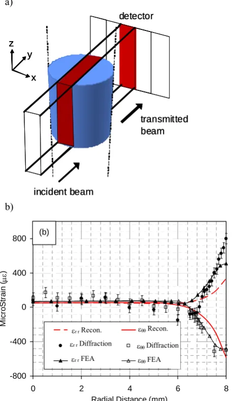
Due to the penetration ability and absorption and scattering properties of neutron beams, neutron imaging is now considered an essential tool in many branches of modern material science and engineering, as well as geology, archaeology etc. [30]. A new approach based on energy selective neutron imaging was recently developed using different experimental setups and was able to gather information about the material properties that cannot be obtained in other traditional diffraction modes. Here we present a brief overview of the concept of strain tomography using energy-selective (Bragg edge) transmission measurements (Fig. 8a).
a)
incident beam
transmitted beam detector
x y z
incident beam
transmitted beam detector
x y z
x y z
b)
-800 -400 0 400 800
0 2 4 6 8
Radial Distance (mm)
M
ic
roS
tr
ai
n (
με
)
εθθDiffraction εθθFEA εr rDiffraction
εr rFEA
εθθRecon. εr rRecon.
(b)
Fig. 8(a) Illustration of the experimental setup for transmission Bragg edge measurement. (b) The variation of hoop and radial strain components as a function of the radial
distance. Strain measured by diffraction are shown by markers (filled circles and hollow squares); finite element modelling results are indicated by triangles. Reconstructed radial and hoop strain distributions are shown by the dashed and continuous lines. [7]
The principle of this novel approach is to analyze the residual strain fields by the de-convolution of unknown distributions of residual elastic strains from a data set collected over a range of positions and rotations, allowing the possibility of reconstructing the entire strain distribution within the interior of an object. Using a model-based approach, the unknown strain distribution is represented by a parametric model and solved by minimisation of the mismatch between the simulated and measured data. This study illustrates the application of the principle using neutron transmission Bragg edge measurements on a well-characterized VAMAS round robin shrink fitted Al ring-and-plug sample. The residual strain profiles reconstructed in this way showed very good agreement with the known strain fields within the sample, measured previously via direct use of neutron diffraction [6].
A further development of the neutron strain tomography approach has been undertaken in a recent study by Abbey et al. [7]. A cylindrical steel sample was quenched in water to create a residual stress profile that showed significant hoop compression near the surface, balanced by moderate tension in the core of the sample. Residual hoop and radial strains were first measured using neutron diffraction on ENGIN-X [31]. This residual stress state was also simulated by FE modelling using carefully characterized heat transfer conditions at the sample surface. The residual strains are indicated by the markers in Fig.8b. The sample was then investigated by neutron transmission Bragg edge measurements using the setup illustrated in Fig.8a.
Bragg transmission data were analysed by strain tomography using model-based adaptive mesh approach [7]. The hoop and radial strain distributions were represented by a linear superposition of piecewise linear basis functions, and best match was sought between the predictions and transmission strain measurements. The results are illustrated in Fig.8b.
[image:7.595.52.281.328.723.2]IX. CONCLUSIONS
The case studies included in the present paper illustrate both the diversity of problems that can be successfully addressed through the use of time-of-flight neutron diffraction. The excellent penetration and the scattering characteristics of neutron beam ensure that neutron diffraction and imaging occupy a special place in the range of tools available to the modern researcher.
The particular feature of neutron instruments based at spallation sources is that they provide a relatively high neutron flux, enabling carrying out experiments involving area or even volume mapping. Nevertheless, maximum utilization of the incident beam remains a strong motivation for researchers in the field. While the current paradigm consists of collimating the incident beam and using a point or 1D detector, it is clear that further efforts should be directed at developing experimental setups that whenever possible use uncollimated beams and large area 2D detectors, thus maximizing the utilization of flux. In this context, tomographic reconstruction methods are of particular interest.
Once the spatially resolved information about the sample is obtained, the results can be represented in the form of contour maps, or images. In this respect the approaches described here are also related to materials imaging.
The proposed IMAT instrument for the second target station (TS-II) at ISIS is aimed at exploiting the exciting new possibilities for imaging using neutrons.
The studies presented here demonstrate the versatility of TOF neutron diffraction, and the broad range of questions within the science of materials that can be addressed using this technique.
REFERENCES
[1] S. Y. Zhang et al., Materials engineering - High-tech composites to
ancient metals, Materials Today (2009), submitted for publication. [2] J. Sirohi, I. Chopra, Fundamental understanding of piezoelectric strain
sensors, J. Intelligent Matl Systems Structs. (2000) 11, pp. 246-257. [3] C.A. Sciammarella, The Moiré method—a review, Experimental
Mechanics (1982) 22 pp. 418-433.
[4] T.C. Chu, W.F. Ranson, M.A. Sutton, Applications of digital-image-correlation techniques to experimental mechanics, Experimental Mechanics (1985) 25, pp. 232-244.
[5] J.A. James, J.R. Santisteban, L. Edwards and M.R. Daymond, A Virtual Laboratory for Neutron and Synchrotron Strain Scanning, Physica B, Condensed Matter (2004) 350 pp.743-746.
[6] S.Y. Zhang, E. Oliver, J. Santisteban, A.M. Korsunsky, “Neutron Strain Tomography”, submitted to Applied Physics A, 2009.
[7] B. Abbey, S.Y. Zhang, W.J.J. Vorster, A.M. Korsunsky, Feasibility study of neutron strain tomography, Procedia Engineering, Mesomechanics 2009 conference, Oxford (2009).
[8] H.M. Rietveld, A profile refinement method for nuclear and magnetic structures. J. Appl. Cryst. (1969) 2, pp. 65-71.
[9] A.M. Korsunsky, G.M. Regino, D. Nowell, Variational eigenstrain analysis of residual stresses in a welded plate, Intl. J. Solids Structs. (2007) 44, pp. 4574-4591.
[10] M. T. Hutchings, P. J Withers, T. M. Holden and T. Lorentzen, Introduction to the Characterization of Residual Stress by Neutron Diffraction. Boca Raton: CRC Press, Taylor and Francis (2005). [11] M. E. Fitzpatrick, and A. Lodini, Analysis of Residual Stress by
Diffraction using Neutron and Synchrotron Radiation. London: Taylor and Francis. (2003).
[12] J. R. Santisteban, M. R. Daymond, J. A. James and L. Edwards, ENGIN-X: a third-generation neutron strain scanner, J. Appl. Cryst. 39 (2006) 812-825.
[13] Y. Tomota, A. Narui and N. Tsuchida, Tensile Behavior of Fine-grained Steels, ISIJ International (2008) 48, pp. 1107-1113.
[14] Y.Adachi, P.G. Xu and Y. Tomota, Crystallography and Kinetics of Dynamic Transformation in Steels, ISIJ International (2008) 48, pp. 1056-1062.
[15] P.D. Hodgson, M.R. Hickson and R.K. Gibbs, The production and mechanical properties of ultrafine ferrite, Materials Science Forum, (1998) 284-286, pp. 63-72.
[16] H. Dong and X. J. Sun, Deformation induced ferrite transformation in low carbon steels, Current Opinion in Solid State and Materials Science (2006) 9, pp. 269-276.
[17] P.G. Xu, Y. Tomota, P. Lukas, O. Muransky and Y. Adachi, Austenite-to-ferrite transformation in low alloy steels during thermomechanically controlled process studied by in situ neutron diffraction, Materials Science and Engineering A (2006) 435, pp. 46-53.
[18] Y. Tomota, P.G. Xu, T. Kamiyama and E.C. Oliver, In situ TOF Neutron Diffraction during Phase Transformation in an Engineering Steel, Nuclear Instruments and Methods in Physics Research A, (2009) 600, pp. 313-315.
[19] Xu, P.G., Y. Tomota, H. Suzuki, T. Suzuki, S. Machiya and F.X.Yin, Bulk Texture Measurement of Interstitial-Free Annealed Steel Using Gaussian Integrated Intensities of Neutron Diffraction Spectra, Materials Transactions (2008) 49, pp. 2033-2039.
[20] Y. Tomota, H. Tokuda, Y. Adachi, M. Wakita, N. Minakawa, A. Moriai and Y. Morii, Tensile behavior of TRIP-aided multi-phase steels studied by in situ neutron diffraction, Acta Materialia (2004) 52, 5737-5745.
[21] P.G. Xu, J.H. Li, Y. Tomota and Y. Adachi, Effects of Volume Fraction and Carbon Concentration of Austenite on Formation of Ultrafine Grained Ferrite/Austenite Duplex Microstructure by Warm Compression, ISIJ International (2008) 48, pp. 1609-1617.
[22] P.G. Xu, Y. Tomota and E.C. Oliver, Dynamic Recrystallization and Dynamic Precipitation Behaviors of a 17Ni-0.2C Martensite Steel Studied by In Situ Neutron Diffraction, ISIJ International (2008) 48, pp. 1618-1625.
[23] P.G. Xu, Y. Tomota, M.S. Koo, M. Yonemura, K. Inoue and A. Paradowska, Ferrite Transformation during Deformation in a Low Alloy Steel Studied by In Situ Neutron Diffraction, CAMP-ISIJ (2009) 22, pp. 539-539.
[24] E C Oliver, T Mori, M R Daymond and P J Withers, Neutron diffraction study of stress-induced martensitic transformation and variant change in Fe–Pd, Acta Mater. 51 6453–64, 2003
[25] E Oliver, B Evans, M Chowdhury, R Major, O Kirichek and Z Bowden, Novel testing chamber for neutron scattering measurements of internal stresses in engineering materials at cryogenic temperatures, Meas. Sci. Technol. 19 (2008) 034019 (3pp)
[26] CDM Liljedahl, O. Zanellato and ME Fitzpatrick, Residual stresses in a hybrid structure at cruising altitude temperature, Paper in preparation [27] M Turski, JA Francis, PJ Withers, Determination of residual stress at
weld interruptions by neutron diffraction, ZEITSCHRIFT FUR KRISTALLOGRAPHIE, 27, pp. 231-243, 2008
[28] A.M. Korsunsky, G.M. Regino, D. Nowell, M. Karadge, B. Grant, P.J. Withers, M. Preuss, G. Baxter, Inertia friction welds between nickel superalloy components: analysis of residual stress by eigenstrain distributions, J. Strain Anal. (2009) 44, pp. 159-170.
[29] S. Siano, L. Bartoli, J. R. Santisteban, W. Kockelmann, M. R. Daymond, M. Miccio, G. De Marinis (2006) Non-destructive Investigation of Bronze Artefacts from the Marches National Museum of Archaeology Using Neutron Diffraction. Archaeometry 48, 1, pp 77–96.
[30] W. Kockelmann, G. Frei, E.H. Lehmann, P. Vontobel and J.R. Santisteban, Energy-selective neutron transmission imaging at a pulsed source, Nuclear Instruments and Methods in Physics Research A 578 (2007) 421–434