Correcting Odometry Errors for Mobile Robots
Using Image Processing
Adrian Korodi, Toma L. Dragomir
Abstract - The mobile robots that are moving in partially known environments have a low availability, the mean time between failures being around 17.5 hours. From the total number of failures, 25% are localization failures caused mainly by odometry errors. Without a proper odometry error correction procedure, a wheeled mobile robot is not able to determine correctly its position and therefore it is lost.
This paper proposes a solution to obtain fault tolerance to odometry errors (both systematic and nonsystematic errors) using an online correction method based on image processing. During the movement, if odometry errors are occurring, the orientation of the mobile robot will be corrected using information taken over from certain points of the environment (visual reference points) through images. The influence of the proposed correction method in the overall system’s availability will be shown.
Index Terms—Availability, Fault Tolerant Robot Control, Image Processing, Odometry Errors.
I. INTRODUCTION
Most of the recent studies regarding the mobile robots are focusing on their movement in the partially known environments (partially known dynamic environments) [9] or in the unknown environments (hazardous environments) [6]. Unpredicted trajectories caused by not fully known dynamic environments are increasing the risk of odometry errors occurrences and therefore the incapability of the wheeled mobile robot to realize a proper localization.
The correct functioning of a mobile robot requires no faults (fault means that the robot is functioning outside its specification limits, being unable to accomplish normally its tasks). An error in orientation during the robots movement may lead to deviations (the amplitude of the deviations depends of the gravity of the error). If these deviations are causing the incapacity of the system to realize its task, then the error became a fault.
A system (particularly a robot) provides a service. If that service can be justifiably trusted, the system is dependable. The dependability can be measured by its attributes, one of them being the availability. The evolution of the mobile robot in the environment must be safe and correct, so the dependability, respectively the availability are important research domains [4], [8].
A. Korodi is with the “Politehnica” University of Timisoara, Faculty of Automation and Computers, Romania (e-mail: [email protected]).
T. L. Dragomir is with “Politehnica” University of Timisoara, Faculty of Automation and Computers, Romania (e-mail: [email protected]).
The mobile robot that is moving in the partially known environments has a low availability and one of the main sources of faults is the localization module (see chapter II A). One constant and frequent source of faults in the localization module comes from the odometry errors (see chapter II D). The majority of researches are focusing on the systematic odometry errors using offline techniques based on calibrations. Also, it has to be taken into account that the mobile robot is moving in dynamic environments, where the trajectory is never the same. Some main studies focusing on the odometry errors are synthesized in [11], [2].
This paper presents a solution to increase the availability of the mobile robots through detecting and tolerating the odometry errors. The fault tolerance to odometry errors is obtained by an online correction of the robot orientation through image processing. The images are taken over from visual reference (target) points placed in the environment (each point representing an object and the order of the objects are given by the trajectory which is going to be followed by the mobile robot). If a fault (caused by odometry error) is detected, the orientation of the mobile robot to the next reference point is corrected, and the robot will be able to accomplish its task.
The paper is divided into four parts. The first part contains: a study of certain availability elements for the mobile robots moving in partially known environments, a presentation of the X80 mobile robot used in the application, the algorithm for moving autonomously in the dynamic environment and a description of the odometry errors. The second part presents the online correction method of the mobile robot orientation (in case of a fault caused by odometry errors) based on image processing. The third part shows a practical experiment illustrating the mobile robot’s movement together with the correction method previously described, and finally the conclusions.
II. MOBILE ROBOTS IN PARTIALLY KNOWN
ENVIRONMENTS
A. How often they fail?
To be able to discover the problems associated with the mobile robot functioning (the type of failures, the failure and repair rate, certain availability elements, etc.), the robot has to be monitored over a long period of time. The studies related to this issue are very rare.
intervention and users manipulated it over the Internet. The test time was 140 hours and the robot covered 25 km. The robot was not able to function without human intervention, a manual error correction by the human element being necessary. One of the main sources of faults was the localization module. If the robot is not able to determine its position in the environment or it cannot determine the position of other elements from the environment then it is not able to accomplish the required task and the fault is a major one. A bad localization can be caused by odometry errors, data acquisition structures (sensors), and also by software or hardware faults from the system. To increase the availability of the mobile robots, the critical functions require a redundant approach, especially in the localization module. The mean time between failures (MTBF) in this case was 17.5 hours.
There are a small number of papers, which are approaching the mobile robots evolution in dynamic environments. In [9], four autonomous mobile robots are analyzed during 5 years in a museum. Their actual functioning period exceeds 7 years. Finally, the used robots reached a MTBF = 72 - 216 hours, and the authors consider that the mentioned MTBF is the maximum that can be obtained in a real situation (after the 7 years of functioning and improving to obtain a higher availability) [10].
In [12] a same kind of experiment is described where the robots were analyzed 64 days, reaching 7 hours MTBF. This MTBF was obtained after repeated improvements and repairs, in the first week the MTBF being under 1 hour.
The studies presented in [3] are showing an MTBF of 19.5 hours for the mobile robots that are moving in partially known environments. The researches were carried out over 3 years, representing one of the few studies which are providing certain guidelines regarding two of the main availability metrics: the mean downtime (MDT) and the mean time to repair (MTTR).
[image:2.595.318.550.231.412.2]An availability study using the Markov models is realized in paper [7], which shows the influence of the online odometry error correction during the movement of a mobile robot. The objective of the analysis was to make a comparative study of the mobile robot’s availability evolution in two situations: regarding the initial system Sinitial, and the system foreseen with the odometry error correction module Sfinal. Fig. 1 presents the result of the study, the comparative evolution of the availabilities in the two mentioned situation.
Fig. 1 The evolution of the availabilities for the two situations
As it can be seen in fig. 1, by implementing an odometry error correction module, the availability will increase with around 7%.
B The X80 mobile robot
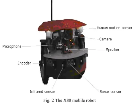
[image:2.595.63.291.586.726.2]The X80 mobile robot is used to implement and verify the current research. The main components of the robot which are used in the research are: the sonar sensors (to measure the distance to obstacles), the infrared sensors (to avoid the static obstacles), the human sensors (to detect human motion), the Wireless module (to communicate between the PC and the robot), the encoders (to determine the robot’s position in the environment, for localization), the camera (to take over images for correcting the orientation of the mobile robot). The X80 mobile robot is illustrated in fig. 2:
Fig. 2 The X80 mobile robot
C. The autonomous movement of the mobile robot in the dynamic environment
The purpose of this paragraph was to realize the mobile robot autonomous movement in partially known environments, characterized by maintaining the desired trajectory when static or dynamic obstacles are interfering.
The conceived algorithm for the mobile robot’s movement is illustrated in fig. 3.
The robot is equipped with two motors (one at each wheel), and one pulse encoder is placed at each wheel. These elements together with a software application, developed in Visual C++ programming language and intended to determine the mobile robot’s position (localization), are realizing the robot movement from an initial point to a final point in the environment.
If there are obstacles on the mobile robot’s trajectory, two situations are distinguished:
- a dynamic obstacle is detected – the robot stops and waits for the obstacle to disappear (to resume its moving) from its area;
- a static obstacle is detected – the robot will avoid the obstacle following the most convenient path regarding its position towards the obstacle.
robot’s orientation, to move along the obstacle with a constant speed and to memorize and calculate angles and coordinates.
Fig. 3 Logical scheme for the mobile robot movement
After the static obstacle is avoided, the robot will determine its current position and orientation, and it will start the movement towards the destination.
Fig. 4 The avoidance of a static obstacle
In order to operate successfully, the robot must know permanently its correct position and orientation. A fault affecting the localization module may lead to deviations from the desired trajectory. Such a fault can most commonly come from an odometry error. On very short distances the magnitude of the fault can be small, but on longer distances
the odometry errors may lead to large deviances from the desired trajectory and therefore to major faults.
D. The odometry errors
The odometry errors may lead to major faults and they are a serious factor in the mobile robot’s availability estimation. Many times, the robot is not able to realize its task because the odometry errors are causing deviations from the proposed trajectory and the robot will be lost in the environment.
There are two types of odometry errors: systematic and nonsystematic errors. Both are affecting the orientation of the mobile robot and therefore they are modifying its trajectory.
The sources of the systematic errors are: the unequal wheel diameters, the average of both wheel diameters differs from nominal diameter, the misalignment of the wheels, the uncertainties about the effective wheelbase, the limited resolution of the encoders, the limited encoder sampling rate.
The sources of the nonsystematic errors are: the movement over uneven floors, the movement over unexpected object on the floor, the slippage of the wheels due to: slippery floors, over-acceleration, fast tuning (skidding), action of external forces (interactions), action of internal forces (the castor wheel), non-point wheel contact with the floor.
Most researches are focusing only on the systematic odometry errors, realizing practically an a priori calibration [2], [11]. There are few studies that are treating the occurrence of nonsystematic odometry errors, an example being showed in [5], where the robot is not moving in dynamic environments.
III. METHOD TO CORRECT THE ORIENTATION OF
THE MOBILE ROBOT THROUGH IMAGE PROCESSING
The research from this paragraph is focused on orientation error correction realized online during the mobile robot’s movement. The correction method uses the redundant information taken over from various objects of the environment. In the current situation the redundant information is provided by the destination object (the target point). The redundant information is transmitted through image, and the image processing function provides the correction factor.
The image processing principle is based on:
i) extracting the pixels from the source image (the source image is representing the object to be identified) and grouping them in to colour families (the colour families are containing the related pixels – situated inside an admissible limit of red, blue and green regarding each other),
ii) eliminating all the pixels from the destination image (the image taken over by the camera in which the source image is searched) which are not belonging to any colour family identified in the source image, iii)eliminating the supplementary objects from the
[image:3.595.63.288.454.656.2]The elimination criterion is based on the number of the colour families found in each object of the destination image and also on the number of the pixels of each colour family.
The placement of the visual reference points (to provide the redundant information for the orientation correction) in the environment must be realized in order to obtain the optimal distances between each other because of two reasons:
- if the distance between the reference points is too small then the number of the image processing and correction subroutines is increased too much,
- if the distance between the reference points is too large then the odometry errors are determining an amplified orientation error and that is leading to large distance errors. The reference point may be outside the image frame and obviously the situation leads to time losses interrupting the continuous movement. In this case the current coordinates are erroneous and the mobile robot is lost.
The X80 wheeled mobile robot is equipped with a camera (see fig. 2). The camera captures the destination image and saves it in .bmp file format. The purpose of this procedure is to identify the searched object (OB1) in the destination image (IM2).
A. Extracting the searched object’s characteristics The pixels of OB1 are extracted from the source image (IM1) (fig. 5) and memorized in a two-dimensional matrix (MAT1). Each element of MAT1 provides three values corresponding to each pixel: red, green and blue. The dimension of the searched image corresponds to the
[image:4.595.374.495.137.225.2]dimension of the object in the destination image (taken over by the camera) in a correct functioning situation. In the next step the pixels of OB1 are extracted and grouped in colour families. Finally, the number of colour families, respectively the number of pixels contained by each colour family is memorized (for example, in fig. 5 the number of the colour families will be four).
Fig. 5 The searched object in the source image
C. Identifying the searched object in the destination image taken over by the camera
After taking over the IM2 image by the camera, the OB1 must be identified. The pixels of the IM2 are memorized in a second matrix MAT2. The image processing will eliminate first the pixels which are not belonging to the colour families of OB1. Then, step by step, the remained objects from IM2 are compared with each other and one by one they are eliminated until the searched object remains. At each step, two objects from IM2 are compared analyzing the number of colour families (the first criterion of elimination). If a decision cannot be made, then the number of pixels included in each colour family is compared between the objects (the second criterion of elimination).
Fig. 6 The destination image (IM2) Fig. 7 The image after the first processing Fig. 8 The searched object is identified
Fig. 6 illustrates the IM2 taken over by the camera. Fig. 7 is presenting the two objects remained after eliminations and in Fig. 8 OB1 is identified (after analyzing the number of colour families).
B. Determining the searched object position in the image and providing the information for correction
After identifying the searched object in the destination image, its current position has to be calculated (regarding the coordinates of the object in the image). The image processing module provides the deviation (∆x) regarding the correct expected position of the robot related to the searched object. The (∆x) deviation is transformed into an angle, respectively a number of impulses to correct the robot’s
orientation (fig. 9). Fig. 9 The orientation is modified regarding the current and the newly
[image:4.595.301.519.419.704.2] [image:4.595.341.520.533.697.2]IV. PRACTICAL STUDY
The purpose of this paragraph is to illustrate the efficiency of the correction method by presenting a practical study where the mobile robot will tolerate the odometry errors. The mobile robot (the X80 robot previously presented) will move from an initial point to a final point in a partially known environment.
At the beginning, the robot calculates the distance which is going to be covered and the angle made by the current orientation and the final point’s coordinates. After knowing this angle, the robot changes its orientation to be able to travel using the minimal route.
In the experimental scenario, during the movement, the mobile robot will meet a static obstacle which must be avoided. The procedure consists in three steps: to modify the robot’s orientation when the static obstacle is detected in order to avoid it, to calculate the current position and orientation after the obstacle disappears, respectively to modify the orientation and to start the movement towards the final destination.
If during the movement odometry errors are occurring, they are corrected using the image processing module (the reference object will be placed at the final point). At the
moment tx the image of the reference object is taken over by the camera. The reference object is easy to be identified due to the special configuration of colours (red, yellow and blue). To amplify the odometry errors and to be able to illustrate a larger correction of the orientation (the distance in the scenario was short), the reference object was pushed away from its normal position.
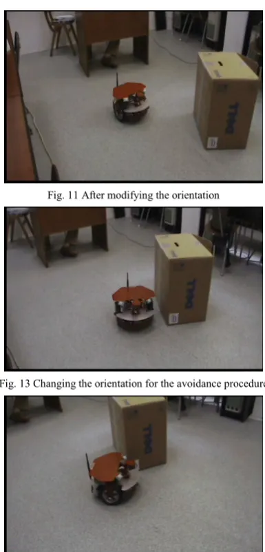
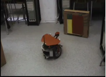
[image:5.595.328.521.318.720.2]The following figures are describing the evolution of the robot during the experimental scenario: the beginning of the movement (fig. 10 – the initial position, fig. 11 – after modifying the orientation to obtain the desired trajectory), the static obstacle avoidance (fig. 12 – the robot observes the static obstacle, fig. 13 – the modification of the orientation to avoid the obstacle, fig. 14 – the robot detects the static obstacle disappearance, fig. 15 – reorientation to evolve on the optimal trajectory towards the final point), the online correction of the odometry errors using the redundant information provided by the reference object through images (fig. 16 – the image from the reference object is taken over by the camera, fig. 17 – the orientation is corrected after the image processing), the travel to the destination (fig. 18 – the movement towards the destination, fig. 19 – the mobile robot reaches the destination).
Fig. 10 The robot in the initial position Fig. 11 After modifying the orientation
Fig. 12 Detecting the static obstacle Fig. 13 Changing the orientation for the avoidance procedure
[image:5.595.85.270.329.722.2]Fig. 16 The robot processes the image taken by the camera Fig. 17 The orientation correction after the image processing
Fig. 18 The movement towards the destination Fig. 19 Reaching the target
V. CONCLUSIONS
The paper presented a solution to avoid localization failures during the movement of a mobile robot by tolerating odometry errors using an online correction method based on image processing. As it is shown by the result of the availability study from the beginning, the online correction method is able to increase significantly the overall availability.
REFERENCES
[1] Austin, D., Kouzoubov, K., Robust, Long Term Navigation of a
Mobile Robot, Proc. IARP/IEE-RAS Joint Workshop on Technical
Challenges for Dependable Robots in Human Environments, October, 2002.
[2] Borenstein, J., Feng, L., UMBmark: A Benchmark Test for Measuring Odometry Errors in Mobile Robots, Proceedings of the SPIE Conference on Mobile Robots, Philadelphia, October 22-26, 1995
[3] Carlson, J., Murphy, R. R., Reliability Analysis of Mobile Robots, Proceedings of the IEEE International Concerence on Robotics and Automation (ICRA 2003), pp. 274-281, 2003
[4] Carlson, J., Murphy, R. R., How UGVs Psysically Fail in the Field, IEEE Trans. on Robotics, Vol. 21, No. 3, pp. 423-437, June, 2005 [5] Chong, K.S., Kleeman, L., Accurate Odometry and Error Modelling
for a Mobile Robot, MECSE-1996-6, 1996
[6] Fairfield, N., Kantor, G., Wettergreen, D., Real-Time SLAM with
Octree Evidence Grids for Exploration in Underwater Tunnels,
Journal of Field Robotics, 2007
[7] Korodi, A., Availability Analysis for Wheeled Mobile Robots, Proceedings of the International Conference ICM’08, Cd. Juarez, Mexico, October 16-17, 2008 (will be published)
[8] Long, M., Murphy, R., Parker, L., Distributed Multi-Agent Diagnosis
and Recovery from Sensor Failures, Proceedings of the IEEE/RSJ
International Conference on Intelligent Robots and Systems(IROS), Vol. 3, pp. 2506-2513, October 2003.
[9] Nourbakhsh, I. R., The mobot museum robot, Proceedings of the IEEE/RSJ International Conference on Inteligent Robots and Systems IROS 2002, Workshop Robots in Exhibitions, pp. 14–19, Lausanne, Switzerland, 2002
[10] Nourbakhsh, I. R., Kunz, C., Willeke, T., The Mobot Museum Robot
Installations: A Five Year Experiment, Proceedings of the IEEE/RSJ
International Conference on Inteligent Robots and Systems IROS 2003, Las-Vegas, USA, 2003
[11] Stachera, K., Schumacher, W., Herbst, O., Automatic Identification of Odometry Parameters of a Two-Wheel Mobile Robot Using Ultrasonic Sensors, Proceedings of the 12th IEEE International
Conference on Methods and Models in Automation and Robotics, 28-31 August, 2006, Miedzyzdroje, Poland
[12] Tomatis, N. et al., Design and system integration for the expo.02
robot, Proc. IEEE/RSJ IROS 2002 Workshop Robots in Exhibitions,
[image:6.595.85.272.60.199.2] [image:6.595.333.518.208.376.2] [image:6.595.87.269.226.359.2]