ISSN: 1816-949X
© Medwell Journals, 2019
Performance of Multylayers Smart Earthing System
1
Nofal M. Hussein and
2Shaymaa H. Nofal
1College of Engineering,
2
Department of Biomedeica Engineering, College of Engineering,
Warith Al-Anbia University, Kerbala, Iraq
Abstract: Vertical ground multylayers copper cylindrical earthing design have been used extensively for earth termination of electrical and lightning protection system. The experimental work shows that the efficiency of the design earthing system is much higher than the sound earthing cylinder which is more costing than that the multylayers design. Also, the other parameters such as current density, resistance and surface area, effected and shows relatively high result in cause of multylayers earthing system.
Key words: Earthing system, earth electrode, soilresistivity, TEP, earthing, costing
INTRODUCTION
Grounding or earthing described as electrical system connections to the earth mass. This system consists of electrical part and metal works associated with equipment, apparatus and appliance. The function of grounding to provide a path for the fault currents to the soil while maintaining the step and touch voltages at acceptable values, for limiting potential with respect to the earth mass to ensure safety. Earthing system designed with “zero impedance” to provide effective discharge of fault currents and prevent the potential rise at and around the substation. To get adequate grounding system performance, the system should be designed with low earth impedance and to get the optimum design of earthing systems can be achieved two parameters-earth electrode geometry and soil properties. In general resistivity soil range from a few Ω-meters for clay soil to several kilo-Ω-meters for rocks (ANSI/IEEE Std., 1983; Nor et al., 2000, 2006). Describing the change in resistivity for different soil type, grain size, temperature, moisture and salt content are important. Experimental work using wet clay mixed with sand under controlling amount at NaCl to get a range of low resistivity materials were performed (Nor et al., 2006) . The result shows that under impulse conditions, the apparent resistivity of wet clay decreased with increasing current ranges, suggest nonlinear soil-ionization. Generally, power systems are protected from lightning strokes by surge arresters provided with a low earth resist connection to keep large currents encountered to be effectively discharged to the general mass of earth which resist the flow of current. Earth resistance depends on arrangements and design of electrode, surrounding type of soil and there resistance. Combinations of different materials are used for ground resistance reduction, the results show considerable
reduction in the grounding resistance can be achieved when using such materials which in turn guided to improve performance of grounding (Al-Ammar et al., 2010). Ground rods vertically have been used for earth termination of electrical and lightning protection systems. The result of a comparison between three models for frequency dependent simulation of a ground rod: Lumped R-L-C circuit, the distributed-parameter circuit and the EM Model show significant differences at high frequencies. In the lumped circuit R-L-C Model is limited to cases where the length of the rod is >1-10 th of the wavelength in Earth, this limits the frequency range of the validity of this model to some lower frequencies, depending on the EM properties of the soil and of the rod. At higher frequencies, the model greatly overestimates the impedance to ground (Grcev and Popov, 2005).
Field tests of variable frequency (DC to 10 MHz) on different earth rod length reveal the benefits of extending rod length on low frequency performance, although these gains are less significant with longer rods. The steady indicate that higher frequencies, rod length extension may counterproductive with higher values of impedance record for the longer rods. The result shows relatively high agreement between experimental and simulation result is obtained (Mousa et al., 2012). A significant parameters of a 3-Gw 200-Kv DC superconducting cable system which influence the transient voltage distribution in the various park of the system cable was investigate it was found that the severity of the transient voltages are effected with the dielectric constant and the electrical resistivity of the soil (Pallem et al., 2006).
Investigation of the frequency depended behavior of the typical grounding systems for wind turbine was analysed. The system buried in a two dage soil. The relation between the various resistivity values and the alterations of the thickness of two soil layers was
examined. It was found that the touch voltage is depended upon the parameters of soil structure, shape and dimensions of the grids (Kontargyri et al., 2005). The objective: The aim of this study is to design a multilayers cylindrical copper earthing electrode with soil stated between the layers to increase the present rates of the lightening effects.
MATERIALS AND METHODS
Experimental work: Two parameters affecting the electrical properties of earthing system, they are the earthing resistance and configuration of the earth electrode. The earthing resistance is relationship between earth voltage and the earth current value. The earth electrode configuration means the potential distribution on the earth surface due to the result of current flow in the earth. To achieve low values of earth resistance, the current density of metal electrode flow to earth should be low in this cause the earth volume surrounding the electrode should be as lower as possible.
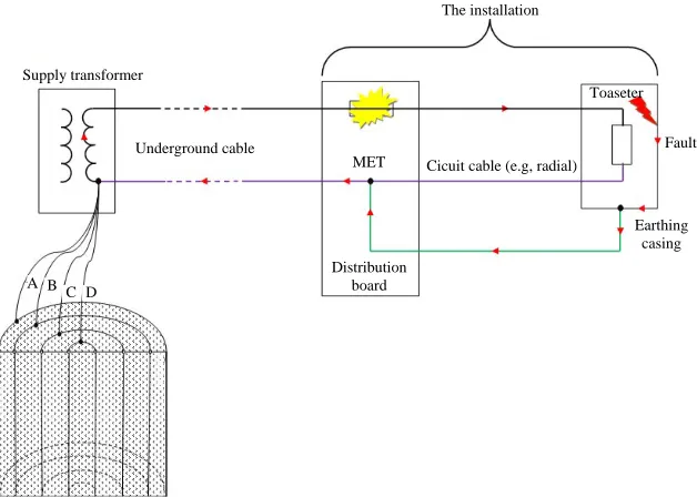
Copper sheet of 2 mm thickness used to manufacturing four cylindrical pipes shapes with the same length of 100 cm and different diameters of 6, 8, 10 and 12 cm, each of them connected with copper wire of 2.5 mm diameter all the wire brought together to be one wire of 10 mm diameter as shown in Fig. 1.
It can be seen from Fig. 1 that the variation is much more significant for the earthing multylayers system due that to two side of contact effect with soil as compare with sound cylindrical earthing electrode.
Impulse measurements: The number of earthing electrode and earthing resistance depends on the resistance of soil and time for fault current to posse through. Low voltage was carried out on the same earthing cylinders configuration which shown in Fig. 1. The Transient Earthing Potential (TEPR) rise for different surface area of earthing cylinder for a fixed current transmitted. From the figure, it can be seen that, for a fixed current transmitted, the voltage and current peaks occur at the same time for all cylinders indicating a predominantly a resistive response. In all cylinders the peak voltage decreases as the cylinder surface area increases.
Calculations Current density:
-2 I 7.57×1000/ ×t Am
Resistivity of soil 500 (Ω m) silty sand, poorly graded sand-silt mixtures ρ t = time dissipated (Table 1).
C Surface area of pipe:
C A = 2 π r L
C π = 3.14
C r = d/2 d = diameter of electrode
[image:2.612.134.448.475.699.2]C L = Length of electrode (100 cm) current dissipated (Table 2)
Fig. 1: Schmatic diagram of the earthing system
Supply transformer
Underground cable
MET
Distribution board
Cicuit cable (e.g, radial) Toaseter
Fault
Earthing casing The installation
400 350 300 250 200 150 100 50 0 Cu rr e n t d e n si ty (A m ) -2
0 0.5 1.0 1.5 2.0 2.5 3.0 3.5 4.0
Time (sec) 400 350 300 250 200 150 100 50 0 C u rr en t d e n sity (A m ) -2
0.3 0.4 0.5 0.6 0.7 0.8
Area (m )2
300 250 200 150 100 50 0 C ur re nt di ss ip at e (A )
0.5 1.0 1.5 2.0 2.5 3.0 3.5 4.0 Time (sec)
0.337 m2
0.502 m2
0.628 m2
0.754 m2 Table 1: Current density
t = time dissipated (sec) Current density (AmG2 )
1 338.54
2 239.38
3 195.46
4 169.27
Table 2:Surface area of pipe
Reduce (m) Current density (A mG2) Surface area (m2)
0.03 338.54 0.3768
0.04 239.38 0.5024
0.05 195.46 0.6280
0.06 169.27 0.7536
Table 3: Current dissipated
Current density (A mG2) Surface area (m2) Current dissipated (A)
338.54 0.3768 127.61
338.54 0.5024 169.93
338.54 0.6280 212.58
338.54 0.7536 255.23
239.38 0.3768 90.25
239.38 0.5024 120.18
239.38 0.6280 150.34
239.38 0.7536 180.51
195.46 0.3768 73.71
195.46 0.5024 98.14
195.46 0.6280 122.77
195.46 0.7536 147.41
169.27 0.3768 63.83
169.27 0.5024 84.99
169.27 0.6280 106.32
169.27 0.7536 127.65
Table 4: Current resistance
Diameter Resistance Resistance Resistance Resistance (m) (Ω)1 (Ω)2 ( Ω)3 ( Ω) 4 0.06 168.9227 168.6604 168.3961 168.1298 0.08 158.8882 158.5371 158.1825 157.8241 0.1 151.085 150.6445 150.1983 149.7463 0.12 144.6931 144.1625 143.6236 143.0762
Current dissipated:
C Id = I×A
C A = Surface area
C I = Current density (Table 3) R = ρ/2*3.14*L (loge (8*L/d)-1):
C = Resistivity of soil
C d = diameter of electrode
C L = Length of electrode (100 cm) (Table 4) RESULTS AND DISCUSSION
Figure 2 shows the relation between current density and lighting time. The current density decreasesas lighting time increases for multylayers earthing system, this induct that the distribution of current through the soil is effected by the increasing of contact air between soil and earthing system.
Figure 3 shows that the current density is effected by the increasing the soil earthing surface area of the each layer, so as the area of each soil layer increased the current can be dissipated vastly and required less time.
Fig. 2: Current density change with lighting time
Fig. 3: Current density change with contact area between soil and copper contacted areas
Fig. 4: Current dissipated change with lighting time for different surface area of copper
Figure 4 shows the relationship between current density and lighting time for different areas, so that, the general behavior is uniform but there is a significant effect of the area of each copper layer of the earthing system on the lighting time period.
Figure 5 shows the relationship between the surface area of the layer and the rate of current dissipated relative to the lighting time where the greater the surface area the higher the dissipated of current is greater and this indicates that the contact area between the surface layer of copper and soil is larger.
300
250
200
150
100
50
0
C
ur
re
n
t de
n
si
ty
(
A
)
0.3 0.4 0.5 0.6 0.7 0.8 Area (m )2
1 sec 2 sec 3 sec 4 sec
175
170
165
160
155
150
145
140
Re
si
ta
n
ce
(
)
Ω
0.05 0.07 0.09 0.11 0.13 Diameter (m)
170
165
160
155
150
145
140
Re
si
ta
n
ce
(
)
Ω
0.05 0.06 0.07 0.08 0.09 0.1 0.11 0.12 0.13
Diameter (m)
170
165
160
155
150
145
140
Re
si
ta
nc
e (
)
Ω
0.05 0.07 0.09 0.11 0.13 Diameter (m)
170
165
160
155
150
145
140
Re
si
ta
nc
e (
)
Ω
[image:4.612.328.528.99.209.2]0.05 0.07 0.09 0.11 0.13 Diameter (m)
Fig. 5: Current dissipated change with surface area of copper for different lighting time
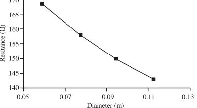
Fig. 6: Ground cylinder resistance versus diameter (for 1 m length)
Fig. 7: Ground cylinder resistance versus diameter (for 1 m length)
Fig. 8: Ground cylinder resistance versus diameter (for 1 m length) (3 sec lighting time)
[image:4.612.81.286.99.221.2]Fig. 9: Ground cylinder resistance versus diameter (for 1 m length) (4 sec lighting time)
Figure 6-9 show that the resistance of earth against the lighting current decreases while increasing the diameter of the cylindrical copper, this due to the increased in contact area between soil and copper surface, the shape of the relation is effected by the lighting period which means that the lighting current take short time to dissipated.
CONCLUSION
This study has focused on designing of multylayers smart earthing system. It is important to increase the earthing resistivity to reduce the time of dissipated the spark. From the laboratory testing, the following conclusions can be drowned. Increasing the contact areas between metal and earth reduce the sparking effects. The current density decrease is effected by increasing of earthing surface area of each layer.
Spark current dissipated rate effected by the earthing cylindrical area with time. Ground cylinder resistance effected inversely with surface area of cylinder at any sparking period time. Multylayers earthing system cost is more cheaper than the cost of sound cylinder. In multylayers earthing system we get twice contact surface areas in this cause the dissipated spark current is lower.
REFERENCES
NSI/IEEE Std., 1983. IEEE guide for measuring earth resistivity, ground impedance and earth surface p o t e n t i a l s o f a g r o u n d s y s t e m . http://ieeexplore.ieee.org/xpls/abs_all.jsp?tp=&isnu mber=1288&arnumber=30647&punumber=2464. Al-Ammar, E., Y. Khan, N. Malik and N. Wani, 2010.
Development of low resistivity material for grounding resistance reduction. Proceedings of the 2010 IEEE International Energy Conference, December 18-22, 2010, IEEE, Manama, Bahrain, pp: 700-703.
[image:4.612.91.289.269.389.2]Kontargyri, V.T., I.F. Gonos and I.A. Stathopulos, 2005. Frequency response of grounding system of wind turbine generators. Proceedings of the 14th International Symposium on High Voltage Engineering, August 25-29, 2005, Tsinghua University, Beijing, China, pp: 1-6.
Mousa, S., H. Griffiths, N. Harid and A. Haddad, 2012. Experimental investigation of high frequency and transient performance of earth rod systems. Proceedings of the 2012 International Conference on Lightning Protection (ICLP’12), September 2-7, 2012, IEEE, Vienna, Austria, pp: 1-5.
Nor, N.M., A. Haddad and H. Griffiths, 2006. Performance of earthing systems of low resistivity soils. IEEE. Trans. Power Delivery, 21: 2039-2047. Nor, N.M., S. Srisakot, H. Griffiths and A. Haddad, 2000. Characterisation of soil ionisation under fast impulse. Proceedings of the 25th International Conference on Lightning Protection, September 2000, Rhodes, Greece, pp: 18-22.