http://wrap.warwick.ac.uk
Original citation:Al Sebae, Alaa, Leeson, Mark S. and Green, Roger. (2014) On modelling network coded ARQ-based channels. International Journal of Space-Based and Situated Computing, 4 (2). pp. 65-76.
Permanent WRAP url:
http://wrap.warwick.ac.uk/73772
Copyright and reuse:
The Warwick Research Archive Portal (WRAP) makes this work by researchers of the University of Warwick available open access under the following conditions. Copyright © and all moral rights to the version of the paper presented here belong to the individual author(s) and/or other copyright owners. To the extent reasonable and practicable the material made available in WRAP has been checked for eligibility before being made available.
Copies of full items can be used for personal research or study, educational, or not-for profit purposes without prior permission or charge. Provided that the authors, title and full bibliographic details are credited, a hyperlink and/or URL is given for the original metadata page and the content is not changed in any way.
Publisher’s statement:
© Inderscience 2015
http://dx.doi.org/10.1504/IJSSC.2014.062467
A note on versions:
1
On modelling network coded ARQ-based channels1
Abstract-Network coding (NC) has been an attractive research topic in recent years as a means of offering a throughput improvement, especially in multicast scenarios. The throughput gain is achieved by introducing an algebraic method for combining multiple input streams of packets which are addressing one output port at an intermediate node. We present a practical implementation of network coding in conjunction with error control schemes, namely the Stop-and-Wait (SW) and Selective Repeat (SR) protocols. We propose a modified NC scheme and apply it at an intermediate SW ARQ-based link to reduce ARQ control signals at each transmission. We further extend this work to investigate the usefulness of NC in the Butterfly multicast network which adopts the SR ARQ protocol as an error control scheme. We validate our throughput analysis using a relatively recent discrete-event simulator, SimEvents®. The results show that the proposed scheme offers a throughput advantage of at least 50% over traditional SW ARQ, and that this is particularly noticeable in the presence of high error rates. In the multicast network, however, simulation results show that when compared with the traditional scheme, NC-SR ARQ can achieve a throughput gain of between 2% and 96% in a low bandwidth channel and up to 19% in a high bandwidth channel with errors.
Keywords: network coding; butterfly network; communication system; routing; automatic repeat request (ARQ); stop-and-wait (SW); selective repeat (SR).
1. Introduction
In today’s communication networks, data information is conveyed from a source to its intended receivers by routing. The network coding (NC) technique (Ahlswede et al. 2000), generalizes the traditional routing by allowing certain nodes to perform coding at their incoming data links. (Li et al. 2003) proved that the maximum achievable multicast rate can be achieved using a linear code. For a given multicast connection problem, (Koetter and Medard 2003) introduced a description for an algebraic linear coding solution.
Determining the encoding functions can be approached from two distinct situations. If the network is deterministic, each node will use predetermined local encoding coefficients. (Jaggi et al. 2005, Jaggi et al. 2003) investigated a deterministic network coding scheme for noisy
1'This article is a revised and expanded version of a paper entitled “The Throughput Benefits of Network Coding for SW
ARQ Communication” presented at the 27th International Conference onAdvanced Information Networking and
2
channels. On the other hand, random NC is used to generate encoding coefficients depending on a decentralized algorithm (Ho et al. 2003, Ho et al. 2004). However, random NC requires an overhead since the coefficients used in encoding have to be attached and transmitted with the resulting coded blocks (Chou et al. 2003).
In data communication systems, Automatic Repeat reQuest (ARQ) schemes are adopted to guarantee the reliable delivery of the transmitted packets in the presence of errors (Costello et al. 1998). ARQ schemes allow erroneous data to be retransmitted according to three major ARQ schemes: Stop-and-wait, Go-back-N and Selective Repeat (Kurose and Ross 2002). The Stop-and-Wait data transfer protocol is the simplest type of ARQ scheme. A receiver performs error detection on the packets received from the transmitter using error detection mechanisms such as Cyclic Redundancy Check (CRC) code. If no error occurs, the receiver replies with an acknowledgment (ACK) signal through a feedback channel. A transmitter must stop and wait for the acknowledgment of the transmitted packet. Upon the ACK arrival, the transmitter proceeds to send the next packet. However, if an error is detected in the received packet, the receiver sends a negative acknowledgment signal (NAK) asking for the same packet to be retransmitted. Therefore, the transmitter must keep a copy of the transmitted packet until an ACK is received. The procedure may be repeated as many times as necessary until an error free message is received.
Among all ARQ types, Selective Repeat ARQ is considered the most efficient whereby the transmitter is allowed to send a certain number of packets continuously without waiting for their acknowledgments. In addition, only corrupted packets are selectively retransmitted upon receiving negative acknowledgment from the receiver. Nevertheless, SR ARQ requires a sequencing algorithm to re-sort out-of-order correctly received packets.
At an intermediate link, we apply a modified NC scheme to produce a set of correlated packets rather than combined ones which is carried on using an encoding matrix rather than an encoding vector. In this way, the receiver has to send one ACK/NAK signal for all the correlated packets instead of acknowledging them individually. We then move back to the original concept of NC and investigate it effect on a multicast butterfly network.
3
Simulink® in MATLAB.
When employed in communication applications with a long roundtrip, ARQ is integrated with error correction to overcome the retransmission delay to produce a scheme known as Hybrid ARQ (HARQ) (Wozencraft and Horstein 1960). Previous work has been mainly focussed on the advantages of NC over HARQ, especially in the field of wireless communication (Yue et al. 2009, Dong et al. 2009, Eduardo et al. 2009). NC has a significant impact in wireless communication in a low bandwidth environment such as underwater networks (Guo et al. 2009, Lucani et al. 2008) which we will revisit during our analysis. This paper is split into two parts. In the first part, we study the overall throughput performance of a SW scheme in typical and NC scenarios experiencing different Packet Error Rates (PERs) using both simulation and numerical approaches. In the second part, the advantage of NC over a SR ARQ scheme is investigated over the multicast butterfly network.
2. Stop-and-Wait network coding scheme
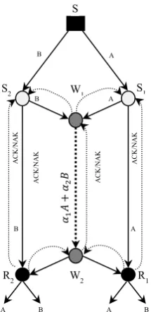
We apply our new NC scheme on the intermediate link (W1, W2) shown in Figure 1. The
Butterfly network modelled can be described by a finite directed graph G(V, E) where V is the set of nodes and E is the set of edges.
It is assumed that all edges have the same capacity C and noise can be applied on each edge separately. Two n-dimensional source packets are generated by source 𝑆 ∈ 𝑉 and transmitted through the network to each node {R1, R2}∈ 𝑉, referred to as the sink nodes. The
intermediate node, W1, has the option to encode blocks from the incoming links (S1, W1) and
(S2, W1). Sinks R1 and R2 are capable of decoding according to the same method applied in
[image:4.595.74.182.569.791.2]W1.
Figure 1The multicast scenario studied model A CK /N A K A B B A A CK /N A K A CK /N A K A CK /N A K A B 𝛼 1 𝐴 + 𝛼2 𝐵 R1
R2 W2
S1
S2 W1
S
A B
4
We employ a modified network coding scheme, NC-SW ARQ, to help in reducing the number of ACKs in the SW ARQ scheme at each transmission. Therefore, the achievable throughput can be significantly improved by reducing the propagation time needed for the ACK signals which consequently leads to a reduction in the idle time of the transmitter.
In practical random network coding (Chou et al. 2003), a file is divided into segments or generations, each data segment being further divided into k blocks with a predetermined size
n, as follows:
𝑑𝑎𝑡𝑎 𝑠𝑒𝑔𝑚𝑒𝑛𝑡 = [𝑏1, 𝑏2, … , 𝑏𝑘] (1)
The sender randomly chooses a vector of coding coefficients [𝑐1, 𝑐2, … , 𝑐𝑘] to produce a
linear combination 𝑥 of the original data block.
𝑥 = ∑𝑘 𝑐𝑖𝑏𝑖
𝑖=1 (2)
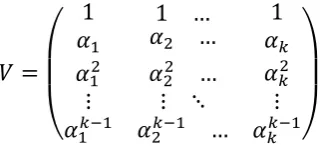
However, in our NC-SW ARQ scheme, packets at the transmitter are linearly encoded with random coefficients 𝐶𝑖𝑗 of an encoding matrix then advanced into the channel. By using an
encoding matrix, the output will advance a generation of k linearly correlated packets so that one ACK/NAK signal will be sufficient to acknowledge the reception of this generation. At the receiver side, a progressive decoding process (Shojania and Baochun 2007) using Gauss-Jordan elimination is used to extract back the original packets for each generation. Immediately after k linearly independent coded blocks which belong to the same generation, the receiver is able to recover the original packets in their entirety and sends an ACK to the sender. In this case, it is sufficient for the transmitter to receive back only one ACK/NAK signal for the total number of packets which consequently reduces the transmitter idle time from 2kTp to 2Tp time units, where Tp is the propagation time.
5
𝑉 =
(
1 1 … 1
𝛼1 𝛼2 … 𝛼𝑘
𝛼12
⋮ 𝛼1𝑘−1
𝛼22 …
⋮ ⋱
𝛼2𝑘−1 …
𝛼𝑘2
⋮ 𝛼𝑘𝑘−1)
(3)
The row elements of 𝑉 ensure a non-linear relationship between the encoded blocks which allows the receiver to decode once k blocks are received.
2.1.Simulation setup
The communication system employed is shown in Figure 2 consisting of packet generator, transmitter, receiver, forward channel, and feedback channel. Packets are generated at a rate of
λ per second, which is chosen according to the practical considerations discussed below. Blocks are not generated simultaneously. Therefore, the transmitter has to wait for k blocks to arrive and then advance them to the coding stage.
[image:6.595.204.365.72.146.2]Here, the throughput performance in a typical point-to-point communication system is investigated. The transmitter and receiver work over a 10 Mbps channel capacity. The forward channel is configured to vary according to a Bernoulli distribution model. Packets are transmitted over the transmission link, based on the SW ARQ scheme.
Figure 2 SW-ARQ based communication system
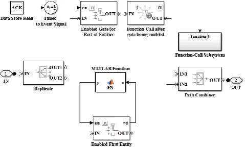
6 Figure 3 The transmitter general blocks
The acknowledgment signals generated at the receiver update the transmitter regarding the packet delivery status. This means that any packet being advanced to the transmission line or suspended is subject to the previously sent packet status. Due to the fact that there is no ACK/NAK for the first packet, it is necessary to construct a control unit to tackle this problem. The control unit subsystem shown in Figure 4 and consists of two paths. The lower path advances only the first packet to the transmission line so that it can generate an ACK/NAK signal at the receiver side, which in turn, can control the the rest of packets. The second path controls the rest of packets by reading the delivery status of the previously transmitted packet. This can be done by reserving a shared memory location using the data store memory block. This block is accessible by data store read/write block.
When a packet passes through the enabled gate, it calls a function that nullifies the store memory location using a write store memory block which stops any subsequent packet to go through. A succesflully transmitted packet writes a positive value in the memory location indicating that a new packet is allowed to pass. However, in case of unsuccesful trasmssion, the value of the memory loaction is kept zero till a succesful trasmission of this packet occurs.
Control Unit Replicate Packets
Forward Queue NAK
Switch
ACK
Check ACK/NAK
Sink In
[image:7.595.89.329.590.737.2]Out Path Combiner
7
2.2. Throughput analysis
The receiver is assumed to send back ACKs at a reasonable power. Therefore, the feedback channel is considered noise-free so that the acknowledgment signals will always be submitted to the transmitter. The time required to transmit one bit from the source to destination is called the propagation time Tp. The transmission delay Tt is defined as the time consumed in
emitting all the bits comprising the block into the transmission channel. Given the Bit Error Rate (BER), the probability that the transmitted block of size n contains an error PER, is given by:
PER = 1 − (1 − BER)n (4)
For a noise-free channel the BER is zero PER = 0.
𝑇𝑐𝑜𝑑 is an additional time delay which has to be taken into account while NC is employed. This delay mainly represents the time to process 𝑘 × 𝜁 waiting blocks, where 𝜁 = 1/𝜆 is the intergeneration time. The coding operation itself, in today’s advanced routers, tends to take a relatively negligible amount of time.
The throughput 𝑇ℎ of a SW ARQ scheme is defined as 𝑇ℎ = 𝑇𝑡𝑟𝑎𝑛𝑠/𝑇𝑡𝑡, where, 𝑇𝑡𝑡 is the
overall time between two consecutive blocks. In typical SW ARQ, the propagation delay 𝑇𝑝
plays a significant role in 𝑇𝑡𝑡. That is, when sending k blocks of data, the total idle time that the transmitter has to wait is 2𝑘𝑇𝑝 while in NC-SW ARQ the idle time is reduced to 2Tp which saves 2(𝑘 − 1) 𝑇𝑝.
2.3. Performance results
In this section, simulation results are provided in order to characterize the throughput performance. In the case of SW ARQ only, the maximum throughput achievable is when the system is operated over error-free channels and the intergeneration time is slightly greater than the round-trip delay RTT.
The time 𝑇𝑡𝑡 , in SW ARQ, is given by:
𝑇𝑡𝑡 = 2𝑇𝑝+ 𝑇𝑡 (5)
whereas in NC-SW ARQ, 𝑅𝑇𝑇 and 𝑇𝑐𝑜𝑑 become part of the total transmission time 𝑅𝑡𝑜𝑡
𝑅𝑡𝑜𝑡 = 𝑅𝑇𝑇+ 𝑇𝑐𝑜𝑑 (6)
Equation (5) indicates that 𝑇𝑝 plays the key role in SW ARQ efficiency, while (6) states that
8
coding waiting delay can be reduced to the minimum once the intergeneration time is decreased, if possible.
2.3.1.System parameters
The propagation delay was chosen according to the distance between the East and West Coast of the United States, which is approximately 15 milliseconds considering the distance and the speed-of-light propagation. The system bit rate was 10 Mbps, so that the time needed to
actually transmit a 1000 bit packet (𝑇𝑡) was 100 s. The intergeneration time chosen was
𝜁 = 0.02 seconds according to (6) for both SW and NC-SW ARQ scenarios. The sender node
[image:9.595.76.312.343.495.2]is assumed to be located in a moderately sized network where the number of its incoming links is chosen to be five.
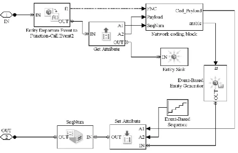
Figure 5 depicts part of the coding stage where the packets generate a function call to execute a NC program written in the MATLAB language
Figure 5 Network coding process model prior to transmission stage
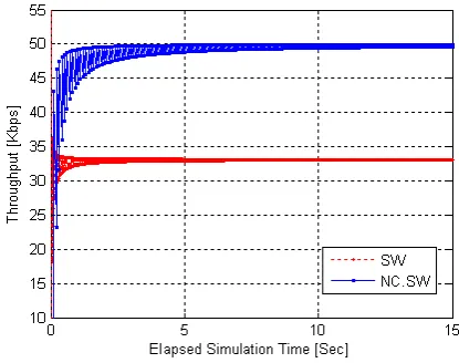
9 Figure 6 SW and NC-SW throughput over an error free channel
Figure 6 depicts the maximum achievable throughput for the SW and NC-SW ARQ systems under the same packet generation time against the elapsed simulation time. It may be observed that NC-SW ARQ achieves a throughput ~49.5 kbps, close to the highest possible throughput at the generation rate equal to 1/(0.02) = 50 kbps. This is because NC-SW saves 2(𝑘 − 1) 𝑇𝑝𝑟𝑜𝑝 in every k transmissions. The traditional SW ARQ methods delivered only ~33 kbps. This is because 2𝑇𝑝 is required for each packet transmission in SW ARQ. In
addition, NC-SW can accept a larger data rate which leads to a better channel utilization.
[image:10.595.96.305.490.652.2]Figure 7 and Figure 8 show that with growing PER, packet retransmission occurs, adding more delay which is equal to the same time required for sending the same number of correct packets.
10 Figure 8 SW and NC-SW throughput when PER is 0.1
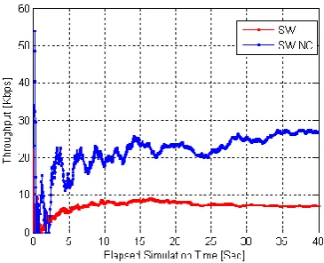
Figure 9 shows a drastic degradation in network throughput for SW when the PER is 0.6 (i.e. BER=10−3). NC-SW still provides a reasonable service with a throughput some three times
that of SW. It is noticed the throughput rate is fluctuating in the NC-SW scenario, and this is reasonable due to the retransmission of the entire corrupted generation in the case of an error.
[image:11.595.85.268.405.553.2]The average throughput for SW and NC-SW with PER is demonstrated by Figure 10, where a clear benefit to NC can be seen for all cases considered.
[image:11.595.84.262.588.736.2]Figure 9 SW and NC-SW throughput when FER is 0.6
11
2.3.2.Performance optimization
To achieve the maximum throughput possible, the packets generated should always be ready to be sent. In the case of SW ARQ, the packet intergeneration time, 𝜁, has to be equal or slightly smaller than the round-trip delay, i.e.
𝜁 ≤ 2𝑇𝑝+ 𝑇𝑡 (7)
Therefore, the optimum throughput in this case can be achieved when 𝜁 obeys (7). However, any decrease in 𝜁 will incur a queuing problem and will not affect the throughput value due to the propagation time domination constraint.
In the case of NC-SW 𝜁 can be calculated by making the total coding delay slightly smaller than the round-trip delay. This allows a faster data rate which can be easily achieved by modern technology, resulting in:
𝑘𝜁 + 𝑇𝑐𝑜𝑑 ≤ 2𝑇𝑝+ 𝑇𝑡 (8)
𝜁 ≤ (2𝑇𝑝+ 𝑇𝑡− 𝑇𝑐𝑜𝑑)/𝑘 (9)
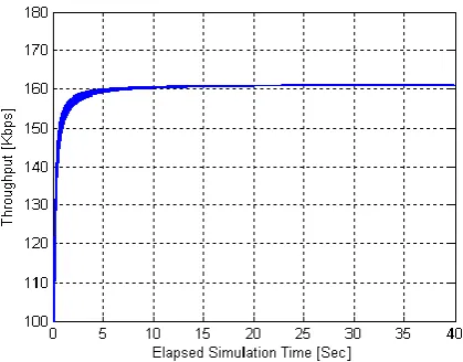
[image:12.595.95.305.501.665.2]Implementing equation (9) in the NC simulation yielded the result shown in Figure 11. In contrast to SW ARQ, it may be seen that the value of 𝜁 can greatly improve the throughput of NC-SW ARQ. This improvement comes from allowing new packets to always be ready to be coded rather than waiting for the packets to be generated.
Figure 11 The NC-SW ARQ maximum throughput when the optimum intergeneration time is applied
3. On network coding SR ARQ-based channel
12
encoded via an encoding vector and sent as one coded packet. Therefore, we can reduce the total delivery delay and save the required number of ACK/NAK signals compared to traditional SR ARQ. Inspired by this fact, we investigate the throughput performance of the
Butterfly multicast network based on SR ARQ in conjunction with a deterministic network coding scheme.
3.1. System model and Performance evaluation
In the simulated network shown in Figure 1, we implement network coding using (𝛼1 and 𝛼2)
as encoding coefficients, the link (W1, W2) can transmit coded blocks 𝛼1𝐴 + 𝛼2𝐵 of the same
size n to both R1 and R2 saving half of the transmission time needed at W1 at each
transmission. Thus, the sink R1, for instance, can extract the original packets by solving the
following equation:
𝑅1: (𝐴
𝐵) = (
1 0
𝛼1 𝛼2)
−1
{𝛼 𝐴
1𝐴 + 𝛼2𝐵} (10)
The coding nodes have to satisfy the inversion condition by ensuring a nonzero positive value
of the decoding determinant. Inspired by (Stallings 2004), we use the parameter: 𝑐 =𝑇𝑝+𝑇𝑡
𝑇𝑔𝑒𝑛 =
𝛼 + 𝑇𝑡
𝑇𝑔𝑒𝑛, where 𝑇𝑝 is the propagation time delay and 𝑇𝑡 is the transmission time required to
emit one bit from the transmitter or receiver, and 𝑇𝑔𝑒𝑛 is the time at which the packets are
generated. The data propagation to data generation time ratio 𝛼 = 𝑇𝑝
𝑇𝑔𝑒𝑛 is used as a factor for
clear comparison and simulation convenience.
When the data segment blocks are about to transmit, the source S chooses a set of coding coefficients [𝐶1,𝑘] to produce a linear combinations X of the original data blocks.
𝑋𝑗 = ∑𝑘 𝑏𝑖𝑐1𝑖
𝑖=1 (11)
In a traditional SR ARQ scheme, the receiver acknowledges correctly received packets and sends ACK signals for each packet. Nevertheless, in NC-SR ARQ, the receiver at the intermediate link acknowledges coded blocks of size n that represent a collection of K
13
this can significantly improve the throughput efficiency of the system, especially in a noisy environment.
If the NC-SR ARQ scheme is adopted, the probability that a coded block of size n contains an error is given by:
𝑃𝐸𝑅 = 1 − (1 − 𝐵𝐸𝑅)𝑛 (12)
therefore
(1 − 𝐵𝐸𝑅)𝑛 = 1 − 𝑃𝐸𝑅 (13)
where BER is the Bit Error Rate
In a traditional SR ARQ scenario, the value of packet error rate varies to obey the following equation:
𝑃𝐸𝑅𝑡𝑟 = 1 − (1 − 𝐵𝐸𝑅)𝐾𝑛 (14)
From (13), 𝑃𝐸𝑅𝑡𝑟 can be rewritten as:
𝑃𝐸𝑅𝑡𝑟 = 1 − (1 − 𝑃𝐸𝑅)𝐾 (15)
where K represents the number of packets present at the input port of the intermediate node and destined to the same output port.
Two cases need to be considered to evaluate both scenarios’ performance:
Case 1: 𝑤 ≥ 2𝑐. The ACK/NAK signal of any transmitted packet will return to the receiver before exhausting the transmitter queue. In this case, the transmitter sends packets continuously without any pausing. Hence, the throughput will be at its maximum.
Case 2: 𝑤 < 2𝑐. The transmitter queue starts to exhaust accumulatively. Therefore, during the transmission, the transmitter cannot send additional packets until a space becomes available by receiving an ACK/NAK signal. Thus, the normalized throughput 𝑇ℎ can be expressed as follows:
𝑇ℎ = {1 𝑊 ≥ 2𝑐𝑊
2𝑐 𝑊 < 2𝑐
14
If errors occur, (16) is divided by the expected number of transmissions 𝑁𝑡 = 1/(1 − 𝑃𝐸𝑅)
of a packet before it is successfully received. Hence, 𝑇ℎ becomes
𝑇ℎ = {1 − 𝑃𝐸𝑅 𝑊 ≥ 2𝑐𝑊(1−𝑃𝐸𝑅)
2𝑐 𝑊 < 2𝑐
(17)
By substituting (15) into (17), the throughput obeys the following formula in traditional SR ARQ, 𝑇ℎ𝑡𝑟:
𝑇ℎ𝑡𝑟 = {
(1 − 𝑃𝐸𝑅)𝑘 𝑊 ≥ 2𝑐
𝑊(1−𝑃𝐸𝑅)𝑘
2𝑐 𝑊 < 2𝑐
(18)
Equation (18) indicates that the throughput performance starts to degrade when one of the network queues becomes full after a specific time determined by the parameter c.
In comparison with SR ARQ, an NC-SR ARQ achieves a higher throughput advantage especially with increasing K, as 𝑇ℎ𝑡𝑟 decreases exponentially.
In the traditional SR ARQ scenario, packets are advanced one after the other at the output port, resulting in a 𝐾𝑁𝑡 time delay. Therefore, the key factors that specify the link performance are the packet error rate, the bandwidth at which the node is operating, and the packet size that has to be handled at the intermediate node. In fact, the bandwidth and the
Packet Size (PS) can be investigated as one factor, since 𝑇𝑡= 𝐵𝑎𝑛𝑑𝑤𝑖𝑑𝑡ℎ𝑃𝑆 .
3.2. Model structure in SimEvents
The model designed is composed of a set of sending, receiving and intermediate nodes. All nodes are connected through a communication link that employs SR ARQ protocol as its error control scheme. Moreover, each link has a configurable propagation time delay and adjustable error pattern. The error pattern is set to vary according to a Bernoulli distribution. As shown in Figure 12, sender S advances a replica of packets to the input port of both senders S1 and S2 using the Replicate box. The nodes W1, R1 and R2 are equipped with two
receivers according to the number of their incoming links. One of the output ports of S1 is
directly connected to one of R1 receivers and the other is connected to one of W1 receivers.
15
Receivers R1 and R2 are provided with a Path Combiner box which allocates several
incoming streams into one stream. This allows both receivers to calculate the throughput value at the outgoing links. The major infrastructure difference between the traditional SR ARQ and NC-SR ARQ scenarios is the type of the intermediate node, W1. While a typical switch is used in the traditional SR ARQ, a Packet Combiner box is chosen to represent W1 in
the NC-SR ARQ. The switch routes the upcoming packets according to certain switching criteria. The Round Robin criterion is the choice for our model where, after each departure, the switch selects the entity input port next to the last selected port. The incoming packets from node S1 are labeled with an identification number (ID) which distinguishes them from
those packets coming from node S2. Using the ID number, node W2 will be capable of routing
the packets coming from (W1, W2) to their intended destinations, i.e. R1 and R2. On the other
hand, the Packet Combiner acts like a coding stage where it waits for all packets to be present at its incoming links to produce one combined packet. This packet is to be advanced through the intermediate link to W2 which in turn makes a copy of the coded packets using the Replicate box and advances them to both R1 and R2. If W2, in the SR ARQ scenario, is
considered a merely relaying station, receivers R1 and R2 receive extra copy of the packets A
and B respectively. Consequently, this will incur throughput wastage at the receivers. However, results show that this wastage becomes negligible when the system is operating at a high data rate where the transmission time delay has a very small value.
Nodes at their transmitting side are provided with a First in First out (FIFO) queue which controls the number of unacknowledged packets on the transmission line. Similarly, receivers maintain a queue of the same size to store out-of-order correctly received packet until
R2: Path Combiner
R1: Path Combiner
S: Generator
S2: Replicate
W1: Switch / Packet Combiner
S1: Replicate
W2: Replicate/
Switch
Figure 12 Simevents-based model
Tp/3 Tp/3 Tp/3
Tp/3
Tp/3
16
receiving any requested low-sequenced packet leading to a sequential submission of a batch of packets to the upper layer. Throughput is calculated as the ratio of the number of packets received per time unit.
We assume that the receivers are capable of decoding at the absence of synchronization. That is, coded packets are not required to wait for the arrival of its corresponding packet of the other flow. Instead, they will arrive at the receivers in pairs.
3.3. Simulation results
In this section, we present the results of simulations of three different multicast scenarios and reveal the best scenarios where network coding becomes most efficient. We vary the factor α
by changing the propagation delay due to the speed of light at each edge.
We first focus on the throughput performance in different bandwidths with a fixed data rate and seek to examine the usefulness of NC in these scenarios. In all scenarios, unless otherwise mentioned, entities are generated at the source node S as data packets at a rate of 10 per second with length of 1000 bits and the transmitter forward queue size is set to fit 100 packets.
3.3.1.Different communication bandwidths scenario
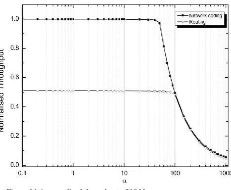
[image:17.595.77.315.478.659.2]In this scenario, the simulated model is analyzed based on error-free channels with 100 kbps bandwidth. Having 1000 bits for each packet, the transmission time required for a node to emit one packet onto the transmission line is equal to 0.01 sec.
17
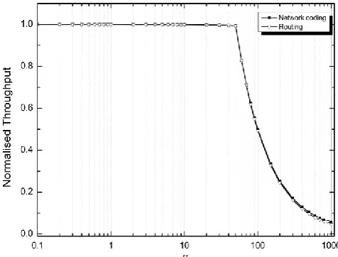
Figure 13 shows that at a relatively high value of a, NC achieves between 1.35% and 18% throughput gain over the traditional SR ARQ when employed in one communication link. This is because the packets do not have to wait at the intermediate nodes to be forwarded through the shared link. Figure 14, however, shows that the multicast network, in low bandwidth communication, suffers from underutilizing the available bandwidth which necessitates the need to adapt network coding in low bandwidth communication to gain the most of its characteristics. Numerically, NC achieves a throughput gain of between 2% and 96% when a varies from a high to low value. This gain starts to converge at a certain point where, for both scenarios, W1 queue becomes filled up and hence regulates the data rate
instead of the transmitter S. The aforementioned advantage of NC in low bandwidth environment has already triggered some research efforts in underwater sensor networks where the low bandwidth, long propagation delays and high error probability are the main characteristics of the channel (Guo et al. 2006, Guo et al. 2009).
Similar experiments conducted on 10 and 1 Mbps channels showed that NC provides little improvement in terms of the throughput gain.
3.3.2.Different error patterns scenario
Now, we consider the case where the network channels are not necessarily error-free. We apply errors with a probability of 0.1 and a bandwidth equal to 100 kbps. The comparison is carried out first by injecting errors at the non-coding link (S1, R1) and then at the coding link
(W1, W2).
Errors occur at the coding link (W1, W2):
[image:18.595.77.311.70.262.2]Routing case: original packets are unequally subject to errors. This leads to a very slight difference between R1 and R2 in throughput performance.
18
Network coding case: because only the coded blocks are transmitted over (W1, W2),
both R1 and R2 will have the same throughput value. Network coding offers between 2% to
14% throughput gain as the factor 𝛼 varies which shows the merit of mixing at the intermediate node.
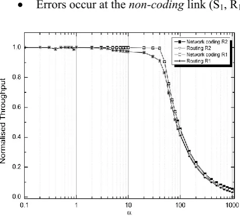
Errors occur at the non-coding link (S1, R1):
Routing case: R1 requests a retransmission for the corrupted packets. Henceforth, S1 will
retransmit the corrupted packets to R1 which delays sending a new packet through the link
(S1, W1) which affects R2 throughput as well.
[image:19.595.83.322.91.280.2]Network coding case: the network will act the same as in the Routing case. However, when the factor 𝛼 reaches the value of 90, NC provides a reasonable service with a throughput gain of between 1% and 23% for R1 and between 1% and 19% for R2.
Figure 15 Error at a coding link
[image:19.595.85.323.386.600.2]19
3.3.3.Different data rate source scenario
In this scenario, we set the source S to send packets at a different data rate. Data are sent over (S, S1) at a rate of 100 kbps and 50 kbps over (S, S2). Since the switch uses the Round Robin
criterion, the link (W1, W2) will be operating on the lower data rate i.e. 50 kbps. This means
two packets at every 0.2 sec since each packet has 1000 bits and packets are coming from two streams. Similarly, when NC is employed, node W1 has to wait the presence of packets from
both streams at its input ports to be able to perform coding. This leads to an operation of the lower data rate over (W1, W2) as well. Since, however, NC will eventually advance one
packet every 0.2 sec due to coding; the transmission time at the output port of W1 will be
reduced to its half. In this scenario, simulation results show that NC can have up to 4% throughput achievement over the SR ARQ in 100 kbps bandwidth channel.
4. Conclusion
In the presence of higher data rates and long round-trip delays, SW ARQ becomes inefficient due to the increased transmitter idle time. The proposed NC scheme offers an increase in the throughput of traditional SW ARQ that ranges at least from 50%, with negligible decoding delay. However, this improvement does not reach the k-multiple throughput of the normal node unless the characterized intergeneration time is applied. This is because of the approximate k depreciation of the data rate of the packets sent. We next evaluated the throughput performance of selective repeat ARQ in conjunction with NC. This is done over one coding node and under different bandwidth, error pattern and data rate scenarios. The performance results showed that bandwidth and packet length are driving concerns at the intermediate nodes. Under both erroneous and low bandwidth scenarios, NC has showed a noticeable impact on the SR ARQ throughput performance. It is evident that NC can be utilized to reduce the bottleneck which occurs at a shared server when a number of packets addressing the same destination compete to be processed. This impact becomes more evident once NC is employed over a properly designed network where several links have to apply NC. This forms the basis of our future work.
References
20
Alsebae, A., Leeson, M. and Green, R. (2013a) 'SimEvents-based Modeling and Simulation Study of Stop-and-Wait Protocol', The 5th International Conference on Modeling, Identification and Control.
Alsebae, A., Leeson, M. and Green, R. (2013b) 'The Throughput Benefits of Network Coding for SW-ARQ Communication', the 27th International Conference on Advanced Information Networking and Applications.
Bruen, A. A. and Forcinito, M. A. (2011) Cryptography, Information Theory, and Error-Correction: A Handbook for the 21st Century, John Wiley & Sons.
Chou, P., Y.Wu and K.Jain (2003) 'Practical network coding', in proc. of allerton conference on communication, Control and computing.
Costello, D. J., Jr., Hagenauer, J., Imai, H. and Wicker, S. B. (1998) 'Applications of error-control coding', Information Theory, IEEE Transactions on, 44(6), 2531-2560.
Dong, N., Tran, T., Thinh, N. and Bose, B. (2009) 'Wireless Broadcast Using Network Coding',
Vehicular Technology, IEEE Transactions on, 58(2), 914-925.
Eduardo, A., Mario E. Magana and Nguyen, T. (2009) 'Error propagation mitigation for wireless network coding', International Journal of Autonomous and Adaptive Communications Systems, 2(2).
Gray, M. A. (2007) 'Discrete Event Simulation: A Review of SimEvents', Computing in Science & Engineering, 9(6), 62-66.
Guo, Z., Wang, B., Xie, P., Zeng, W. and Cui, J.-H. (2009) 'Efficient error recovery with network coding in underwater sensor networks', Ad Hoc Networks, 7(4), 791-802.
Guo, Z., Xie, P., Cui, J.-H. and Wang, B. (2006) 'On applying network coding to underwater sensor networks', in Proceedings of the 1st ACM international workshop on Underwater networks, Los Angeles, CA, USA, 1161062: ACM, 109-112.
Ho, T., Koetter, R., Medard, M., Karger, D. R. and Effros, M. (2003) The benefits of coding over routing in a randomized setting, translated by 442.
Ho, T., Médard, M., Koetter, R., Karger, D. R., Effros, M., Shi, J. and Leong, B. (2004) 'Toward a random operation of networks', submitted to IEEE Trans. Inform. Theory.
21
Jaggi, S., Sanders, P., Chou, P. A., Effros, M., Egner, S., Jain, K. and Tolhuizen, L. M. G. M. (2005) 'Polynomial time algorithms for multicast network code construction', Information Theory, IEEE Transactions on, 51(6), 1973-1982.
Koetter, R. and Medard, M. (2003) 'An algebraic approach to network coding', Networking, IEEE/ACM Transactions on, 11(5), 782-795.
Kurose, J. F. and Ross, K. (2002) Computer Networking: A Top-Down Approach Featuring the Internet,
Addison-Wesley Longman Publishing Co., Inc.
Li, S. Y. R., Yeung, R. W. and Ning, C. (2003) 'Linear network coding', Information Theory, IEEE Transactions on, 49(2), 371-381.
Lucani, D. E., Medard, M. and Stojanovic, M. (2008) A lower bound to transmission power for multicast in underwater networks using network coding, translated by 1-6.
MathWorks (2005) 'SimEvents User's Guide.'.
Shojania, H. and Baochun, L. (2007) Parallelized Progressive Network Coding With Hardware Acceleration, translated by 47-55.
Stallings, W. (2004) Computer Networking With Internet Protocols and Technology, Pearson/Prentice Hall.
Wozencraft, J. M. and Horstein, M. (1960) 'digitalised communication over two-way channels',
presented at the fourth london symp. information theoty.
Yue, S., Ying, L. and Xinmei, W. (2009) Cooperative hybrid-ARQ protocol with network coding,