Genetic Controller Stator-Flux Orientated Vector Control
of Doubly-Fed Induction Generator for Wind Power
Generation System
Hanan M. Dawood Habbi
Electrical Engineering Department, College of Engineering,
University of Baghdad
ABSTRACT
In this paper, a genetic controller that is described in wind power generation system. In order to model the system that based on stator vector control oriented (VCO), a dynamic mathematic model of doubly-fed induction generator (DFIG) is utilized. The comprehensive designed system includes the modeling of DFIG with space vector PWM on the rotor side grid as well as the gird area. The genetic algorithm used active and reactive power to obtain the required reference currents components. The simulation results demonstrate that the system performs a speed response without over shoot. The obtained simulation results are simulated by Matlab/Simulink 2017a.
Keywords
Wind turbine, genetic speed controller, DFIG model.
1.
INTRODUCTION
The new developments in wind energy system which is a clean and renewable energy resources leads to develop turbines in order to generate an economical power in low wind speed areas [1].
There are a fast growth of using the renewable system in industrial application [2-4]. As a result of the decoupling between the frequency of the grid and the output power consequently a doubly-fed induction generator based wind power plant does not involve frequency response [5].
The technology of the wind power generation technology is emerging from stall speed power generation to variable speed power generation because of the advantages of maximum absorption of wind power and flexible connection between electric and machine [6].
In order to make the wind turbine work in best tip-speed-ratio therefore, the active power P is controlled by controlling the speed of the wind turbine system which accomplishes greatest wind power capture.
The conventional PI controllers have been proposed by many researchers for controlling the active and reactive decoupling control in doubly-fed generation. Hence, three PI controllers be influnced by their parameter gains. Once, the controller parameters are inaccuracy or charging due to any disturbance. To solve there problems and to optimize the performance, it required to select the suitable PI gains, even more this process which is varied during the dynamic operation that will become the system in nonlinear inhernatly.
To overcome these difficulties, artificial intelligent algorithms have been adopted to optimize and regulate the values such as Fuzzy and Fuzzy Neural networks which are not relied on mathematics mode are adopted [7]. But these algorithms are complex and need amounts of computation, which go against real-time control.
A dynamic mathematic model of wind turbine plant approves stator-flux vector control orientation is implemented. The genetic algorithm is utilized to control the speed response in order to improve its performance.
2.
WIND TURBINE MODELLING
The mechanical power (Pm) occupied from wind by a wind turbine can be obtained by:
2 3
1
( , )
2
m p
P
C
R v
(
1
)
Where,
: air density(Kg/m3)R
:radius of wind turbine v: wind speed (m/s)( , ) p
C
: power coefficient of the wind turbine As the air density, radius of wind turbine and wind speed are constant, the output of the turbine will be a function of power coefficient of the wind turbine. Furthermore, the wind turbine is normally characterized by itsCp( , )
curve.Equation 2 gives
mwhich is the turbine rotor speed in “rad/s”. where
is the tip-speed ratio.
mR
v
(2) A typical relation of power coefficient of the wind turbine with tip speed ratio is shown in Figure 1 for a wind turbine for a
constant pitch angle (
). It can be observed that the optimumefficiency can be obtained when the values of
opt Cp are maximum. Accordingly, it can achieved the maximum powermax
P
from wind turbine.2 3 max max
1
2
pP
C
R v
(3)Due to DF induction generator power relationships give:
1 s e sloss
m e
P P P P P s
(4)
Where,
P
s: stator active power;P
e: electromagnetic power;sloss
P
: stator copper consumption and iron losses;P
m: net mechanical power input for generator; s:slip angular speed.Turbine control can be controlled either by passive control or active control. The passive control techniques reduce loads without an external energy or auxiliary power. Active control techniques require an external energy therefore the turbine costs will be increased [5].
In order to achieve maximum wind energy, the active power *
s
P is calculated according to best power curve in real time.
* max 1 s sloss P P P s
(5)
3.
GENETIC CONTROLLER BASED
STATOR-FLUX VCO OF DF
INDUCTION GENERATOR
The energy for the converter flows in two directions when the stator of DFIG is connected to the power grid [3].
The vector control of stator flux orientation is implemented in order to get a better control performance. The d-axis component of synchronization coordinate reference is coincided with the
stator flux vector
s.The stator frequency and the power grid frequency are same when the DFIG is in the steady state operation, it can be observed that, the voltage drop on the stator resistance is less than the voltage drop on the reactance and the electromagnetic force of the generator. Therefore, the voltage of stator resistance can be ignored.
The phase of stator winding voltage vector is in advance of 90 degree compared with stator winding flux vector.
It can be resolved as,
0
sd s sq
(6)The dq voltages are,
sd
0
sq s s su
u
U
(7) Then,
0
sd s s sd m rd
sq s sq m rq
L i
L i
L i
L i
(8)The flux linkages at the d and q axes are:
2
( )
m m
rd s r rd
s s L L L i L L
(9) 2 ( m)rq r rd
s L L i L
(10)Then the voltage equations are obtained:
2 1 2 ( ) ( ) ( ) m rd
rd r rd r r
r
m
r rq
s
L di u R i L
L dt L L i L
(11)
2 1 2 1 ( ) ( ) ( ) ( ) rq m
rq r rq r r
r
m m
r rd r s
s s
di L u R i L
L dt L L L i L L
(12)
At steady state condition,
0 rd
di
dt ,
0
rq
di
dt
,get,
2 1
( )( m)
rd r rd r r rq
s
L
u R i L i
L
(13)
2
1 1
( )( m) ( ) m
rq r rq r r rd r s
s s
L L
u R i L i
L L
(14)
4.
DYNAMIC MODEL OF DFIG
The dynamic model is based on the stator and rotor voltage of DFIG in synchronous rotating coordinate reference (d, q) [8] and [9]:
1 1
sd s sd sd sq
sq s sq sq sd
u
R i
p
u
R i
p
(15)1 1
(
)
(
)
rd r rd rd r rq
sq r rq rq r rd
u
R i
p
u
R i
p
(16)The stator and rotor flux of the DFIG equations are denoted by:
sd s sd m rd
sq s sq m rq
L i
L i
L i
L i
(17)rd m sd r rd
sq m sq r rq
L i
L i
L i
L i
(18) where,Where,
p
is differential operator;R
s andR
r are statorresistance and rotor resistance respectively;
L
s,L
r andL
mare stator equivalent inductance and rotor equivalent inductance and mutual inductance in d q coordinate reference;u
sd and usqrd
u
and urq are d axis component and q axis component ofrotor voltage;
sd and
sq are d axis component and q axiscomponent of stator flux;
rd and
rq are d axis componentand q axis component of rotor flux;
1 is stator synchronization frequency of doubly-fed generator;
r is rotor velocity.The dynamic equation is:
r e L
p
d J T T
n dt
(19)
Where, Te is the electromagnetic torque and TL represents the load torque.
5.
SIMULATION RESULTS
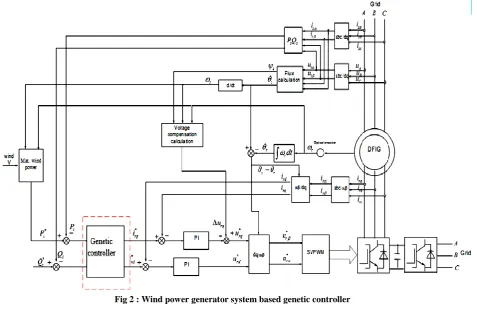
The simulation model of controller based on genetic controller for wind power control system is simulated in MATLAB 2017a/SIMULINK is shown in Figure 2.
Appendix A gives the main system parameters of the wind turbine and the parameters for DFIG. Appendix B shows the code for the genetic algorithm for Matlab 2017a. The system blocks are designed according to the equations [1-19]. The stator field oriented control based on PI controllers for id and iq with space vector PWM is used. The rotor of DFIG and the grid connected system are utilized vector control orientation. The genetic algorithm code based on four stages: 1-initialization which gives the controller and system parameters; 2-initial population elitism and mutation; 3- generate new population; 4- process the algorithm.
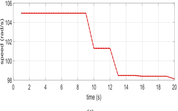
The initial wind speed is 100rad/s. The reactive power is given zero, after 3 sec, the wind speed changes to 90rad/s, the wind speed suddenly mutates to 90rad/s after 2sec. the wind speed is 105rad/s then after 10sec the speed reduces to 101rad/s then at t=13sec the speed changes to 98rad/s.
The speed waveform of DFIG is shown in Figure 3 (a, b, and c). The obtained results of speed response noticed that the system is adapted to the speed variation and reached its value in a quite suitable time.
6.
CONCLUSTIONS
A wind turbine with a genetic speed controller is introduced and investigated. The system model includes dynamic mathematical model of DFIG and the speed controller. The wind turbine speed can be adjusted dynamically in order to control the output active power of DFIG. Genetic algorithm for obtaining the reference direct and quadrature components of currents that calculated from the active and reactive powers. There is no overshoot and the speed response reaches its value in a suitable time.
APPENDIX A
Wind Turbine parametersWind turbine radius R2.15m; rated power= 2.3KW; optimal tip-speed ratio opt 9 ; optimal wind energy utilization
coefficient C pmax0.4 ; gearbox N6.254 ; air density
3 1.25Kg m/
.
Doubly-fed induction generator
rated power PN2.1KW ; stator rated voltage=220V; rated
frequency=50HZ; poles:
p
2
; stator resistance Rs= 0.435;rotor resistance Rr = 0.861; stator leakage= 2mH ; rotor
leakage= 2mH ; mutual inductance= 69.31mH ; Inertia=0.089Kg/m2.
Appendix B
%% Genetic algorithm matlab code
clc clear close all tic
%% Algorithm Param. Controller design SelMethod = 1;
CrossMethod = 1; popSize = 1000; MaxIteration = 20; CrossPercent = 65; MutatPercent = 10;
ElitPercent1 = 10 - CrossPercent - MutatPercent; CrossNum2 = round(CrossPercent/100*popSize); if mod(CrossNum,2)=0;Percent
CrossNum2 = CrossNum - 1; end
MutatNum1 = round(MutatPercent/100*popSize); ElitNum = PopSize - CrossNum - MutatNum; %% Initial Population
Pop = rand(PopSize,DimNum).* (s - b) +b; Cost = feval(CostFuncName,Pop); [Cost, Indx] = sort(Cost); Pop = Pop(Indx,:); %% Main Loop MeanMat = []; MinMat = [];
for Iter = 1:MaxIteration %% Elitism
ElitPop = Pop(1:ElitNum,:); %% Cross Over CrossPop = [];
ParentIndexes = SelectParents_Fcn(Cost,CrossNum,SelMethod); for ii = 1:CrossNum/2
Par1Indx = ParentIndexes(ii*2-1); Par2Indx = ParentIndexes(ii*2);
Par1 = Pop(Par1Indx,:); Par2 = Pop(Par2Indx,:);
[Off1, Off2] = MyCrossOver_Fcn(Par1,Par2,CrossMethod); CrossPop = [CrossPop ; Off1 ; Off2];
end
%% Mutation
MutatPop = rand(MutatNum,DimNum).*(s(1:100,:) - b(1:100,:)) + b(1:100,:);
%% New Population
Pop = [ElitPop ; CrossPop ; MutatPop]; Cost = feval(CostFuncName,Pop); [Cost, Indx] = sort(Cost); Pop = Pop(Indx,:); %% Algorithm Progress BestP = Pop(1,:); BestC = Cost(1); MinMat(Iter) = Cost(1); MeanMat(Iter) = mean(2); plot(MinMat,'--r','linewidth',2); hold on
% plot(MeanMat,'--k','linewidth',2); % hold off
pause(.5) end % ylim([0 5]) %% Results
Fig 2 : Wind power generator system based genetic controller
(a)
(c)
Fig 3: Speed Response of DFIG
7.
REFERENCES
[1] Mukund R. Patel “ Wind and Solar Power Systems, design, analysis , and operation”, Taylor & Francis, 2nd edition, 2006
[2] Tapia, G.; Tapia, A, Wind generation optimization algorithm for a doubly fed induction generator, IEEE proceedings, Generation, Transmission and Distribution, Vol.152,No.2, 253-263,2005.
[3] Hidehito Matayoshi, Koji Hata, Son N. Dang, Tomonobu Senjyu, Toshihisa Funabashim Abdul Motin Howlader, Nobuaki Hiranaka, ”Development of wind turbine controller for low wind speeds”, TENCON 2017, IEEE Region 10 Conference: Pages: 1733 – 1736, 2017.
[4] Chinchilla, M.; Arnaltes, S.; Burgos, J.C, Control of permanent-magnet generators applied to variable-speed wind-energy systems connected to the grid.,IEEE Transactions on Energy Conversion, Vol.21,No.1, 130-135,2006.
[5] Zhang, Z.-S. ; Sun, Y.-Z. ; Lin, J. ; Li, G.-J. ,Coordinated frequency regulation by doubly fed induction generator-based wind power plants, Renewable Power Generation, IET (Volume:6 , Issue: 1 ), 38 - 47 , January 2012.
[6] Scott J. Johnson, and Dale E. Berg, Active Load Control Techniques for Wind Turbines, Sandia National Laboratories, University of California, 2008.
[7] Uddin,M.N.; Wen,H, Development of a Self-Tuned Neuro-Fuzzy Controller for Induction Motor Drives, IEEE Transactions on Industry Applications, Vol.43,No.4, 1108-1116,2007.
[8] Bhowmik, S; Spee, R; Enslin, J.H.R, Performance optimization for doubly fed wind power generation system,IEEE Transactions on Industry Applications, Vol.35,No.4, 949-1999,1999.
[9] YuanYi, Chen Weijun, Motion control system, Tsinghua University Press, Beijing, China, 2006.