Accepted Manuscript
Composite Risers for Deep Waters Using a Numerical Modelling Approach
Chiemela Victor Amaechi, Gillett Nathaniel, Charles Odijie Agbomerie, Xiaonan Hou, Jianqiao Ye
PII: S0263-8223(18)30264-2
DOI: https://doi.org/10.1016/j.compstruct.2018.11.057
Reference: COST 10422
To appear in: Composite Structures
Received Date: 16 February 2018
Revised Date: 8 November 2018
Accepted Date: 21 November 2018
Please cite this article as: Amaechi, C.V., Nathaniel, G., Agbomerie, C.O., Hou, X., Ye, J., Composite Risers for Deep Waters Using a Numerical Modelling Approach, Composite Structures (2018), doi: https://doi.org/10.1016/ j.compstruct.2018.11.057
*Correspondence author: [email protected]
Composite Risers for Deep Waters Using a Numerical Modelling Approach
Chiemela Victor Amaechi1,3, Gillett Nathaniel1, Charles Odijie Agbomerie2, Xiaonan Hou1, Jianqiao Ye1,*
1
Engineering Department, Lancaster University, Lancaster, LA1 4YR, UK.
2
Continental, ContiTech Industrial Fluid System, Dunlop Oil and Marine Limited, Grimsby, DN31 2SY, UK.
3
Standards Organisation of Nigeria (SON), Wuse Zone 7, Abuja, Nigeria.
Abstract
There has been an increase in the application of composite structures in the oil and gas industry over the past four decades. This is due to more technological advancement and an increase in demand for the oil and gas. This trend has led to offshore exploration to transit from shallow water to deep water operations. Thus the need for more lightweight composite structures to reduce the deck loads and enable ease of operation. Composite risers are important as the properties of composite materials can be harnessed to improve riser performance and weight. This will enhance the development of deep water hydrocarbon reservoirs. In this paper, numerical stress analysis of composite offshore risers for deep water applications is carried out. ANSYS ACP is used for the finite element modelling of the composite riser for six load cases. From the design, recommendations for the design of the composite riser are made.
Keywords: Composite Riser, Finite Element Model, Composite Tube, Offshore Engineering, Numerical Modelling, Stress Distribution
1.0 Introduction
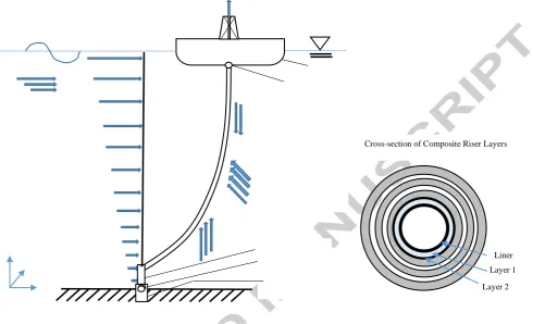
The current demand for oil and gas has led to an increase in more technological advancements in the petroleum industry. This trend has resulted in offshore exploration to move from shallow waters to deep waters. This requires longer risers, resulting in significant weight increase. To improve riser performance, composite materials may be used. The composite materials offer advantages that can be harnessed within a riser design. The advantages include high corrosion resistance, fatigue resistance, high strength characteristics and increased weight savings. Thus, the composite structure becomes lightweight with low bending stiffness. Generally, marine risers are not independent structures, as they depend on other offshore structures like platforms and semisubmersibles (Odijie, Wang, et al. 2017; Odijie, Quayle, et al. 2017). The behaviour of composite risers in water, as offshore-dependent structures, are subject to environmental loads (Amaechi et al. 2018; DNVGL 2017). In order to design a composite riser, these loads must be carefully considered. Figure 1 shows the typical structure of a composite riser, describing the different loads that act on it. A cross-section of the layers of the composite riser is also illustrated to show the composite make-up of the layers.
*Correspondence author: [email protected]
designs have been made over the past three decades (Wang et al. 2015; Ochoa & Salama 2005; Pham et al. 2016; Amaechi & Ye 2017). Previous research by joint industry presented the mechanical properties of composite tubes (Tamarelle & Sparks 1987; Sparks et al. 1988; Sparks et al. 1992; Salama 1986) and composite production risers for different design load cases (Baldwin et al. 1997; Salama et al. 1999; Baldwin et al. 2002; Johnson et al. 1999). Later, Doris Engineering presented a composite riser that introduced off-axis reinforcements at an angle of +/-55° in order to reduce riser weight and improve efficiency (Picard et al. 2007). In this study, netting theory was used. This assumes that the fibres in each layer are load-bearing, but that no stresses are present in the transverse direction. They concluded that the optimum angle for the design is +/-54.7°. This has led to advances in the modelling techniques like homogenization (Sun et al. 2013; Sun et al. 2014; Bhudolia et al. 2015; Akula 2014; Tan et al. 2015). Advances relating to strength performance, debonding and delamination issues and riser components like the metal-composite interface (MCI) and end-fitting also exist in the literature (Kim 2007; Wang et al. 2017; Rasheed & Tassoulas 1995; Ochoa et al. 2007; Ochoa & Technology 2006). Composite riser design concepts have been established by Airborne and Magma. Airborne developed thermoplastic composite pipes for offshore applications in deep waters (Echtermeyer & Steuten 2013; Smits et al. 2018; Onna & O’Brien 2011). Magma has developed the M-pipe, a composite pipe which can be used in various applications (Wilkins 2016; Hatton et al. 2013). According to Hatton (2012), composite risers are an enabling technology, thus requiring qualification. Some qualification experience on composite riser are presented in literature (Drey et al. 1997; Baldwin et al. 1998; Hatton et al. 2013; Johnson et al. 1998). However, qualification of deep water composite risers is still an issue in the industry. This necessitates the need to improve these designs through optimization (Sonmez 2017; Ghiasi et al. 2010; Ghiasi et al. 2009). Harte et al. (2001, 2003) optimised a composite pipeline joint to reduce both the weight and peak stresses using a safety factor of 4.5. Fernandes da Silva et al. (2013) presented another methodology for the optimization of composite risers using a Genetic Algorithm. Wang et al. (2016) optimised a composite riser design using a surrogate-assisted evolutionary algorithm. The technique was applied to consider some critical load cases and thus reduce the structural weight. Manual tailoring of composite materials was carried out by using multiple variables to reduce the Finite Element Analysis (FEA). This resulted in a weight saving of 25% compared to the conventional method. Current optimized designs are presented in literature (Jha et al. 2016; Teófilo et al. 2013; Wang et al. 2016; Teófilo et al. 2010). Some prototype designs of composite risers are also presented in some literature (Andersen et al. 1998; Chen et al. 2016).
*Correspondence author: [email protected]
of composite risers and support the deployment of composite risers and tubes in the offshore industry.
2.0 The Design 2.1 Design Approach
The design considered in this paper is for a 2,000m deep water riser using the parameters in Table 1. The tension calculation for the riser considers the effective weight of the riser based on the wall thickness used. Three approaches are considered in the design of the composite riser: the analytical design, conventional design and the numerical design. The analytical design is used to derive the constitutive model for the composite riser. The conventional design is based on the orthogonal design of composites, where laminate reinforcements are arranged
in only axial and hoop directions. In this method, the plies are in the orientations of 0o and 90o.
The reinforcements of the composite riser are designed in axial, angled and hoop directions. The mechanical properties of the composite materials considered are presented in Table 2. Different liner materials are also applied, as given in Tables 3. In addition, the stack-up sequence for the plies and the fibre orientations for the body of the composite riser are considered in the design, as given in Table 4. The design process starts with the design of the composite riser geometry in Design Modeler in ANSYS 19.0. Next, a Mechanical Model is developed in ANSYS Workbench. The Engineering Data are then developed and the model set up. It is then connected to the Static Structural model. Another setup using the same geometry with different liner thickness is developed. Next, an ACP (Pre) model is set-up and the material properties are developed. Then, the ACP (Post) model is also developed for the post-processing. The ACP (Pre) is then connected both the Static Structural model and the ACP
Weight of Compositeriser Wave forces
Current forces
Z
Y
X Foundationcasing
Internal and external fluidpressure
Buoyancy
Mean Water Level Vessel
TopConnection /Tensioner
[image:4.595.43.534.114.412.2]Bottomconnection Stress Joint
Figure 1 Composite Riser System showing loads and cross-section of the layers
Cross-section of Composite Riser Layers
Liner
Layer 1
*Correspondence author: [email protected]
(Post) model. Different design cases for the 6 loading conditions are considered. This process is carried out to get the best model for the design. The axial, off-axis and hoop reinforcements are all considered in the design procedure as presented. The initial design variables are first inputted. Next, the FEA is carried out using these values. The off-axis (angled) plies was determined as +53.5° using Netting Theory (Evans & Gibson 2002; Tew 1995; Carey & Mertiny 2013; DOD 2002; Gillett 2018). However, the design was optimized as presented in Section 3.5. A maximum stress criterion is used to determine the layers/lamina that fail due to stresses exceeding the lamina strengths. This is used in calculating the Factor of Safety (F.S) for each of the layers.
2.2 Material Properties
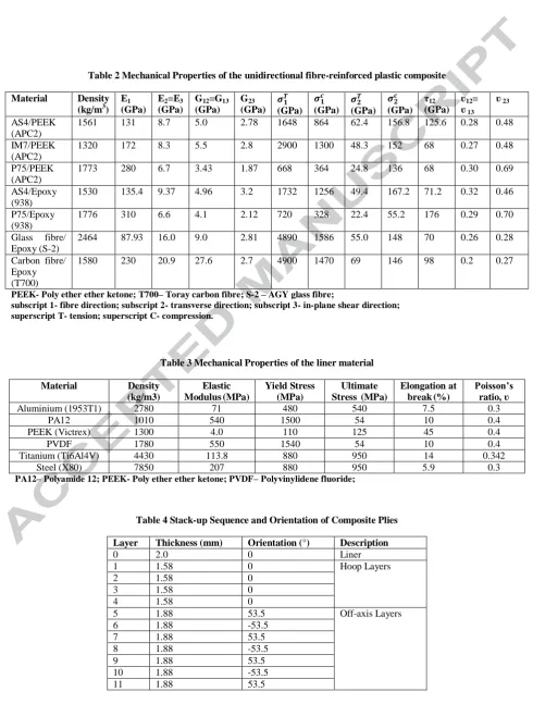
The parameters of the geometry were determined in the design stage as given in Table 1. Other important details include the thickness of the laminate layers, the stacking sequence, the liner thickness and the orientations of the fibre. High-performance materials are considered for both the fibre and matrix combinations. The reinforcement material considered for the fibres is high-strength AS4 carbon fibre. Two additional matrix materials that are considered in this study are the thermoplastic- PEEK, and the thermoset- Epoxy. The unidirectional lamina materials used in the Finite Element Analysis are PEEK composites. The PEEK material properties are used for the FEA analysis by considering the properties of the composite material. The properties for
the Poisson’s ratios (ʋ1, ʋ2 and ʋ3), the elastic moduli (E1, E2 and E3) and the shear moduli (G12,
G13 and G23) are presented in Table 2. The subscripts 1 and 2 represent fibre and transverse
directions, respectively. Subscript 12 represent the in-plane shear direction.
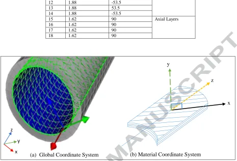
Generally, material properties of composites depend on conditions like the static loads, time, temperature, chemicals, water (Jones 1999; Kaw 2006; Ye 2003). This affects the characteristic length of the composite structure. The material coordinate, also known as the rosette, is in XYZ coordinate system. Figure 2 represents the global and material coordinate systems of the composite riser. Different layers have different material coordinates, and this was considered in the design in ANSYS ACP. In the global coordinate, the z-axis lies along the length of the composite riser, as shown in Figure 2 (a). The material coordinate, also known as the rosette, is in XYZ coordinate system. The material coordinate is relative to the fibre direction in x-axis, as shown in Figure 2 (b). The wall of the composite riser is considered a thick-walled pipe in the design and analysis. The materials are modelled by considering the mechanical behaviour of these materials. The composite riser also has in-plane effective properties and other material properties. Details of the material properties used in this investigation are presented in Tables 2 and 3. These data were extracted from technical sources (MatWeb 2018; Toray 2008; Hartman et al. 1996; Wang et al. 2017).
Table 1 Composite Riser Parameters
Parameter Value
*Correspondence author: [email protected]
[image:6.595.56.547.120.768.2]Water Depth (m) 2000
Table 2 Mechanical Properties of the unidirectional fibre-reinforced plastic composite
Material Density (kg/m3)
E1 (GPa)
E2=E3 (GPa)
G12=G13 (GPa)
G23
(GPa) (GPa) (GPa) (GPa) (GPa) τ12 (GPa)
ʋ12= ʋ 13
ʋ 23
AS4/PEEK (APC2)
1561 131 8.7 5.0 2.78 1648 864 62.4 156.8 125.6 0.28 0.48
IM7/PEEK (APC2)
1320 172 8.3 5.5 2.8 2900 1300 48.3 152 68 0.27 0.48
P75/PEEK (APC2)
1773 280 6.7 3.43 1.87 668 364 24.8 136 68 0.30 0.69
AS4/Epoxy (938)
1530 135.4 9.37 4.96 3.2 1732 1256 49.4 167.2 71.2 0.32 0.46
P75/Epoxy (938)
1776 310 6.6 4.1 2.12 720 328 22.4 55.2 176 0.29 0.70
Glass fibre/ Epoxy (S-2)
2464 87.93 16.0 9.0 2.81 4890 1586 55.0 148 70 0.26 0.28
Carbon fibre/ Epoxy (T700)
1580 230 20.9 27.6 2.7 4900 1470 69 146 98 0.2 0.27
PEEK- Poly ether ether ketone; T700– Toray carbon fibre; S-2 – AGY glass fibre;
subscript 1- fibre direction; subscript 2- transverse direction; subscript 3- in-plane shear direction; superscript T- tension; superscript C- compression.
Table 3 Mechanical Properties of the liner material
Material Density
(kg/m3)
Elastic Modulus (MPa)
Yield Stress (MPa)
Ultimate Stress (MPa)
Elongation at break (%)
Poisson’s ratio, ʋ
Aluminium (1953T1) 2780 71 480 540 7.5 0.3
PA12 1010 540 1500 54 10 0.4
PEEK (Victrex) 1300 4.0 110 125 45 0.4
PVDF 1780 550 1540 54 10 0.4
Titanium (Ti6Al4V) 4430 113.8 880 950 14 0.342
Steel (X80) 7850 207 880 950 5.9 0.3
[image:6.595.62.547.140.420.2]PA12– Polyamide 12; PEEK- Poly ether ether ketone; PVDF– Polyvinylidene fluoride;
Table 4 Stack-up Sequence and Orientation of Composite Plies
Layer Thickness (mm) Orientation (°) Description
0 2.0 0 Liner
1 1.58 0 Hoop Layers
2 1.58 0
3 1.58 0
4 1.58 0
5 1.88 53.5 Off-axis Layers
6 1.88 -53.5
7 1.88 53.5
8 1.88 -53.5
9 1.88 53.5
10 1.88 -53.5
*Correspondence author: [email protected]
x z y
(b) Material Coordinate System (a) Global Coordinate System
12 1.88 -53.5
13 1.88 53.5
14 1.88 -53.5
15 1.62 90 Axial Layers
16 1.62 90
17 1.62 90
18 1.62 90
2.3 Design Load Cases
[image:7.595.65.531.73.389.2]The load that acts on a typical composite riser are as depicted in Figure 1. In Table 5, six (6) different local design load cases are considered. The burst case (load case 1) is the critical load case and is therefore first investigated. The load cases implemented are recommended in industry standards on composite riser design (ABS 2014; DNVGL 2015; DNV 2010b; DNV 2010a). The factor of 2.25 applied is according to test results as specified in ABS (2014) as the ultimate tension strength of composite risers. The design load cases are carried out by considering the different stress components on the different fibre orientations. The stress distributions obtained based on these design load conditions are presented in Section 3.4.
Table 5 Design Load Cases for Composite Riser
Load Case Name Description
Load Case 1 Burst Case with end load effect An internal pressure of 155.25 MPa is applied Load Case 2 Collapse Case An external pressure of 60 MPa is applied Load Case 3 Pure Tension Case The load factor of 2.25 with maximum tension
[image:7.595.58.532.618.698.2]Load Case 4 Internal Pressure and Tension Case An internal pressure of 155.25MPa is applied on the tension Load Case 5 External Pressure and Tension Case The load factor of 2.25 is applied on 19.5MPa external pressure Load Case 6 Buckling Case An external pressure of 60 MPa is applied
Figure 2 The coordinate system for the composite riser showing the material rosette
*Correspondence author: [email protected] 3.0 Numerical Model
3.1 Finite Element Model
The Finite Element (FE) model of the 3m composite riser is developed in ANSYS ACP. The parameters for the composite riser is given in Table 1. The fixed end boundary condition is considered at both ends to represent the closed pipe during operation and test conditions as given in ABS standard (2014). Solid 186 elements are used as 3D layered structural solid elements. This type of element supports quadratic displacements and also exhibits translation motion in three degrees of freedom about its 20 nodes. Solid 186-layered elements are deployed in simulating the laminates of the composite riser, whereas Solid 186-homogenous elements are used for simulating single elements like the liners in the radial direction. The solver applies the thickness of the element using the nodal coordinates. This assists in modelling the stack-up of the laminates and the modelling plies. Thus, the complete layup is developed in the defined material coordinate called the rosette. The methodology for the loca l design involved using the load cases to obtain stress values for each composite layer for different thicknesses. Details on some theories on the stresses are available in literature (Ye, 2016; 2003). The first step in the finite element analysis is to predict the riser behaviour, with some initial values estimated for the composite layers. The burst case is carried out with a 155.25 MPa internal pressure by considering the boundary condition at the fixed end supports. This represents the actual test scenario for testing composite risers, composite tubes and composite pipes for offshore applications. The stresses were obtained from selected element location on the composite riser.
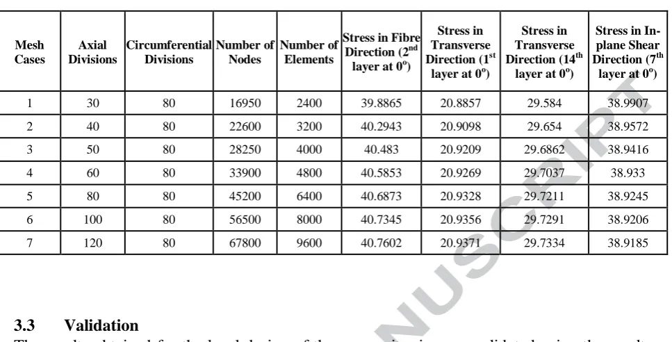
In the FEA, a quadrilateral mesh type is applied. The FEA model is designed with 30 axial divisions and 80 circumferential divisions, involving 16,950 nodes and 2,400 elements. The composite riser is analysed as a shell body in ANSYS ACP 19.0. Multiple material layup configurations are designed with 18 layers considered in each CPR design. Different liner materials are used in conducting the analysis for each case study. In this design, the axis for the layers for the material as designed from outer layer to inner layer, is shown in Figure 2 (a). The finite element model showing the stack-up for the materials for the composite riser with
[04,(±53.5)5,904] configuration in ANSYS ACP (Pre) is as illustrated in Table 4.
3.2 Convergence Study
[image:9.595.62.546.85.331.2]
*Correspondence author: [email protected]
Table 6 Mesh Study used in Finite Element Analysis
Mesh Cases
Axial Divisions
Circumferential Divisions
Number of Nodes
Number of Elements
Stress in Fibre Direction (2nd
layer at 0o)
Stress in Transverse Direction (1st
layer at 0o)
Stress in Transverse Direction (14th
layer at 0o)
Stress in In-plane Shear Direction (7th layer at 0o)
1 30 80 16950 2400 39.8865 20.8857 29.584 38.9907
2 40 80 22600 3200 40.2943 20.9098 29.654 38.9572
3 50 80 28250 4000 40.483 20.9209 29.6862 38.9416
4 60 80 33900 4800 40.5853 20.9269 29.7037 38.933
5 80 80 45200 6400 40.6873 20.9328 29.7211 38.9245
6 100 80 56500 8000 40.7345 20.9356 29.7291 38.9206
7 120 80 67800 9600 40.7602 20.9371 29.7334 38.9185
3.3 Validation
[image:10.595.123.531.78.272.2]
*Correspondence author: [email protected]
Figure 3 Validation of Model with Wang’s model under Burst Case in fibre direction for AS4/Epoxy with Aluminium liner using a factor of safety of composite layers reinforced using [04,(±53.5)5,04] configuration
3.4 Result Analysis and Discussion
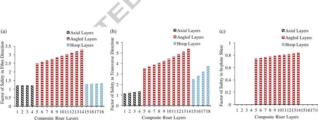
Figures 4 (a-i) and 5 (a-f) are the results for the design loads for the composite riser as presented in Section 2.3. The composite structure was modelled in ANSYS ACP using a 3D-element as presented in Section 3.1. Results are obtained for the stress components in the fibre,
transverse and in-plane shear directions.As these results were below the minimum safety factor
of 1, the design satisfied the requirements as detailed in the ABS standard (2014). The design must be optimised in order to have composite riser structure with better performance as presented in Section 3.5. The Factor of Safety was then obtained using the strength values in Table 2 and Equation (1);
( )
Figures 4 (a-c) shows the results for the burst load; Figure 4 (d-f) shows the results for the collapse load; Figure 4 (g-i) shows the results for the pure tension load; Figure 5 (a-c) shows the results for the tension with internal pressure load while Figure 5 (d-f) shows the results for
the tension with external pressure load. The composite riser is designed using AS4/Epoxy and 2
mm thick titanium liner is applied with [04,(±53.5)5,904] configuration. An internal pressure of 155.25MPa is applied in the burst case with end effect. For the collapse case, an external pressure of 60 MPa is applied. This design cases determine the performance of the layers. However, the ability of each layer to withstand the internal pressure is also dependent on the liner. The burst load case with end effect was first carried out to determine the thickness of the composite riser. It also shows the critical performance characteristics of the composite riser.
In Figure 5 (g-i), the effect of tension force on the fibres during installation is also investigated. Two tension cases were used: 4,580KN and 7620KN loads are applied in tension case 1 and case 2 respectively. The investigation is carried out for a composite riser of 18 layers. Burst
load was applied using AS4/Epoxy and Aluminium liner with [04,(±53.5)5,904] configuration.
As is observed in Figure 5 (g-i), an increase in the tension force decreases the Factor of Safety in the axial layers and hoop layers but increases the Factor of Safety in the off-axis layers. This
0 0.5 1 1.5 2 2.5 3 3.5 4 4.5
1 2 3 4 5 6 7 8 9 10 11 12 13 14 15 16 17 18
F
ac
to
r
o
f
S
af
et
y
in
F
ibr
e
D
ir
ec
ti
o
n
Composite Riser Layers Present Model
*Correspondence author: [email protected]
means that, as the tension increases, the stresses on the axial and hoop layers increase while the stresses decrease at the off-axis layers. The tension ratio for both cases investigated is 1:1.7. Considering the fibre direction, the axial layers had a 25.8% decrease in the Factor of Safety. In the off-axis layers, there is an 11.7% increase in the Factor of Safety. In the hoop layers, there is a 5% decrease in the Factor of Safety. This means that, the off-axis is properly reinforced to carry the tension force in the fibre direction. Looking at the transverse direction, the axial layers had a 4.4% increase in the Factor of Safety. In the off-axis, there is 25% decrease in the Factor of Safety. In the hoop axis, there is 27.3% decrease in the Factor of Safety. From these, we can conclude that an increase in the tension force will increase the stresses in the off-axis and hoop layers, implying a decrease in their Factors of Safety, respectively. Considering the In-plane shear direction, the Factors of Safety in both the axial and the hoop layers are infinity as they are negligible but not exactly zero, as shown in Figure 5 (c, f, i). In the off-axis layers, there is a 16.8% increase in the Factor of Safety. Thus an increase in tension will decrease the stresses in the off-axis layers in the in-plane shear direction.
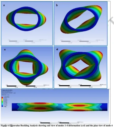
[image:11.595.23.579.422.633.2]In Figure 6 (a-e), different modes on the buckling analysis carried out on the CPR design are presented. An external pressure of 60 MPa is applied using linear buckling analysis. Figure 6 (a-d) is the end view for different mode shapes for modes 1-4 while Figure 6 (e) shows a plan view of mode 4. Mode 1 has the most critical buckling effect for the CPR design (Gillet, 2018). Table 7 presents the maximum deformations, axial waves and circumferential waves obtained. From the results, Modes 1 and 2 have the critical buckling pressure of 75.6 MPa is approximately 30% higher than the design buckling pressure of 60 MPa. It is noteworthy that the mode shapes are not shown in true scale of the deformation but with a relative scale factor for visualization. 0 0.5 1 1.5 2 2.5 3 3.5
1 2 3 4 5 6 7 8 9 10 11 12 13 14 15 16 17 18
F a ct o r o f S a fe ty i n F ib re D ire ct io n
Composite Riser Layers
(a) Axial Layers
Angled Layers Hoop Layers 0 1 2 3 4 5 6
1 2 3 4 5 6 7 8 9 10 11 12 13 14 15 16 17 18
F a ct o r o f S a fe ty i n T ra n sv ers e D ire ct io n
Composite Riser Layers
(b) Axial Layers
Angled Layers Hoop Layers 0 0.2 0.4 0.6 0.8 1
1 2 3 4 5 6 7 8 9 10 11 12 13 14 15 16 17 18
F a ct o r o f S a fe ty i n In -p la n e S h ea r
Composite Riser Layers
(c) Axial Layers
[image:12.595.27.579.67.408.2]
*Correspondence author: [email protected]
Figure 4 Factor of Safety profiles for the layers of the composite riser using AS4/Epoxy and titanium liner with [04,(±53.5)5,904] configuration under: i)
burst load case in (a) Fibre Direction, (b) Transverse Direction, (c) In-plane Shear Direction; ii) collapse load case in (a) Fibre Direction, (b) Transverse Direction, (c) In-plane Shear Direction; and iii) pure tension load case in (a) Fibre Direction, (b) Transverse Direction, (c) In-plane Shear Direction.
0 1 2 3 4 5 6 7
1 2 3 4 5 6 7 8 9 10 11 12 13 14 15 16 17 18
F a ct o r o f S a fe ty i n F ib re D ire ct io n
Composite Riser Layers
(a) Axial Layers
Angled Layers Hoop Layers 0 2 4 6 8 10 12 14 16 18
1 2 3 4 5 6 7 8 9 10 11 12 13 14 15 16 17 18
F a ct o r o f S a fe ty i n T ra n sv ers e D ire ct io n
Composite Riser Layers
(b) Axial Layers
Angled Layers Hoop Layers 0 0.5 1 1.5 2 2.5
1 2 3 4 5 6 7 8 9 10 11 12 13 14 15 16 17 18
F a ct o r o f S a fe ty i n In -p la n e S h ea r
Composite Riser Layers
(c) Axial Layers
Angled Layers Hoop Layers 0 2 4 6 8 10
1 2 3 4 5 6 7 8 9 10 11 12 13 14 15 16 17 18
F a ct o r o f S a fe ty i n F ib re D ire ct io n
Composite Riser Layers
(a) Axial Layers
Angled Layers Hoop Layers 0 2 4 6 8 10 12
1 2 3 4 5 6 7 8 9 10 11 12 13 14 15 16 17 18
F a ct o r o f S a fe ty i n T ra n sv ers e D ire ct io n
Composite Riser Layers
(b) Axial Layers
Angled Layers Hoop Layers 0 0.5 1 1.5 2
1 2 3 4 5 6 7 8 9 10 11 12 13 14 15 16 17 18
F a ct o r o f S a fe ty i n In -p la n e S h ea r
Composite Riser Layers
(c) Axial Layers
Angled Layers Hoop Layers 0 1 2 3 4 5 6 7 8
1 2 3 4 5 6 7 8 9 10 11 12 13 14 15 16 17 18
F a ct o r o f S a fe ty i n F ib re D ire ct io n
Composite Riser Layers
(a) Axial Layers
Angled Layers Hoop Layers 0 0.5 1 1.5 2 2.5 3
1 2 3 4 5 6 7 8 9 10 11 12 13 14 15 16 17 18
F a ct o r o f S a fe ty i n T ra n sv ers e D ire ct io n
Composite Riser Layers
(b) Axial Layers
Angled Layers Hoop Layers 0 1 2 3 4 5 6
1 2 3 4 5 6 7 8 9 10 11 12 13 14 15 16 17 18
F a ct o r o f S a fe ty i n In p la n e S h ea r
Composite Riser Layers
(c) Axial Layers
[image:13.595.29.577.70.435.2]
*Correspondence author: [email protected]
Figure 5 Factor of Safety profiles for the layers of the composite riser configured with AS4/Epoxy and [04,(±53.5)5,904] configuration under: i) tension with
internal pressure load case using titanium liner in (a) Fibre Direction, (b) Transverse Direction, (c) In-plane Shear Direction; ii) tension with external pressure load case using titanium liner in (d) Fibre Direction, (e) Transverse Direction, (f) In-plane Shear Direction; and iii) burst load case with end load effect using aluminium liner to investigate the effect of tension force during installation in (g) Fibre Direction, (h) Transverse Direction, (i) In-plane Shear Direction. 0 2 4 6 8 10 12
1 2 3 4 5 6 7 8 9 10 11 12 13 14 15 16 17 18
F a ct o r o f S a fe ty i n F ib re D ire ct io n
Composite Riser Layers
(d) Axial Layers
Angled Layers Hoop Layers 0 0.5 1 1.5 2 2.5 3 3.5 4 4.5
1 2 3 4 5 6 7 8 9 10 11 12 13 14 15 16 17 18
F a ca to r o f S a fe ty i n T ra n sv ers e D ire ct io n
Composite Riser Layers
(e) Axial Layers
Angled Layers Hoop Layers 0 0.2 0.4 0.6 0.8 1
1 2 3 4 5 6 7 8 9 10 11 12 13 14 15 16 17 18
F a ct o r o f S a fe ty i n In -p la n e S h ea r
Composite Riser Layers
(f) Axial Layers
Angled Layers Hoop Layers 0 1 2 3 4
1 2 3 4 5 6 7 8 9 10 11 12 13 14 15 16 17 18
F a ct o r o f S a fe ty i n F ib re D ire ct io n
Composite Riser Layers
(g)
Tension case1 [4,580KN]
Tension case2 [7,620KN]
0 1 2 3 4 5 6
1 2 3 4 5 6 7 8 9 10 11 12 13 14 15 16 17 18
F a ct o r o f S a fe ty i n T ra n sv ers e D ire ct io n
Composite Riser Layers
(h)
Tension case1 [4,580KN]
Tension case2 [7,620KN]
0 0.2 0.4 0.6 0.8 1
1 2 3 4 5 6 7 8 9 10 11 12 13 14 15 16 17 18
F a ct o r o f S a fe ty i n In p la n e S h ea r
Composite Riser Layers
(i)
Tension case1 [4,580KN]
[image:14.595.69.527.68.578.2]
*Correspondence author: [email protected]
Figure 6 Eigenvalue Buckling Analysis showing end view of modes 1-4 deformation (a-d) and the plan view of mode 4 deformation (e), in ANSYS 19.0, relatively scaled for visualization
Table 7 Results of the Eigenvalue buckling analysis
Results of Eigenvalue Buckling Analysis
Mode 1 2 3 4
Buckling Pressure (MPa) 75.6 75.6 76.8 76.8
Number of Axial Half-Waves 1 1 2 2
Number of Circumferential Waves 2 2 2 2
[image:14.595.90.518.641.706.2]
*Correspondence author: [email protected] 3.5 Optimisation
The results obtained from the design load cases in Section 3.4 were further analysed to obtain an optimal design. Different design concepts were considered in this section. The purpose of the optimisation is to reduce the material utilised, reduce the weight of the composite riser and also ensure that the strength of the composite riser can withstand the different design load cases. To optimise the composite riser design, some considerations for the optimisation are presented in Sections 3.5.1 - 3.5.5. The parameters considered are the thickness of the fibre layers, thickness of the hoop layers, thickness of the off-axis layers, type of liner material, thickness of liner material, type of composite material, the number of layers, and the orientation of the layers.
3.5.1 Consideration 1: Different liner materials
Figures 7 (a-f) represents the stress distribution for the effect of liners on the AS4/Epoxy
composite riser designed using [04,(±53.5)5,904] configuration. The effect of different liner
materials is investigated on six (6) different liner materials: PA12, steel, Titanium, Aluminium,
PVDF and PEEK liners are analysed. The same liner thickness of 2 mm and layer thickness ratio
of 1.58:1.62:1.86 were applied for all the cases. For the analysis, PA12 liner had the least stress values in all the stress components. This means, that newer liner designs can be carried out using the PA12 material, as this also has good liner properties for composite riser applications, as seen in Figure 7 (a). Steel liner performed better than titanium liner. In Figure 7 (b), the PEEK liner and the PVDF liner were approximately the same stress, with the maximum stress value of 1450.99 MPa at the hoop layers in fibre direction.
3.5.2 Consideration 2: Layer Thickness
Figures 8 (a-c) represents the stress distribution for the effect of axial layer thickness on AS4/Epoxy composite riser with Aluminium liner. Two cases were compared with same
configuration [04,(±53.5)5,904] but layer thickness ratio of 1.58:1.62:1.86 and 1.64:1.62:1.86
respectively. The compared cases show that the higher the axial layer thickness, the less the stress distribution in the axial layers in the fibre direction. However, this increases the stresses in the off-axis layers and the hoop layers. Thus, the axial layers will withstand more stresses in the fibre direction than in the other layers in the same stress component. This is due to the
alignment of the fibres in the 0o angle being axially laid along the composite riser body. In the
transverse direction, an increase in the thickness of the axial layer will increase the stress in axial layers but decrease the stresses in the off-axis layers and hoop layers. In the in-plane shear direction, an increase in the axial layer thickness decreases the stress in the off-axis layers.
Figures 8 (d-f) represents the stress distribution for the effect of off-axis layer thickness using
AS4/Epoxy with Aluminium liner with same configuration [04,(±53.5)5,904] Two cases were
*Correspondence author: [email protected]
increase in the thickness of the off-axis layer will decrease the stress in all the layers. In the in-plane shear direction, an increase in the axis layer thickness decreases the stress in the off-axis layers.
Figures 8 (g-i) represents the stress distribution for the effect of hoop layer thickness using
AS4/Epoxy with Aluminium liner with same configuration [04,(±53.5)5,904] Two cases were
analysed of layer thickness ratio 1.58:1.62:1.86 and 1.58:1.62:1.60 respectively. The compared cases show that the higher the hoop layer thickness, the higher the stress distribution in the axial layers in the fibre direction. However, this decreases the stresses in both the off-axis layers and the hoop layers. Thus, the hoop layers will withstand more stresses in the fibre direction than when the thickness is increased but not much, compared to other layers. Also, an increase in the thickness of the hoop layers in the transverse direction will decrease the stress in the axial layers but increase the stresses in both the off-axis layers and the hoop layers. In the in-plane shear direction, an increase in the hoop layer thickness increases the stress in the off-axis layers.
3.5.3 Consideration 3: Different composite materials
Different composite materials were also applied for the same configuration to ascertain the best
performance using [04,(±53.5)5,904] as the composite riser design configuration. They are
AS4/PEEK (APC2), IM7/PEEK (APC2), P75/PEEK (APC2), AS4/Epoxy (938), P75/Epoxy (938), Glass fibre/ Epoxy (S-2) and Carbon fibre/ Epoxy (T700). The mechanical properties of these composite materials are presented in Table 2. From the analysis, the best performance chosen was AS4/Epoxy (938), based on material weight and strength.
3.5.4 Consideration 4: Layer Orientations
Figure 9 (a-f) represents the stress distribution for the effect of off-axis layer orientation using AS4/Epoxy with Aluminium liner for different configurations. The following off-axis angles
were investigated: ±45°, ±50°, ±52°, ±53.5°, ±55°, ±56°, ±58°, ±60°, and ±63.5°. From the
results, the best performance was observed in ±63.5°. This was considered the best angle for
the optimum design. Also, the orientations of other layers were also investigated. The stress distribution for the effect of axial layer orientation and hoop layer orientation were also investigated. An increase in the fibre layer angle from 0° increase the stresses in the fibre, transverse and in-plane shear stress components. In the in-plane shear, the stress values in the axial layers also increases from zero. This implies that the strength property in the in-plane shear can be affected by an increase in the orientation of the fibre layers. Different orientations
were investigated, such as [(0)4,(±53.5)5,(90)4], [(0)4,(±53.5)5,(89)4] and [(0)4,(±53.5)5,(88)4]. The
*Correspondence author: [email protected] 3.5.5 Consideration 5: Number of Layers
Different designs were analysed during theoptimization of the composite riser layers. In Figure
10 (a-i), six configurations are presented under burst load case. They are [03,(±53.5)4,904],
[04,(±53.5)3,903], [04,(±53.5)4,904], [03,(±53.5)5,903], [04,(±53.5)5,903] and [03,(±53.5)5,904] design
configurations. They were compared with the [04,(±53.5)5,904] design presented on Figure 4 (a-c).
The [04,(±53.5)5,904] design performed better among the cases analysed for the number of layers.
However, the results from Figure 10 showed that an increase in the number of layers will reduce the stresses on the layers.
3.5.6 Optimised Design
An optimised design was obtained based on the considerations given in Sections 3.5.1-3.5.5.
The design configuration [04,(±63.5)5,904] is the optimised design selected as the optimised
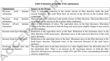
[image:17.595.62.526.359.615.2]design. An increase in the off-axis ply orientation reduced the stresses in the critical load case. Figure 9 shows different designs considered as using ±63.5° produced the least marginal stress profiles. Minimizing the thickness of the liner and hoop laminae was also considered. Thus, the thickness of the optimal design is 1.58:1.62:1.60. Table 8 gives a summary of the benefits of the optimisation process and its impact on the design.
Table 8 Summary of benefits of the optimisation
Optimisation Impact on the Design
Decrease axial laminae orientation
There is noticeable reduction in the tensile stresses in fibre direction under the pure tension load case. The axial fibres have an increase in the stresses in the in-plane shear component.
Decrease hoop laminae orientation
There is noticeable reduction in the tensile stresses in fibre direction. The hoop fibres have an increase in the stresses in the in-plane shear component.
Increase off-axis laminae orientation
There is redistribution of stress. The equivalent stress in the liner decreases. Maximum stress in the fibre direction in both the hoop and axial layers slightly change in non-critical off-axis laminae.
Increase axial layer thickness Reduction in the equivalent stress in the liner. Reduction in the maximum stress in the fibre direction of the hoop layers. Maximum stress in the transverse direction of the axial layers decrease.
Increase hoop layer thickness Reduction in the equivalent stress in the liner. Maximum stress in the fibre direction of the hoop layers decrease. Maximum stress in the transverse direction of the axial layers decrease.
Iteratively decrease liner and hoop laminae thickness
[image:18.595.60.559.132.632.2]
*Correspondence author: [email protected]
Figure 7 Stress profiles of composite riser design configured using AS4/Epoxy in [04,(±53.5)5,904] to investigate the effect of different
liner materials in the Fibre Direction (a, b); the transverse direction (c, d); and the in-plane shear direction (e, f). 0 200 400 600 800 1000 1200 1400
1 2 3 4 5 6 7 8 9 10 11 12 13 14 15 16 17 18
S tr es s in F ibr e D ir ec ti o n (M P a)
Composite Riser Layers
(a) PA12 liner
Steel liner Titanium liner 0 200 400 600 800 1000 1200 1400 1600
1 2 3 4 5 6 7 8 9 10 11 12 13 14 15 16 17 18
S tr es s in F ibr e D ir ec ti o n (M P a)
Composite Riser Layers
(b) Aluminium liner
PVDF liner PEEK liner 0 10 20 30 40 50 60 70 80
1 2 3 4 5 6 7 8 9 10 11 12 13 14 15 16 17 18
S tr es s in T ra ns v er se D ir ec ti o n (M P a)
Composite Riser Layers
(c) PA12 liner
Steel liner Titanium liner 0 10 20 30 40 50 60 70 80
1 2 3 4 5 6 7 8 9 10 11 12 13 14 15 16 17 18
S tr es s in T ra ns v er se D ir ec ti o n (M P a)
Composite Riser Layers
(d) Aluminium liner
PVDF liner PEEK liner 0 20 40 60 80 100 120
1 2 3 4 5 6 7 8 9 10 11 12 13 14 15 16 17 18
S tr es s in Inpl ane S he ar ( M P a)
Composite Riser Layers
(e) PA12 liner
Steel liner Titanium liner 0 20 40 60 80 100 120
1 2 3 4 5 6 7 8 9 10 11 12 13 14 15 16 17 18
S tr es s in Inpl ane S he ar ( M P a)
Composite Riser Layers
(f) Aluminium liner
[image:19.595.28.587.87.602.2]
*Correspondence author: [email protected]
Figure 8 AS4/Epoxy and Aluminium liner with [04,(±53.5)5,904] configuration of composite riser on the effect of: i) the axial layer thickness in the (a) Fibre
Direction, (b) Transverse Direction, (c) plane Shear Direction; ii) the off-axis layer thickness in the (d) Fibre Direction, (e) Transverse Direction, (f) In-plane Shear Direction; iii) and the hoop layer thickness in the (g) Fibre Direction, (h) Transverse Direction, and (i) In-In-plane Shear Direction.
0 200 400 600 800 1000 1200 1400
1 2 3 4 5 6 7 8 9 10 11 12 13 14 15 16 17 18
S tre ss i n F ib re D ire ct io n (M P a )
Composite Riser Layers
(a) Case 1 [(1.58)(1.62)(1.86)]
Case 2 [(1.84)(1.62)(1.86)]
0 10 20 30 40 50 60 70
1 2 3 4 5 6 7 8 9 10 11 12 13 14 15 16 17 18
S tre ss i n T ra n sv ers e D ire ct io n (M P a )
Composite Riser Layers
(b) Case 1 [(1.58)(1.62)(1.86)]
Case 2 [(1.84)(1.62)(1.86)]
0 20 40 60 80 100
1 2 3 4 5 6 7 8 9 10 11 12 13 14 15 16 17 18
S tre ss i n In -p la n e S h ea r (M P a )
Composite Riser Layers
(c) Case 1 [(1.58)(1.62)(1.86)]
Case 2 [(1.84)(1.62)(1.86)]
0 200 400 600 800 1000 1200 1400
1 2 3 4 5 6 7 8 9 10 11 12 13 14 15 16 17 18
S tre ss i n F ib re D ire ct io n (M P a )
Composite Riser Layers
(d) Case 1 [(1.58)(1.62)(1.86)]
Case 3 [(1.58)(1.88)(1.86)]
0 10 20 30 40 50 60 70
1 2 3 4 5 6 7 8 9 10 11 12 13 14 15 16 17 18
S tre ss i n T ra n sv ers e D ire ct io n (M P a )
Composite Riser Layers
(e) Case 1 [(1.58)(1.62)(1.86)]
Case 3 [(1.58)(1.88)(1.86)]
0 20 40 60 80 100
1 2 3 4 5 6 7 8 9 10 11 12 13 14 15 16 17 18
S tre ss i n In -p la n e S h ea r (M P a )
Composite Riser Layers
(f) Case 1 [(1.58)(1.62)(1.86)]
Case 3 [(1.58)(1.88)(1.86)]
0 200 400 600 800 1000 1200 1400
1 2 3 4 5 6 7 8 9 10 11 12 13 14 15 16 17 18
S tre ss i n F ib re D ire ct io n (M P a )
Composite Riser Layers
(g) Case 1 [(1.58)(1.62)(1.86)]
Case 4 [(1.58)(1.62)(1.60)]
0 10 20 30 40 50 60 70
1 2 3 4 5 6 7 8 9 10 11 12 13 14 15 16 17 18
S tre ss i n T ra n sv ers e D ire ct io n (M P a )
Composite Riser Layers
(g) Case 1 [(1.58)(1.62)(1.86)]
Case 4 [(1.58)(1.62)(1.60)]
0 20 40 60 80 100
1 2 3 4 5 6 7 8 9 10 11 12 13 14 15 16 17 18
S tre ss i n In -p la n e S h ea r (M P a )
Composite Riser Layers
(h) Case 1 [(1.58)(1.62)(1.86)]
[image:20.595.26.596.87.567.2]
*Correspondence author: [email protected]
Figure 9 Stress profiles for composite riser configured using AS4/Epoxy and Aluminium liner to investigate off-axis layer orientation on: i) [04,(±45)5,904],
[04,(±50)5,904], [04,(±52)5,904] in: (a) Fibre Direction, (b) Transverse Direction, (c) In-plane Shear Direction; ii) [04,(±53.5)5,904], [04,(±55)5,904],
[04,(±56)5,904] in: (d) Fibre Direction, (e) Transverse Direction, (f) In-plane Shear Direction; and iii) [04,(±58)5,904], [04,(±60)5,904], [04,(±63.5)5,904] in:
(g) Fibre Direction, (h) Transverse Direction, and (i) In-plane Shear Direction. 0 200 400 600 800 1000 1200 1400 1600 1800
1 2 3 4 5 6 7 8 9 10 11 12 13 14 15 16 17 18
S tre ss i n F ib re D ire ct io n (M P a )
Composite Riser Layers
(a) [+_45] [+_50] [+_52] 0 10 20 30 40 50 60 70 80
1 2 3 4 5 6 7 8 9 10 11 12 13 14 15 16 17 18
S tre ss i n T ra n sv ers e D ire ct io n (M P a )
Composite Riser Layers
(b) [+_45] [+_50] [+_52] 0 20 40 60 80 100 120
1 2 3 4 5 6 7 8 9 10 11 12 13 14 15 16 17 18
S tre ss i n In -p la n e S h ea r (M P a )
Composite Riser Layers
(c) [+_45] [+_50] [+_52] 0 200 400 600 800 1000 1200 1400
1 2 3 4 5 6 7 8 9 10 11 12 13 14 15 16 17 18
S tre ss i n F ib re D ire ct io n (M P a )
Composite Riser Layers
(d) [+_53.5] [+_55] [+_56] 0 10 20 30 40 50 60 70 80
1 2 3 4 5 6 7 8 9 10 11 12 13 14 15 16 17 18
S tre ss i n T ra n sv ers e D ire ct io n (M P a )
Composite Riser Layers
(e) [+_53.5] [+_55] [+_56] 0 20 40 60 80 100
1 2 3 4 5 6 7 8 9 10 11 12 13 14 15 16 17 18
S tre ss i n In -p la n e S h ea r (M P a )
Composite Riser Layers
(f) [+_53.5] [+_55] [+_56] 0 200 400 600 800 1000 1200 1400
1 2 3 4 5 6 7 8 9 10 11 12 13 14 15 16 17 18
S tre ss i n F ib re D ire ct io n (M P a )
Composite Riser Layers
(g) [+_58] [+_60] [+_63.5] 0 10 20 30 40 50 60 70 80
1 2 3 4 5 6 7 8 9 10 11 12 13 14 15 16 17 18
S tre ss i n T ra n sv ers e D ire ct io n (M P a )
Composite Riser Layers
(h) [+_58] [+_60] [+_63.5] 0 20 40 60 80 100
1 2 3 4 5 6 7 8 9 10 11 12 13 14 15 16 17 18
S tre ss i n In -p la n e S h ea r (M P a )
Composite Riser Layers
(i)
*Correspondence author: [email protected]
4.0 Conclusion
The numerical study of the composite riser was successfully designed using the given material properties. Six design load cases were carried out to ascertain the stresses on the composite riser wall. The local design has been successfully carried out on a 3 m composite riser for deep water applications. The composite riser lay-up has 18 layers excluding the liner. The same
configuration [04,(±53.5)5,904], liner thickness of 2 mm and layer thickness ratio of 1.58:1.62:1.86
was considered in the local design. Overall, the methodology for this design presented safe design. The Factor of Safety for the composite risers for different load cases is presented to guide offshore designers on composite risers. From the designs, the thickness of the layers helped to reduce the stresses on the layers. For all the design load cases, the burst case was considered the most crucial as it had the highest stress effect on the layers. Thus, it determined the design configuration and is important in ascertaining the structural performance of composite risers. For the burst case, the hoop layers in the fibre direction had more stress distributions. This stress effect is due to the resultant force directions acting along the layers of
the riser. From this local design, [04,(±63.5)5,904] and thickness ratio 1.58:1.62:1.60 is the
optimised design selected. The design had the best resistance to burst load compared to the other designs analysed. Five different considerations were applied in the optimization as depicted in Figures 7-10. From the parametric optimization, the best design was selected based on the different stress components. The study showed that the liner absorbed some pressure during the burst case. However, it is necessary to optimize the design with external liners but there is no need to reinforce the inner liners further. This implies that the optimised composite riser design will have high strength and withstand harsh environmental conditions. However, further research is recommended on the global analysis of the composite riser for deep ocean conditions, and the vortex-induced effect.
Conflict of Interest
There is no conflict of interest on this research work.
Acknowledgement
The authors wish to acknowledge the support of the Engineering Department of Lancaster University, UK and Niger Delta Development Commission (NDDC) Nigeria.
References
ABS, 2014. Guide for Building and Classing Subsea Riser Systems 3rd ed., USA: American
Bureau of Shipping.
Akula, V.M.K., 2014. Global-Local Analysis of a Composite Riser; PVP2014-28054. In
*Correspondence author: [email protected]
Proceedings of the ASME 2014 Pressure Vessels & Piping Conference PVP2014. California, USA: ASME, pp. 1–9.
Amaechi, C.V. et al., 2018. Strength of submarine hoses in Chinese-lantern configuration from
hydrodynamic loads on CALM buoy. Ocean Engineering.
Amaechi, C.V. & Ye, J., 2017. A numerical modeling approach to composite risers for deep
waters. In International Conference on Composite Structures (ICCS20) Proceedings.
Paris, France: Societa Editrice Esculapo.
Andersen, W.F., Anderson, J.J. & Landriault, L.S., 1998. Full-Scale Testing of Prototype
Composite Drilling Riser Joints-Interim Report, OTC 8668. In Offshore Technology
Conference. Houston, USA, pp. 147–154.
ANSYS, 2017. ANSYS Composite PrepPost User’s Guide Release 18., USA: ANSYS Inc.
Bai, Y. & Bai, Q., 2005. Subsea Pipelines and Risers 1st ed., Oxford, UK: Elsevier.
Bakaiyan, H., Hosseini, H. & Ameri, E., 2009. Analysis of multi-layered filament-wound composite pipes under combined internal pressure and thermomechanical loading with
thermal variations. Composite Structures, 88(4), pp.532–541. Available at:
http://dx.doi.org/10.1016/j.compstruct.2008.05.017.
Baldwin, D.D. et al., 1997. Composite Production Riser Design. In Offshore Technology
Conference -OTC 8431. Houston, Texas, USA: OnePetro/OTC, pp. 1–8.
Baldwin, D.D., Johnson, D.B. & Composites, L., 2002. Rigid Composite Risers: Design for
Purpose Using Performance-Based Requirements -OTC 14319. In Offshore Technology
Conference - OTC 14319. Houston, Texas, USA: OnePetro/OTC, pp. 1–10.
Baldwin, D.O., Lo, K.H. & Long, J.R., 1998. Design Verification of a Composite Production
Riser. In Offshore Technology Conference - OTC 8664. Houston, Texas, USA:
OnePetro/OTC, pp. 103–112.
Bhudolia, S.K. et al., 2015. Design, Manufacturing and Testing of Filament Wound Composite
Risers for Marine and Offshore Applications. Journal of Materials Science Forum Vol.
813.
Bybee, K., 2003. The First Offshore Installation of a Composite Riser Joint. Journal of
Petroleum Technology, (May), pp.72–74.
Carey, J.P. & Mertiny, P., 2013. Framework for a Combined Netting Analysis and
Tsai-Wu-Based Design Approach for Braided and Filament-Wound Composites. Journal of
Pressure Vessel Technology, 135(3), pp.1–7.
Chen, Y. et al., 2016. Prototyping and testing of composite riser joints for deepwater
application. Journal of Reinforced Plastics and Composites, Vol. 35(2) 95–110.
Dareing, D.W., 2012. Mechanics of Drillstrings and Marine Risers, New York, USA: ASME
Press.
DNV, 2010a. Offshore Standard: Dynamic Risers DNV-OS-F201 October., Oslo, Norway: Det
Norske Veritas.
DNV, 2010b. Recommended Practice: Composite Risers DNV-RP-F202 October., Oslo,
*Correspondence author: [email protected]
DNVGL, 2017. DNVGL-RP-F205 Global performance analysis of deepwater floating
structures, Oslo, Norway: Det Norske Veritas & Germanischer Lloyd.
DNVGL, 2015. Recommended Practice: Thermoplastic composite pipes - DNVGL-RP-F119
December., Oslo, Norway: Det Norske Veritas & Germanischer Lloyd. Available at: https://www.dnvgl.com/oilgas/download/dnvgl-st-f119-thermoplastic-composite-pipes.html.
DOD, 2002. Military Handbook, MIL-HDBK-17-3F: Composite Materials Handbook. Volume
3. Polymer Matrix Composites Materials usage, design and analysis, USA: U.S. Department of Defense.
Drey, M.D., Salama, M.M. & Long, J.R., 1997. Composite Production Riser - Testing and
Qualification. In Offshore Technology Conference - OTC 8432. Houston, Texas, USA:
OnePetro/OTC, pp. 19–27.
Echtermeyer, A.T. & Steuten, B., 2013. Thermoplastic Composite Riser Guidance Note, OTC
24095. In Offshore Technology Conference. Houston, Texas, USA, pp. 1–10.
Evans, J.T. & Gibson, A.G., 2002. Composite angle ply laminates and netting analysis. Proceedings: Mathematical, Physical and Engineering Sciences, 458(2028), pp.3079– 3088. Available at: https://www.jstor.org/stable/3560099.
Fernandes da Silva, R. et al., 2013. Optimization of composite catenary risers. Marine
Structures, 33, pp.1–20.
Ghiasi, H. et al., 2010. Optimum stacking sequence design of composite materials Part II :
Variable stiffness design. Composite Structures, 93(1), pp.1–13. Available at:
http://dx.doi.org/10.1016/j.compstruct.2010.06.001.
Ghiasi, H., Pasini, D. & Lessard, L., 2009. Optimum stacking sequence design of composite
materials Part I : Constant stiffness design. Composite Structures, 90(1), pp.1–11.
Available at: http://dx.doi.org/10.1016/j.compstruct.2009.01.006.
Gillett, N., 2018. Design and Development of a Novel Deepwater Composite Riser. BEng
Thesis. Lancaster University.
Harte, A.M., McNamara, J.F. & Roddy, I., 2001. Evaluation of optimisation techniques in the
design of composite pipelines. Journal of Materials Processing Technology, 118, pp.478–
484.
Harte, A.M., McNamara, J.F. & Roddy, I.D., 2003. Application of optimisation methods to the
design of high performance composite pipelines. Journal of Materials Processing
Technology, 142, pp.58–64.
Hartman, D., Greenwood, M.E. & Miller, D.M., 1996. High Strength Glass Fibers 2006 Repri.,
Aiken, South Carolina, USA: AGY. Available at: https://www.agy.com/wp-content/uploads/2014/03/High_Strength_Glass_Fibers-Technical.pdf.
Hatton, S., 2012. Carbon fibre – a riser system enabler. Offshore Engineer, 37(1), pp.42–43.
Available at: http://www.oedigital.com/engineering/item/696-carbon-fibre-–-a-riser-system-enabler.
Hatton, S. et al., 2013. Development and Qualification of End Fittings for Composite Riser
*Correspondence author: [email protected]
Jha, V. et al., 2016. Optimized hybrid composite flexible pipe for ultra-deepwater applications,
OMAE2015-41801. In International Conference on Ocean, Offshore and Arctic
Engineering. Newfoundland, Canada: ASME, pp. 1–9.
Johnson, D.B. et al., 1998. Composite Production Riser - Manufacturing Development and
Qualification Testing. In Offshore Technology Conference - OTC 8665. Houston, Texas,
USA: OnePetro/OTC, pp. 113–123.
Johnson, D.B., Baldwin, D.D. & Long, J.R., 1999. Mechanical Performance of Composite
Production Risers. In Offshore Technology Conference - OTC 11008. Houston, Texas,
USA: OnePetro/OTC, pp. 1–10.
Jones, R.M., 1999. Mechanics of Composite Materials 2nd ed., Philadelphia, USA: Taylor &
Francis.
Kaw, A.K., 2006. Mechanics of Composite Materials 2nd ed., Boca Raton, USA: CRC Press;
Taylor & Francis.
Kim, W.K., 2007. Composite production riser assessment. PhD thesis. Texas A & M
University.
MatWeb, 2018. AS4 PEEK Plus Carbon Fiber Reinforced Unidirectional – MatWeb Material
Property Data. MatWeb Material Property Data. Available at:
http://www.matweb.com/search/datasheet.aspx?matguid=1e8a25336d7645d8a24cdbd10e d2dd29&ckck=1 [Accessed January 5, 2018].
Ochoa, O.A. et al., 2007. A Comparative Risk Analysis of Composite and Steel Production
Risers, Available at: http://www.bsee.gov/Technology-and-Research/Technology-Assessment-Programs/Reports/400-499/490AB/.
Ochoa, O.O. & Salama, M.M., 2005. Offshore composites: Transition barriers to an enabling
technology. Composites Science and Technology, 65, pp.2588–2596.
Ochoa, O.O. & Technology, O., 2006. Composite Riser Experience and Design Guidance;
MMS Project Number 490, Texas, USA.
Odijie, A.C., Quayle, S. & Ye, J., 2017. Wave induced stress profile on a paired column
semisubmersible hull formation for column reinforcement. Engineering Structures,
143(April), pp.77–90. Available at: http://dx.doi.org/10.1016/j.engstruct.2017.04.013.
Odijie, A.C., Wang, F. & Ye, J., 2017. A review of floating semisubmersible hull systems:
Column stabilized unit. Ocean Engineering, 144(October 2016), pp.191–202. Available
at: https://doi.org/10.1016/j.oceaneng.2017.08.020.
Onna, M. Van & O’Brien, P., 2011. A New Thermoplastic Composite Riser for Deepwater
Application. In Subsea UK Conference. UK, pp. 1–23. Available at:
https://www.subseauk.com/documents/martin van onna subsea 2011 presentation.pdf.
Pham, D. et al., 2016. A review on design , manufacture and mechanics of composite risers. Ocean Engineering, 112, pp.82–96. Available at:
http://dx.doi.org/10.1016/j.oceaneng.2015.12.004.
Picard, D. et al., 2007. Composite Carbon Thermoplastic Tubes for Deepwater Applications,
*Correspondence author: [email protected]
Rasheed, H.A. & Tassoulas, J.L., 1995. Strength Evaluation of Composite Risers. In Offshore
Technology Conference - OTC 7826. Houston, Texas, USA: OnePetro/OTC, pp. 215–222.
Salama, M.M. et al., 1999. Design Consideration for Composite Drilling Riser. In Offshore
Technology Conference - OTC 11006. Houston, Texas, USA: OnePetro/OTC, pp. 1–11.
Salama, M.M., 1986. Lightweight Materials for Deepwater Offshore Structures. In Offshore
Technology Conference - OTC 5185. Houston, Texas, USA: OnePetro/OTC, pp. 297–304.
Salama, M.M. et al., 2002. The First Offshore Field Installation for a Composite Riser Joint
-OTC 14018. In Offshore Technology Conference. USA: OnePetro, pp. 1–7.
Smits, A., Neto, T.B. & Boer, H. De, 2018. Thermoplastic Composite Riser Development for
Ultradeep Water. In Offshore Technology Conference. Houston, Texas, USA, pp. 1–9.
Sonmez, F.O., 2017. Optimum Design of Composite Structures : A Literature Survey.
Sparks, C.P. et al., 1992. Composite Riser Tubes: Defect Tolerance Assessment and
Nondestructive Testing. In Offshore Technology Conference - OTC 6894. Houston, Texas,
USA: OnePetro/OTC, pp. 191–198.
Sparks, C.P., 2007. Fundamentals of Marine Riser - Basic Principles and Simplified Analyses,
Oklahoma, USA: PennWell.
Sparks, C.P. et al., 1988. Mechanical Testing of High-Performance Composite Tubes for TLP
Production Risers. In Offshore Technology Conference - OTC 5797. Houston, Texas,
USA: OnePetro/OTC, pp. 467–472.
Sun, X.S. et al., 2013. Homogenization and Stress Analysis of Multilayered Composite
Offshore Production Risers. Journal of Applied Mechanics, 81(3), p.31003. Available at:
http://appliedmechanics.asmedigitalcollection.asme.org/article.aspx?doi=10.1115/1.40246 95.
Sun, X.S. et al., 2014. Stress analysis of multi-layered hollow anisotropic composite cylindrical
structures using the homogenization method. Acta Mechanica, 225, pp.1649–1672.
Available at: https://link.springer.com/content/pdf/10.1007/s00707-013-1017-9.pdf.
Tamarelle, P.J.C. & Sparks, C.P., 1987. High-Performance Composite Tubes for Offshore
Applications. In Offshore Technology Conference - OTC 5384. Houston, Texas, USA:
OnePetro/OTC, pp. 255–260.
Tan, L.B. et al., 2015. Coupled fluid–structure simulations for evaluating a performance of
full-scale deepwater composite riser. Ocean Engineering, 94, pp.19–35. Available at:
http://dx.doi.org/10.1016/j.oceaneng.2014.11.007.
Teófilo, A.F.F. et al., 2010. Premilinary Design Of Composite Catenary Risers Using
Optimization Techniques. Mecánica Computacional, XXIX, pp.7927–7948.
Teófilo, F.A.F. et al., 2013. Optimization of Composite catenary risers. Journal of marine
structures; Vol. 33, pp.1–20.
Tew, B.W., 1995. Preliminary Design of Tubular Composite Structures Using Netting Theory
and Composite Degradation Factors. Journal of Pressure Vessel Technol ogy, 117(4),
pp.390–394.
*Correspondence author: [email protected]
https://www.toraycma.com/file_viewer.php?id=4459%0A.
Wang, C. et al., 2016. Surrogate-assisted optimisation design of composite riser. Journal of
Materials: Design and Applications, 230(1), pp.18–34.
Wang, C., Shankar, K. & Morozov, E. V, 2015. Global design and analysis of deep sea FRP
composite risers under combined environmental loads. Advanced Composite Materials,
26(1), pp.79–98. Available at: http://dx.doi.org/10.1080/09243046.2015.1052187.
Wang, C., Shankar, K. & Morozov, E. V, 2017. Tailored design of top-tensioned composite
risers for deep-water applications using three different approaches. Advances in
Mechanical Engineering, 9(1), pp.1–18.
Wilkins, J., 2016. Qualification of Composite Pipe, OTC-27179-MS. In Offshore Technology
Conference. Houston, Texas, USA, pp. 1–15.
Xia, M., Takayanagi, H. & Kemmochi, K., 2001. Analysis of multi-layered filament-wound
composite pipes under internal pressure. Composite Structures, 53, pp.483–491.
Ye, J., 1988. A new approach for the bending problem of shallow shell by the boundary
element method. Applied Mathematical Modelling, 12(5), pp.467–470.
Ye, J., 2003. Laminated Composite Plates and Shells: 3D Modelling, London:
Springer-Verlag.
Ye, J. & Soldatos, K.P., 1995. Three-dimensional buckling analysis of laminated composite
hollow cylinders and cylindrical panels. International Journal of Solid Structures, 32(13),
![Figure 3 Validation of Model with Wang’s model under Burst Case in fibre direction for AS4/Epoxy with Aluminium liner using a factor of safety of composite layers reinforced using [04,(±53.5)5,04] configuration](https://thumb-us.123doks.com/thumbv2/123dok_us/9302260.429743/10.595.123.531.78.272/figure-validation-direction-aluminium-composite-layers-reinforced-configuration.webp)
![Figure 4 Factor of Safety profiles for the layers of the composite riser using AS4/Epoxy and titanium liner with [04,(±53.5)5,904] configuration under: i) burst load case in (a) Fibre Direction, (b) Transverse Direction, (c) In-plane Shear Direction; ii) c](https://thumb-us.123doks.com/thumbv2/123dok_us/9302260.429743/12.595.27.579.67.408/profiles-composite-titanium-configuration-direction-transverse-direction-direction.webp)
![Figure 5 Factor of Safety profiles for the layers of the composite riser configured with AS4/Epoxy and [04,(±53.5)5,904] configuration under: i) tension with internal pressure load case using titanium liner in (a) Fibre Direction, (b) Transverse Direction, (c) In-plane Shear Direction; ii) tension with external pressure load case using titanium liner in (d) Fibre Direction, (e) Transverse Direction, (f) In-plane Shear Direction; and iii) burst load case with end load](https://thumb-us.123doks.com/thumbv2/123dok_us/9302260.429743/13.595.29.577.70.435/configured-configuration-direction-transverse-direction-direction-transverse-direction.webp)