warwick.ac.uk/lib-publications
Original citation:Cai, Kunhai, Tian, Yanling, Wang, Fujun, Zhang, Dawei, Liu, Xianping and Shirinzadeh, Bijan. (2017) Modeling and tracking control of a novel XYθz stage. Microsystem Technologies. doi: 10.1007/s00542-016-3258-8
Permanent WRAP URL:
http://wrap.warwick.ac.uk/85389
Copyright and reuse:
The Warwick Research Archive Portal (WRAP) makes this work by researchers of the University of Warwick available open access under the following conditions. Copyright © and all moral rights to the version of the paper presented here belong to the individual author(s) and/or other copyright owners. To the extent reasonable and practicable the material made available in WRAP has been checked for eligibility before being made available.
Copies of full items can be used for personal research or study, educational, or not-for profit purposes without prior permission or charge. Provided that the authors, title and full bibliographic details are credited, a hyperlink and/or URL is given for the original metadata page and the content is not changed in any way.
Publisher’s statement:
The final publication is available at Springer via
http://dx.doi.org/10.1007/s00542-016-3258-8
A note on versions:
The version presented here may differ from the published version or, version of record, if you wish to cite this item you are advised to consult the publisher’s version. Please see the ‘permanent WRAP url’ above for details on accessing the published version and note that access may require a subscription.
Modeling and tracking control of a novel XYθz stage
Kunhai Cai1, Yanling Tian1,2, Fujun Wang1, Dawei Zhang1, Xianping Liu2, Bijan Shirinzadeh3 1
Key Laboratory of Mechanism Theory and Equipment Design of Ministry of Education, Tianjin University, Tianjin 300072, China
2
School of Engineering, University of Warwick, Coventry CV4 7AL, UK 3
Robotics and Mechatronics Research Laboratory, Department of Mechanical and Aerospace Engineering, Monash University, Clayton, VIC 3800, Australia
Abstract: A XYθz stage is designed and experimentally tested. This developed stage
is driven by three piezoelectric actuators (PZTs) and guided by a flexure hinge based
mechanism with three symmetric T-shape hinges. It was manufactured monolithically
by using wire electrical discharge machining (WEDM) technology. In addition,
considering the both electrical and mechanical characteristics, a third-order dynamic
model of the 3-DOF system has been established to investigate the relationship
between the input voltage and the output displacement of the entire system. The
parameters of the third-order dynamic model were estimated by using the system
identification toolbox. Furthermore, decoupling control is also proposed to solve the
existed coupling motion of the stage. In order to compensate the hysteresis of PZT,
the inverse Bouc-Wen model was utilized as a feedforward hysteresis compensator.
Finally, extensive experiments were performed to verify the good decoupling and
tracking performances of the developed stage.
1. Introduction
Nanopositioners are commonly used in various academic and industrial fields,
such as micro/nano manipulation system, microelectronics processing, optical
instruments and measurement systems. For example, in scanning probe microscopy
systems, the nanopositioners are used to control an ultra-sharp tip relative to a sample
surface for machining, imaging, and manipulating objects at nanometer scale [1, 2]. In
addition, it is also one of the key components of thermosonic bonding equipments [3].
Precision positioning system is mainly composed of actuation device, guide
mechanism and end effector. The piezoelectric actuator (PZT) is a good choice as
actuation device, because it can provide excellent resolution actuation with high
stiffness and high output force. In order to guarantee positioning accuracy, one of the
best choices is to utilize flexure based mechanism as guidance of the motion, due to
the advantages of flexure hinges including no backlash, free of wear, no lubrication,
and low friction.
In the past few decades, parallel flexures have been confirmed to be applicable
for the micro/nano positioning mechanism. For example, Stewart and Delta
mechanisms [4, 5], are widely utilized on account to provide adequate motions in
spatial or planar applications. The flexure based mechanisms are generally developed
by replacing the conventional joints of the conventional parallel mechanism with
flexure hinges. Therefore, design of the flexure hinges is a key issue. In the literature,
there are a variety of flexure hinges that have been proposed and utilized in the
[9-11], right elliptical hinge [12], V-shape flexure hinge [13], cross-axis flexural
pivots [14-16], split-tube flexural pivots [17], cartwheel hinges [18-22], and so on.
Among these proposed flexure hinges, the notch-type hinge and leaf-spring hinge are
the most popular and widely utilized in precision positioning systems. Especially, the
leaf-spring hinges are capable of achieving large working range. In this paper, the
proposed T-shape flexure hinge consists of three leaf-spring hinges subsections
connected together like a T-joint. Benefiting from this design, the movement of the
special hinge is more flexible.
In the structural design of flexure-guided nanopositioners, many novel
mechanisms are used in the micro/nano positioning domain. For example, Tian et al.
developed a 5-bar mechanism for micro/nano operations [23, 24]. And design of a
2-DOF precision positioning platform featuring the parallelogram decoupling
mechanisms [25]. Qin et al. [26, 27] focused on the designs of two different type
decoupling positioning stages with 2-DOF. Wang et al. [28-30] designed a
high-acceleration precision positioning system with a novel flexible decoupling
mechanism. Polit and Dong [31] developed a high-bandwidth and decoupling XY
positioning stage. In order to implement the positioning and orientation of the sample
for the precision measurement and characterization, it is necessary to develop a XYθz
positioning stage which can be utilized to conduct the in-plane motion. Tian et al.
have designed a 3-DOF flexure-based mechanism for micro/nano manipulation [5].
Qin et al. proposed a design of a novel 3-DOF monolithic manipulator with three
parallelogram decoupling mechanisms [33]. In these developed mechanisms, a series
of the notch-type hinges have been adopted as a guide mechanism. However, the
mechanical design of the 3-DOF positioning system with combination of the notch
type and leaf-spring hinges has also been provided by Kim et al. [34] and Bhagat et al.
[35]. In addition, Kim et al. presented the mechanical design of a 3-DOF
flexure-based parallel compliant mechanism for the hollow type biomedical specimen
stage base on notch-type hinges and cartwheel hinges [36]. In this paper, the proposed
XYθz stage is guided by a flexure hinge based mechanism with three symmetric
T-shape hinges, and each T-shape flexure hinge mechanism consists of three
leaf-spring hinge subsections connected together like a T-joint. The structure of the
stage is more simple and compact by the symmetrical arrangement of the T-shape
flexure hinge.
In current research efforts on piezo-driven compliant mechanisms, the control
voltage is generally adopted as the input during the dynamics modeling. However, in
the dynamic modeling, the PZT is generally modeled as a force generator with a
built-inspring-damper component. It is common to define the driving force as the
input into the system in the dynamics modeling. Other characteristics of the PZT are
generally ignored. However, Tian [37] proposed the PZT could be electrically
considered as a capacitance with an equivalent circuit. Similar modeling approach has
been used in [47-49].
Since the control voltage is generally adopted as the input during operation, the
It is easily observed that the existence of hysteresis loop in the measured results.
Therefore, the piezo-driven compliant mechanism also suffers from the hysteresis of
the PZT. In the past decade, different hysteresis models [38,40,41,43,45] have been
established. It would be very desirable to remove the nonlinearities of the PZT in the
dynamics modeling and identification.
In this paper, a novel XYθz stage is designed and experimentally tested. The
remainder of this paper is organized as follows: Section II introduces the mechanical
the design of the 3-DOF (Degree of Freedom) stage and prototype development. In
Section III, a dynamic model of the system is established, and system identification is
then implemented. The experimental tests are conducted in Section IV, and Section V
concludes this paper.
2. Mechanical design and prototype development
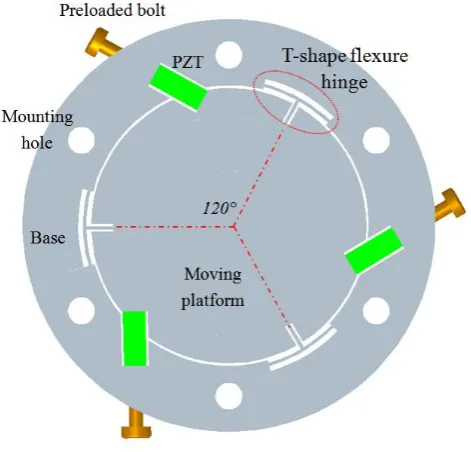
The solid model of the 3-DOF stage is shown in Fig. 1. The parallel driven
configuration is utilized in the design. It can be seen that the stage is mainly
composed of three piezoelectric actuators (PZTs), three T-shape flexure hinge
mechanisms, a moving platform and a base. Three T-shape flexure hinge mechanisms
are located at the same circle with the separation angle of 120°. Each T-shape flexure
hinge mechanism consists of three leaf-spring hinge (I, II and III) subsections
connected together like a T-joint as shown in Fig. 2. One end of each T-shape flexure
hinge mechanism is connected to the moving platform and the others are fixed on the
base. On the same circumference of the T-shape flexure hinge mechanism, there are
the T-shape flexure hinge mechanism with an angle of 60°. The PZT can be preloaded
through the behind fine screw bolt. By controlling the PZTs simultaneously, the
moving platform can implement the translations in the X and Y directions, and
[image:7.595.178.414.212.438.2]rotation about the Z axis.
Figure 1 3D solid model of the developed 3-DOF stage
Figure 2 Schematic diagram of the T-shape flexible hinge structure
The proposed 3-DOF stage was manufactured monolithically using wire
electrical discharge machining (WEDM) technology, and the material was selected as
I II
[image:7.595.242.365.489.658.2]Aluminum 7075-T6 with a Young’s modulus of 72 GPa, a yield strength in excess of
434 MPa. The top and bottom surfaces were machined using a milling machine to
guarantee the parallelism. Subsequently, artificial aging treatment method was utilized
to release the residual stress. Considering that the T-shape flexible hinge mechanism
must be inside the small and compact stage, the following parameters were
determined: the stage diameter is chosen as ϕ 150 mm, the thickness is set as 18 mm,
and the moving platform diameter is chosen as ϕ 100 mm. Therefore, three leaf-spring
hinges have the same hinge width of b=18 mm. The geometric parameters of the
[image:8.595.110.491.382.448.2]T-shape flexible hinge are listed in Table I.
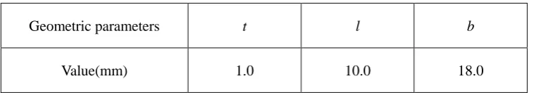
Table I: Geometric parameters of the T-shape flexible hinge.
Geometric parameters t l b
Value(mm) 1.0 10.0 18.0
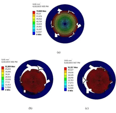
In order to examine the performance of the stage described above, modal
analysis is performed to examine the dynamic characteristics of the stage using finite
element analysis package ANSYS Workbench software. The material for the stage is
chosen as Aluminum 7075-T6 with a density of 2770 kg/m3, a Young's modulus of
71 GPa, and a Poisson's ratio of 0.33. In order to improve the computational accuracy,
the mapping mesh method is adopted. The mesh is strictly controlled in the areas of
flexure hinges, where the large deformation is generally occurred. The results are
shown in Fig. 3. When the piezoelectric actuators are not installed on the stage, the
first mode shape is the rotation about the Z-axis, and its frequency is 528.11Hz; the
respectively, with the corresponding frequencies of 626.92 Hz and 626.95 Hz. If the
PZTs are installed, it can be realized by incorporating spring-damper components into
the stage. It is considered as a spring with a constant stiffness k, and one end of the
spring is fixed and the other end is attached on the moving platform. The simulation
results show that the first three natural frequencies increase to 806.04 Hz, 801.13 Hz
and 931.20 Hz, and the corresponding mode shapes are the moving platform
translating in the Y-axis and X-axis, and rotating about the Z axis, respectively.
(a)
[image:9.595.100.491.319.697.2]
(b) (c)
Figure 3 First three mode shapes of the 3-DOF stage with no PZTs installed: (a) first mode shape
According to the above characteristics analysis, it validates that the stage can
provide both translational and rotational motions. In addition, the stage has a high
natural frequency, which ensures that the system has good dynamic characteristics.
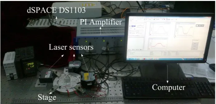
The prototype of the developed XYθz stage is shown in Fig. 4. The 3-DOF stage
is mounted on a Newport RS-4000 optical table to reduce the ground vibrations.
Three AE0505D18 PZTs were used with the maximum displacement of 15µm under
the input voltage of 100V. The dSPACE DS1103 controller was used to generate the
controlling signal, and the PI E-505.00 amplifier was used to amplify the signal to
drive the PZTs. Three KEYENCE laser displacement sensors LK-H050 were used to
[image:10.595.123.473.383.551.2]measure the motion of the stage.
Figure 4 Experimental setup of the stage
3. Dynamics modeling and system identification
3.1 Dynamics modeling
The model of the stage can be considered as mass and spring system, and it is
shown in Fig. 5. Based on the Newton’s second law of motion, the differential
equations for the dynamic motion of the flexure mechanism are given as Eq. (1). The
considered and all higher modes are neglected.
Figure 5 Dynamics model of the 3-DOF stage
BF A A M y x k y x c y x eqx eqx (1)
where: MDiag(meq meq Izz), ADiag(3 2 3 2 3r2)
r r r 2 1 2 1 1 2 3 2 3 0 B ,
Tpzt pzt
pzt f f
f 1 2 3
F , c pzt c pzt jx eqx k k k k k k
fpzt represents the driving force of the PZT, meq, ceq and Izz denote the equivalent mass,
the equivalent damping coefficient of the stage and moment of inertia about the
Z-axis, respectively, keqx is the X-axis linear stiffness of the stage, kjx is the X-axis
equivalent stiffness of the “T” type flexible hinge, kpzt is the stiffness of PZT, kc is the
equivalent Hertzian contact stiffness, r is the radius of the moving platform. B is
is equal to BBT, which represents the equivalent relationship between X, Y and θ.
To ensure that the PZTs and the moving platform are not separated during normal
operation, the PZTs are installed in slots and connected to the base by the bolt preload.
Therefore, the driving force of PZT can be obtained:
d k k k k f c pzt c pzt pzt
(2)
where d is the displacement output of the free PZT is given by:
pzt eV
d
d (3)
where de is a piezoelectric constant, Vpzt is the applied voltage. Thus:
3 3 2 2 1 1 1 2 2 2 0 0 0 0 0 0 0 0 0 0 0 0 2 pzt e pzt e pzt e c pzt c pzt n ny nx n ny y nx x V d V d V d k k k k y x w w w y x w w w y x B M (4)
where:w keqx meq w keqx meq w r keqx Izz
n ny nx 2 2 2 2 3 , 2 3 , 2
3
zz eq n eq eqx ny eq eqx
nx c m w c m w r c I
w 3 2 , 2 3 2 , 2 3 2
2 .
For dynamics modeling, it is usually defines the driving force as the input into
the system, which means that the PZT is considered to be a force generator with a
spring-damper mass units. However, the PZT has electric characteristics. In [37], Tian
proposed that the PZT could be electrically considered as a capacitance with an
equivalent circuit. Similar modeling approach has been used in [47-49].
Thus, in this paper, the piezoelectric actuator could be electrically considered as
a capacitance with an equivalent circuit as shown in Fig. 6, where Vpzt(t) is the actual
voltage applied to the piezoelectric actuator, Vd(t) is the input control signal, C, R is
the equivalent capacitance and resistance of PZT, respectively. Based on the
Figure 6 Equivalent driving circuit of the piezoelectric actuator ) ( ) ( ) ( t V t V dt t dV
RC pzt pzt d
.
(5)
When the initial input voltage is 0, based on Eq. (5) and it's Laplace transform, the
relationship between the input and output can be obtained:
V
sRCs s
Vpzt d
1 1
(6)
In this case, the signal from input voltage to the output of the displacement in (4) and
(6) can be described by a third-order system:
)) ( ) ( ) ( ( ) 1 )( 2 ( ] ) [( ) ( )) ( 2 1 ) ( 2 1 ) ( ( ) 1 )( 2 ( ] ) [( ) ( )) ( 2 3 ) ( 2 3 ( ) 1 )( 2 ( ] ) [( ) ( 3 2 1 2 2 3 2 1 2 2 3 2 2 2 s V s V s V RCs s s I k k k k r d s s V s V s V RCs s s m k k k k d s y s V s V RCs s s m k k k k d s x d d d n n zz c pzt c pzt e d d d ny ny x eq c pzt c pzt e d d nx nx x eq c pzt c pzt e (7)
Thus, the 3-DOF system can be described including both electrical and mechanical
characteristics.
3.2 System identification
From Eq. (7), it's known that the parameters for the dynamic model cannot be
obtained by simply using the theoretical calculations, because the exact information of
should be identified based on the input control voltage and the corresponding output
displacement.
In this study, a sweep signal is employed as the control input, which covers a
frequency range from 1 Hz to 3 kHz. In this case, the X and Y axes output
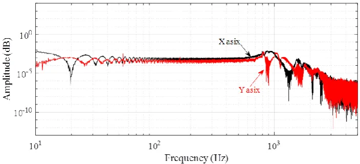
displacements are measured and recorded from 0 to 10 s. Fig. 7 shows the frequency
spectra of the stage’s responses in the X and Y axes, when only the PZT2 is activated.
Based on the frequency spectra, the first natural frequencies in the X and Y axes are
estimated to be 851.14 Hz and 812.83 Hz, respectively. Compared with the simulation
results, experiment results show that the natural frequencies of the stage are increased,
it means that the stage has better dynamic characteristics. This is benefited from the
installation of PZTs, which increase the stiffness in the actuation directions. In
[image:14.595.121.473.463.624.2]addition, it can be seen that the motion of the 3-DOF stage is coupled.
Figure 7 Frequency spectra of the stage’s response (only PZT2 is activated)
Based on the system modeled by Eq. (7), the identification is carried out with the
Matlab system identification toolbox. During the identification process, the
third-order systems are adopted to fit the measured data, and the identified results are
13 8 2 6 3 8 13 8 2 6 3 6 13 8 2 6 3 6 10 2661 . 3 10 1523 . 2 10 6032 . 5 10 4302 . 9 ) ( 10 11251 . 3 10 39141 . 5 10 00445 . 1 10 65372 . 2 ) ( 10 08642 . 3 10 30864 . 5 10 0005 . 1 10 16049 . 2 ) ( s s s s G s s s s G s s s s G y x (8)
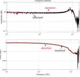
Fig. 8(a) shows the comparisons the X axis transfer function of the identified
model and experimental result. Similar result in the Y axis is obtained. The θ axis
transfer function of the identified model and experimental result also is described in
Fig. 8(b), and the natural frequencies in the θ axis are estimated to be 945.74 Hz. It
can be observed that the identified model can reasonably represent the physical
system in the frequency response. However, the deviation exists in the phase plot at
high frequencies. One of the reasons is the hysteresis effect, which always causes the
phaselag.
[image:15.595.130.428.75.210.2] [image:15.595.153.433.471.738.2](b)
Figure 8 (a) Frequency response of the transfer function in X axis, and (b) Frequency response of
the transfer function in θ axis
4. Experiments and discussions
[image:16.595.155.432.84.355.2]4.1 Decoupling control
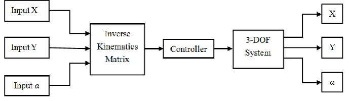
Figure 9 Decoupling control block diagram
As mentioned previously, the motion of the 3-DOF system is coupled. In order to
eliminate this coupling, the system is controlled in open-loop via inverse kinematics.
The control block diagram is presented in Fig. 9. Therefore, each axis output of the
system can be controlled independently when the system is controlled by the
[image:16.595.126.471.493.593.2]The motion stroke and coupled motion are tested, and the result is shown in Fig.
10. It can be seen that the maximum translational displacements in the X- and Y-
directions are 6.9 μm and 8.6μm, respectively, and rotational motion range is 289 μrad.
The decoupling characteristic is confirmed, the maximum coupled displacements in
the X- and Y- directions are 0.2346 μm and 0.2752 μm, respectively, and the
cross-axis coupling ratio is below 3.5% (3.4% in the X axis, 3.2% in the Y axis), it is
mainly due to the assembly errors, manufacture errors and the external disturbances.
In this case, the 3-DOF system, which is controlled in open-loop via inverse
kinematics can be treated as three Single-Input-Single-Output (SISO) systems.
(a) (b)
Figure 10 Experiment test of the motion stroke
4.2 Trajectory tracking
During operations, the control voltage is applied on the PZT, which is defined as
the input into the system. Due to the hysteresis and creep effects of the PZT, the
relationship between the input control voltage and the output displacement of the PZT
is nonlinear. In the literature, many hysteresis models have been developed to describe
the hysteresis nonlinearities such as Preisach model [38, 39], Maxwell model [40],
Duhem model [41], Bouc-Wen model [42-44], and Prandtl-Ishlinskii model [45]. In
this paper, the Bouc-Wen hysteresis model is selected as an illustration. Certainly,
other hysteresis models can also be selected. Without loss of generality, it has already
been verified that the Bouc-Wen model is suitable to describe the hysteresis loop of
PZT [46]. On the other hand, the model is considered in this work since it has fewer
parameters. The equation of a B-W model is shown as follows:
h V c h V b V ad
h epzt pzt pzt
(9)
where a, b and c are the parameters of this model, h is the hysteresis variable. And the
parameters identification is implemented by nonlinear least square toolbox running in
Matlab environment.
For the proposed 3-DOF stage, the hysteresis can be considered as B-W
hysteresis model. It describes the relationship between the input voltage and output
displacement. On the contrary, the input voltage used to produce a desired output
displacement is solved by its inverse hysteresis model, which will be applied to the
piezoelectric actuator. The block diagram of the control with hysteresis compensation
Figure 11 Block diagram of the 3-DOF system with hysteresis compensation
The inverse B-W model can be cascaded to the physical system as a feedforward
hysteresis compensator. In order to improve the stability of the tracking performance,
a feedback controller is necessary. Therefore, a proportional-integral controller is
employed to establish a feedforward-feedback hybrid controller. The schematic
diagram of the hybrid controller is proposed in Fig. 12.
Figure 12 The schematic diagram of the hybrid controller
To test the tracking capability of the 3-DOF system under the hybrid control
scheme, sinusoidal trajectory motion tests are conducted to evaluate the tracking
performance. Five sinusoidal trajectories with the same amplitude of 6 μm and
different frequencies of 0.1, 0.5, 1, 3 and 5 Hz, respectively, are utilized. Due to the
symmetry, only the tracking performance in the Y axis is presented. Fig. 13 shows the
experimental results on the five sinusoidal trajectories. For trajectories below 1 Hz, as
shown in Figs. 13(a), (b) and (c), the maximum tracking errors can be reduced to ±0.1
μm, which can be treated as external noise disturbances. However, for the fast
[image:19.595.109.486.334.448.2]±0.2036 and -0.3042 μm, which are as large as 3.393% and 5.07% with respect to the
[image:20.595.106.479.487.688.2]output displacement.
Fig. 14 shows two sinusoidal trajectories tracking on a rotation motion about the
Z axis with the same amplitude of 180 μrad and frequencies of 1 and 5 Hz,
respectively. The maximum tracking errors ±5.01 μrad and -15.21 μrad are observed
in the motion, which are as large as 2.783% and 8.45%, respectively, with respect to
the angular displacement.
Based on the above experimental results, we can find that with the increase of
the frequency of the input signal trajectory, the tracking capability of the stage is
severely decreasing. It means that the tracking errors increase with the increase of the
input frequencies. Thus, the method with fixed parameters is only applicable to
improve the tracking performance of the stage at low frequencies.
(c) (d)
[image:21.595.113.477.82.470.2](e)
Figure 13 The result of five different frequencies sinusoidal motion tracking: (a) 0.1 Hz, (b) 0.5 Hz, (c) 1 Hz, (d) 3 Hz and (e) 5 Hz
(a) (b)
[image:21.595.114.474.533.720.2](a) (b)
Figure 15 The result of two superimposed signal tracking: (a) smooth trajectory and (b) non-smooth trajectory
The stage’s tracking performance in the Y axis is also verified by tracking two
superimposed signal, a smooth trajectory defined by:
) 5 . 7 10 sin( ) 5 . 4 6 sin( ) 5 . 1 2 sin( 2 2 )
(t t t t
y (10)
Multiple triangular signals are superimposed and selected as other reference
trajectories. Period of the non-smooth signal is 2 seconds. The tracking results of the
above two trajectories are shown in Fig. 15. Different from the result in smooth
trajectories, the large tracking error for this non-smooth signal is found at the corners.
In order to examine the planar trajectory tracking performances of 3-DOF stage,
experimental results on the following trajectories are presented: (1) Two circular
trajectories of different frequencies centered at point (2.0 μm, 2.0 μm) with a radius of
2.0μm. (2) Two complex trajectories are chosen as the reference trajectories defined
by Eqs. (11) and (12), respectively.
(a) (b)
Figure 16 The result of two different frequencies circular trajectory tracking performance: (a) 0.1 Hz and (b) 0.5 Hz
(a) (b)
Figure 17 The result of two complex trajectories tracking performance
) 3 sin( ) 3 ( 3 ) (
) 15 . 0 3 sin( ) 3 ( 3 ) (
t t
t y
t t
t x
(12)
The experimental results are shown in Figs. 16 and 17. It provides the
discrepancies between the desired and actual trajectories. The tracking errors in the X
[image:23.595.114.479.374.577.2]From the experimental result, for the circular trajectories, it can be obviously
observed that the tracking error increases with the increase of the input frequencies.
This is similar to uniaxial motion tracking. As shown in Fig. 16(b), the maximum
tracking errors (0.0748 μm in X axis and 0.0596 μm in Y axis) with respect to the
output displacement are as large as 1.87% in the X axis and 1.49% in the Y axis,
respectively. However, for the complex trajectories, as shown in Fig. 17, compared
with the circular trajectories, it is found that the tracking performance is
unsatisfactory and obviously increased in tracking error. The maximum tracking error
(0.1536 μm in the X axis and 0.1069 μmin the Y axis) with respect to the output
displacement is as large as 2.56% in the X axis and 1.78% in the Y axis, respectively.
The results of the cross-axis coupling displacement are also obtained in the
hybrid controller experiment. The coupled displacements in the X- and Y- directions
are 0.175 μm and 0.151 μm, respectively. The cross-axis coupling ratio is 2.91% in
the X axis and 2.52% in the Y axis, respectively. This indicates that the proposed
closed-loop control methodology can reduce the cross-axis coupling motion and
further improve the positioning accuracy.
It is difficult to reduce the tracking error of the 3-DOF system for double axes
trajectories. This is because the cross-axis couplings errors. Therefore, the future work
is committed to developing suitable controllers that are capable of improving the
5. Conclusion
A XYθz stage has been developed, and the dynamic modeling, system
identification and experimental evaluation for the motion control of the stage have
been explored. The obtained conclusions of this paper are summarized as follows:
1) A XYθz stage is designed, and it is driven by three PZTs and guided by three
special T-shape hinges. Each T-shape hinge consists of three leaf-spring hinge
subsections connected together like a T-joint.
2) Considering both of the electrical and mechanical characteristics, the dynamic
model of the 3-DOF stage can be established as a third-order dynamic system to
investigate the relationship between the input voltage and the output displacement.
The system identification toolbox is utilized to estimate the parameters of the
third-order dynamic model.
3) Experimental tests of the prototype stage with the decoupling control are
conducted to verify the effectiveness of decoupling control law. The proposed stage
has the translation motion strokes of 6.9 and 8.6 µm in the X- and Y-axes, respectively,
and rotational range of 289 µrad about the Z-axis. The different motion trajectories
are also performed to verify the tracking capability of the stage, which validates good
Acknowledgement
This research is supported by National Natural Science Foundation of China (Nos.
51275337, 51205279, 51675371, 51420105007), Reserved Academic Program of
Peiyang Scholar, and China Scholarship Council.
References
[1] T. Ando. High-speed AFM imaging. Current Opinion in Structural Biology 2014; 28: 63-68.
[2] S. S. Park, M. G. Mostofa, C. I. Park, M. Mehrpouya, S. Kim. Vibration assisted nano
mechanical machining using AFM probe. CIRP Annals-Manufacturing Technology 2014; 63
(1): 537-540.
[3] F. Wang, J. Li, S. Liu, X. Zhao, D. Zhang, Y. Tian. An improved adaptive genetic algorithm for
image segmentation and vision alignment used in microelectronic bonding, IEEE/ASME
Transactions on Mechatronics 2014; 19(3): 916-923.
[4] P. Gao, S. Swei. A six-degree-of-freedom micro-manipulator based on piezoelectric translators,
Nanotechnology 1999; 10(4): 447-452.
[5] Y. Tian, B. Shirinzadeh, D. Zhang. Design and dynamics of a 3-DOF flexure-based parallel
mechanism for micro/nano manipulation. Microelectronic Engineering 2010; 87(2): 230-241.
[6] J. Paros, L. Weisbord. How to design flexure hinges. Machine Design 1965; (November):
151-156.
[7] Y. Tian, B. Shirinzadeh, D. Zhang. A flexure-based mechanism and control metrology for
ultra-precision turning operation. Precision Engineering 2009; 33(2): 160-166.
[8] T. Tomas, H. Walter, R. Hugo, L. John, P. Angeliki and S. Abu. Dual-stage nanopositioning for
high-speed scanning probe microscopy. IEEE/ASME TRANSACTIONS ON
MECHATRONICS 2014; 19(3): 1035-1045.
[9] F. Makoto, H. Masato, M. Sintaro. Generating sub-nanometer displacement using reduction
mechanism consisting of torsional leaf spring hinges. MEASUREMENT SCIENCE
REVIEW 2014; 14(1): 48-51.
[10] Q. Xu. A novel compliant micropositioning stage with dual ranges and resolutions. Sensors
[11] Q. Xu. Design and development of a compact flexure-based XY precision positioning system
with centimeter range. IEEE TRANSACTIONS ON INDUSTRIAL ELECTRONICS 2014;
61(2): 893-903.
[12] S. Smith, V. Badami, J. Dale, Y. Xu. Elliptical flexure hinges. Review of Scientific
Instruments 2000; 68(3): 1474-1483.
[13] Y. Tian, B. Shirinzadeh, D. Zhang. Closed-form compliance equations of filleted V-shaped
flexure hinges for compliant mechanism design. Precision Engineering 2010; 34(3): 408-418.
[14] L.L. Howell. Compliant Mechanisms, Wiley, New York, 2001.
[15] B. Trease, Y. Moon, S. Kota.Design of large-displacement compliant joints. ASME Journal of
Mechanical Design 2005; 127(4): 788-798.
[16] B.D. Jensen, L.L. Howell. The modeling of cross-axis flexural pivots. Mechanism and
Machine Theory 2002; 37(5): 461-476.
[17] M. Goldfarb, J. Speich. The development of a split-tube flexure. The ASME Dynamics and
Control Div 2000; 2: 861-866.
[18] S.T. Smith. Flexures: Elements of Elastic Mechanisms, Gordon and Breach Science, New
York, 2000.
[19] S. Venanzi, P. Giesen, V. Parenti-Castelli. A novel technique for position analysis of planar
compliant mechanisms. Mechanism and Machine Theory 2005; 40(11): 1224-1239.
[20] W.O. Schotborgh, F.G. Kokkeler, H. Tragter. Dimensionless design graphs for flexure
elements and a comparison between three flexure elements. Precision Engineering 2005;
29(1): 41-47.
[21] X. Pei, J. Yu, G. Zong, S. Bi, H. Su. The modeling of cartwheel flexural hinges. Mechanism
and Machine Theory 2009; 44(10): 1900-1909.
[22] D. Kang, D. Gweon. Analysis and design of a cartwheel-type flexure hinge. Precision
Engineering 2013; 37(1): 33-43.
[23] Y. Tian, B. Shirinzadeh, D. Zhang. A flexure-based five-bar mechanism for micro/nano
manipulation. Sensors and Actuators A: Physical 2009; 153(1): 96-104.
[24] Y. Tian, B. Shirinzadeh, D. Zhang, X. Liu, D. Chetwynd. Design and forward kinematics of
the compliant micro-manipulator with lever mechanisms. Precision Engineering 2009; 33(4):
466-475.
[25] Y. Tian, C. Liu, X. Liu, F. Wang, X. Li, Y. Qin, D. Zhang, B. Shirinzadeh, Design, modeling
and characterization of a 2-DOF precision positioning platform, Transactions of the Institute
of Measurement and Control (2014), doi: 10.1177/0142331214540692.
Optimization of a Decoupled 2-DOF Monolithic Mechanism. IEEE/ASME Transactions on
Mechatronics 2014; 19(3): 872-881.
[27] Y. QIN, Y. TIAN, and D. ZHANG. Design and Dynamic Modeling of a 2-DOF Decoupled
Flexure-Based Mechanism. CHINESE JOURNAL OF MECHANICAL ENGINEERING
2012; 25(4): 688-696.
[28] F. Wang, Z. Ma, W. Gao, X. Zhao, Y. Tian, D. Zhang, C. Liang. Dynamic modelling and
control of a novel XY positioning stage for semiconductor packaging, Transactions of the
Institute of Measurement and Control 2015; 37 (2): 177-189.
[29] F. Wang, X. Zhao, D. Zhang, et al. Robust and precision control for a directly-driven XY
table. Proceedings of the Institution of Mechanical Engineers, Part C: Journal of Mechanical
Engineering Science 2011; 225(5): 1107-1120.
[30] F. Wang, X. Zhao, D. Zhang, et al. Design and control of a high-acceleration precision
positioning system using a novel flexible decoupling mechanism. Proceedings of the
Institution of Mechanical Engineers, Part C: Journal of Mechanical Engineering Science
2010; 224(2): 431-442.
[31] S. Polit, J. Dong. Development of a high-bandwidth XY nanopositioning stage for high-rate
micro/nano manufacturing, IEEE/ASME Transactions on Mechatronics 2011; 16(4);
724-733.
[32] Y. Qin, B. Shirinzadeh, D. Zhang, Y. Tian. Design and kinematics modeling of a novel 3-DOF
monolithic manipulator featuring improved Scott-Russell mechanisms. Journal of
Mechanical Design 2013; 135(10): 101004-1-101004-9.
[33] Z. Guo, Y. Tian, C. Liu, F. Wang, X. Liu, B. Shirinzadeh, D. Zhang. Design and control
methodology of a 3-DOF flexure-based mechanism for micro/nano positioning, Robotics and
Computer Integrated Manufacturing 2015; 32: 93-105.
[34] H. Kim and D. Gweon. Development of a compact and long range XYθz nano-positioning
stage. REVIEW OF SCIENTIFIC INSTRUMENTS 2012; 83(8): 085102-1-085102-8.
[35] U. Bhagat, B. Shirinzadeh, L. Clark, P. Chea, Y. Qin, Y. Tian, D. Zhang. Design and analysis
of a novel flexure-based 3-DOF mechanism. Mechanism and Machine Theory 2014; 74:
173-187.
[36] H. Kim, D. Ahn, and D. Gweon. Development of a novel 3-degrees of freedom flexure based
positioning system. REVIEW OF SCIENTIFIC INSTRUMENTS 2012; 83(5):
055114-1-055114-11.
[37] Y. Tian, D. Zhang, B. Shirinzadeh, Dynamic modelling of a flexure-based mechanism for
[38] Y. Ting, H.-C.Jar and C.-C. Li, Measurement and calibration for Stewart micromanipulation
system, Precision Engineering 2007; 31(3): 226-233
[39] Boukari A-F, Carmona J-C, Moraru G, Malburet F, Chaaba A, Douimi M. Piezoactuators
modeling for smart applications. Mechatronics 2011; 21(1): 339-349.
[40] Juhasz L, Maas J, Borovac B. Parameter identification and hysteresis compensation of
embedded piezoelectric stack actuators. Mechatronics 2011; 21(1): 329-338.
[41] C. Lin, P. Lin. Tracking control of a biaxial piezo-actuated positioning stage using
generalized Duhem model. Computers and Mathematics with Applications 2012; 64(5):
766-787.
[42] M. Rakotondrabe. Bouc-Wen modeling and inverse multiplicative structure to compensate
hysteresis nonlinearity in piezoelectric actuators. IEEE Transactions on Automation and
Engineering 2011; 8(2): 428-431.
[43] Y.-T. Liu, K.-M. Chang and W.-Z. Li. Model reference adaptive control for a
piezo-positioning system. Precision Engineering 2010; 34(1): 62-69.
[44] J. Park and W. Moon. Hysteresis compensation of piezoelectric actuators: The modified
Rayleigh model. Ultrasonics 2010; 50(3): 335-339.
[45] X. Y. Zhang and Y. Lin. Adaptive tracking control for a class of pure-feedback non-linear
systems including actuator hysteresis and dynamic uncertainties. IET Control Theory and
Applications 2011; 5(16): 1868-1880.
[46] T. S. Low and W. Guo. Modeling of a three-layer piezoelectric bimorph beam with hysteresis.
J. MEMS 1995; 4(4): 230-237.
[47] M. Goldfarb and N. Celanovic. Modeling piezoelectric stack actuators for control of
micromanipulation. IEEE Control Syst. Mag. 1997; 17(3): 69-79.
[48] H. J. M. T. A. Adriaens, W. L. D. Koning, and R. Banning. Modeling piezoelectric actuators.
IEEE/ASME Trans. Mechatronics 2000; 5(4): 331-341.
[49] Y. S. Gao, D. W. Zhang, and C. W. Yu. Dynamic modeling of a novel workpiece table for